2006 SUZUKI SX4 cable
[x] Cancel search: cablePage 279 of 1556
Downloaded from www.Manualslib.com manuals search engine Engine Electrical Devices: 1C-11
Crankshaft Position (CKP) Sensor InspectionS6RW0D1306015
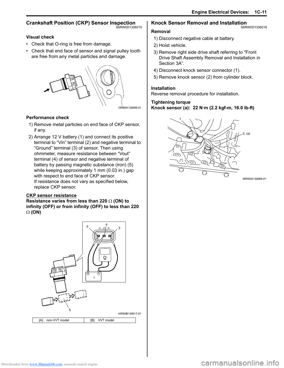
Visual check
• Check that O-ring is free from damage.
• Check that end face of sensor and signal pulley tooth
are free from any metal particles and damage.
Performance check
1) Remove metal particles on end face of CKP sensor,
if any.
2) Arrange 12 V battery (1) and connect its positive
terminal to “Vin” terminal (2) and negative terminal to
“Ground” terminal (3) of sensor. Then using
ohmmeter, measure resistance between “Vout”
terminal (4) of sensor and negative terminal of
battery by passing magnetic substance (iron) (5)
while keeping approximately 1 mm (0.03 in.) gap
with respect to end face of CKP sensor.
If resistance does not vary as specified below,
replace CKP sensor.
CKP sensor resistance
Resistance varies from less than 220 Ω (ON) to
infinity (OFF) or from infinity (OFF) to less than 220
Ω (ON)
Knock Sensor Removal and InstallationS6RW0D1306016
Removal
1) Disconnect negative cable at battery.
2) Hoist vehicle.
3) Remove right side drive shaft referring to “Front
Drive Shaft Assembly Removal and Installation in
Section 3A”.
4) Disconnect knock sensor connector (1).
5) Remove knock sensor (2) from cylinder block.
Installation
Reverse removal procedure for installation.
Tightening torque
Knock sensor (a): 22 N·m (2.2 kgf-m, 16.0 lb-ft)
[A]: non-VVT model [B]: VVT model
I3RB0A130006-01
I4RS0B130017-01
1
2, (a)
I5RW0A130009-01
Page 280 of 1556
Downloaded from www.Manualslib.com manuals search engine 1C-12 Engine Electrical Devices:
Main Relay, Fuel Pump Relay, Starting Motor
Control Relay, Throttle Actuator Control Relay
and Radiator Cooling Fan Relay Inspection
S6RW0D1306017
1) Disconnect negative cable at battery.
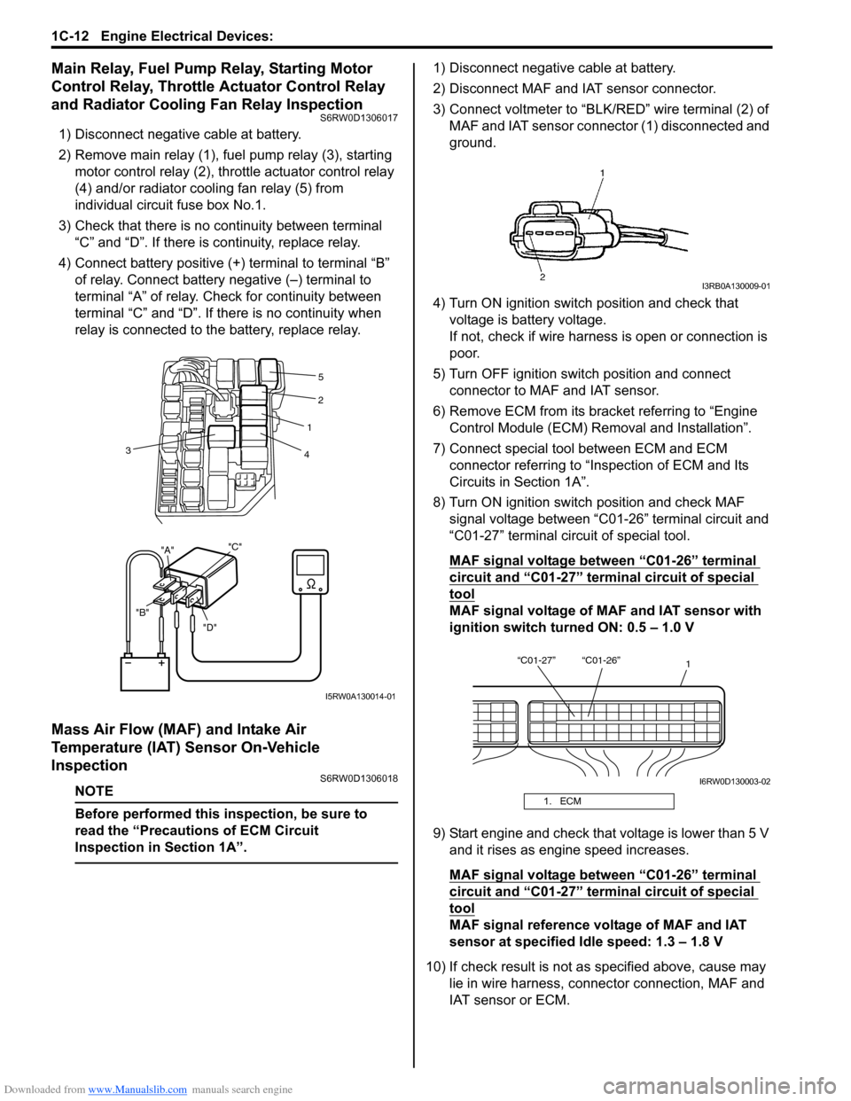
2) Remove main relay (1), fuel pump relay (3), starting
motor control relay (2), throttle actuator control relay
(4) and/or radiator cooling fan relay (5) from
individual circuit fuse box No.1.
3) Check that there is no continuity between terminal
“C” and “D”. If there is continuity, replace relay.
4) Connect battery positive (+) terminal to terminal “B”
of relay. Connect battery negative (–) terminal to
terminal “A” of relay. Check for continuity between
terminal “C” and “D”. If there is no continuity when
relay is connected to the battery, replace relay.
Mass Air Flow (MAF) and Intake Air
Temperature (IAT) Sensor On-Vehicle
Inspection
S6RW0D1306018
NOTE
Before performed this inspection, be sure to
read the “Precautions of ECM Circuit
Inspection in Section 1A”.
1) Disconnect negative cable at battery.
2) Disconnect MAF and IAT sensor connector.
3) Connect voltmeter to “BLK/RED” wire terminal (2) of
MAF and IAT sensor connector (1) disconnected and
ground.
4) Turn ON ignition switch position and check that
voltage is battery voltage.
If not, check if wire harness is open or connection is
poor.
5) Turn OFF ignition switch position and connect
connector to MAF and IAT sensor.
6) Remove ECM from its bracket referring to “Engine
Control Module (ECM) Removal and Installation”.
7) Connect special tool between ECM and ECM
connector referring to “Inspection of ECM and Its
Circuits in Section 1A”.
8) Turn ON ignition switch position and check MAF
signal voltage between “C01-26” terminal circuit and
“C01-27” terminal circuit of special tool.
MAF signal voltage between “C01-26” terminal
circuit and “C01-27” terminal circuit of special
tool
MAF signal voltage of MAF and IAT sensor with
ignition switch turned ON: 0.5 – 1.0 V
9) Start engine and check that voltage is lower than 5 V
and it rises as engine speed increases.
MAF signal voltage between “C01-26” terminal
circuit and “C01-27” terminal circuit of special
tool
MAF signal reference voltage of MAF and IAT
sensor at specified Idle speed: 1.3 – 1.8 V
10) If check result is not as specified above, cause may
lie in wire harness, connector connection, MAF and
IAT sensor or ECM.
"D" "B""A""C"
2
1
4 3
5
I5RW0A130014-01
1. ECM
I3RB0A130009-01
“C01-27” “C01-26”
1
I6RW0D130003-02
Page 281 of 1556
Downloaded from www.Manualslib.com manuals search engine Engine Electrical Devices: 1C-13
Mass Air Flow (MAF) and Intake Air
Temperature (IAT) Sensor Removal and
Installation
S6RW0D1306019
CAUTION!
• Do not disassemble MAF and IAT sensor.
• Do not expose MAF and IAT sensor to any
shock.
• Do not clean MAF and IAT sensor.
• If MAF and IAT sensor has been dropped, it
should be replaced.
• Do not blow compressed air by using air
gun or the like.
• Do not put finger or any other object into
MAF and IAT sensor. Malfunction may
occur.
Removal
1) Disconnect negative cable at battery.
2) Disconnect MAF and IAT sensor connector.
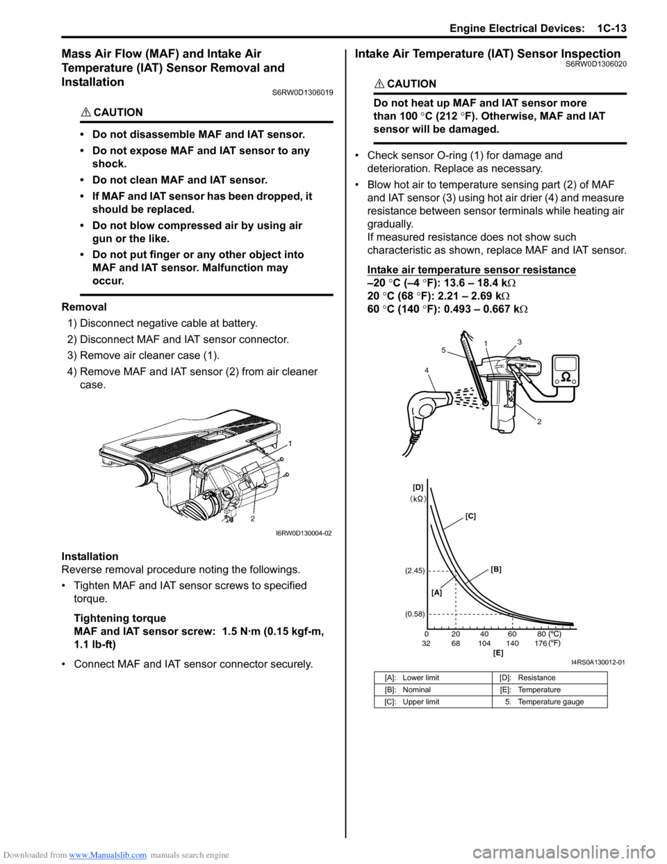
3) Remove air cleaner case (1).
4) Remove MAF and IAT sensor (2) from air cleaner
case.
Installation
Reverse removal procedure noting the followings.
• Tighten MAF and IAT sensor screws to specified
torque.
Tightening torque
MAF and IAT sensor screw: 1.5 N·m (0.15 kgf-m,
1.1 lb-ft)
• Connect MAF and IAT sensor connector securely.
Intake Air Temperature (IAT) Sensor InspectionS6RW0D1306020
CAUTION!
Do not heat up MAF and IAT sensor more
than 100 °C (212 °F). Otherwise, MAF and IAT
sensor will be damaged.
• Check sensor O-ring (1) for damage and
deterioration. Replace as necessary.
• Blow hot air to temperature sensing part (2) of MAF
and IAT sensor (3) using hot air drier (4) and measure
resistance between sensor terminals while heating air
gradually.
If measured resistance does not show such
characteristic as shown, replace MAF and IAT sensor.
Intake air temperature sensor resistance
–20 °C (–4 °F): 13.6 – 18.4 kΩ
20 °C (68 °F): 2.21 – 2.69 kΩ
60 °C (140 °F): 0.493 – 0.667 kΩ
I6RW0D130004-02
[A]: Lower limit [D]: Resistance
[B]: Nominal [E]: Temperature
[C]: Upper limit 5. Temperature gauge
20 0
68 32 104 140 17640 60 80 (2.45)
(0.58)
1
2 3
45
[A][B]
[E] [C] [D]
I4RS0A130012-01
Page 289 of 1556

Downloaded from www.Manualslib.com manuals search engine Engine Mechanical: 1D-7
7) Install air cleaner assembly with air suction hose
referring to “Air Cleaner Assembly Removal and
Installation”.
8) Run engine at specified idle speed and read vacuum
gauge. Vacuum should be within specification.
Vacuum specification (at sea level)
59 – 73 kPa (45 – 55 cmHg, 17.7 – 21.6 in.Hg) at
specified idle speed
9) After checking, disconnect special tool (Vacuum
gauge) from PCV valve.
10) Detach blind cap from PCV valve.
11) Install air cleaner assembly with air suction hose
referring to “Air Cleaner Assembly Removal and
Installation”.
Valve Lash (Clearance) InspectionS6RW0D1404003
1) Remove negative cable at battery.
2) Remove cylinder head cover referring to “Cylinder
Head Cover Removal and Installation”.
3) Remove right side engine under cover, if necessary.
4) Using 17 mm wrench, turn crankshaft pulley (1)
clockwise until cam lobes (2) become perpendicular
to shim faces (3) at valves “1” and “7” as shown in
figure.
5) Check valve lashes with thickness gauge (4)
according to the following procedure.
a) Check valve lashes at valves “1” and “7”.
b) Turn camshafts by 90° (by turning crankshaft
with wrench).
c) Make sure that cam lobes are perpendicular to
shim faces at valves to be checked (in this case,
“3” and “8”), if not, adjust it by turning crankshaft.
Check valve lashes.
d) In the same manner as b) – c), check valve
lashes at valves “4” and “6”.
e) In the same manner as b) – c) again, check
valve lashes at valves “2” and “5”.
If valve lash is out of specification, record valve lash and
adjust it to specification by replacing shim.
Valve clearance specification
When cold (Coolant temperature is 15 – 25 °C (59 –
77 °F)):
• Intake: 0.18 – 0.22 mm (0.007 – 0.009 in.)
• Exhaust: 0.28 – 0.32 mm (0.011 – 0.013 in.)
When hot (Coolant temperature is 60 – 68 °C (140 –
154 °F)):
• Intake: 0.21 – 0.27 mm (0.008 – 0.011 in.)
• Exhaust: 0.30 – 0.36 mm (0.012 – 0.014 in.)Replacement of Shim
1) Close the valve whose shim (2) is to be replaced by
turning crankshaft, then turn tappet (3) till its cut
section (1) faces inside as shown in figure.
I3RM0A140004-01
I2RH0B140006-01
Page 293 of 1556
Downloaded from www.Manualslib.com manuals search engine Engine Mechanical: 1D-11
Air Cleaner Assembly Removal and InstallationS6RW0D1406046
Removal
1) Disconnect negative cable at battery.
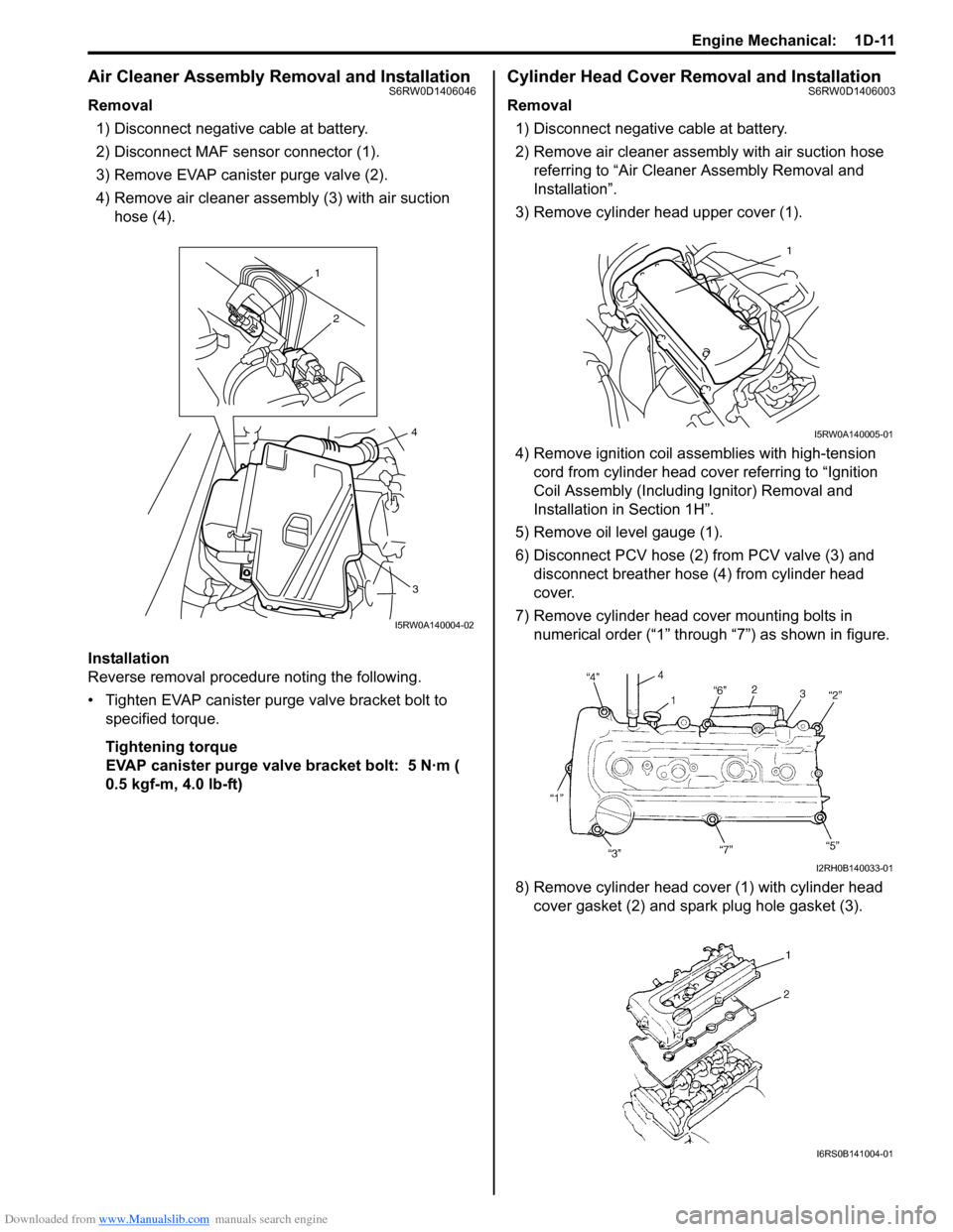
2) Disconnect MAF sensor connector (1).
3) Remove EVAP canister purge valve (2).
4) Remove air cleaner assembly (3) with air suction
hose (4).
Installation
Reverse removal procedure noting the following.
• Tighten EVAP canister purge valve bracket bolt to
specified torque.
Tightening torque
EVAP canister purge valve bracket bolt: 5 N·m (
0.5 kgf-m, 4.0 lb-ft)
Cylinder Head Cover Removal and InstallationS6RW0D1406003
Removal
1) Disconnect negative cable at battery.
2) Remove air cleaner assembly with air suction hose
referring to “Air Cleaner Assembly Removal and
Installation”.
3) Remove cylinder head upper cover (1).
4) Remove ignition coil assemblies with high-tension
cord from cylinder head cover referring to “Ignition
Coil Assembly (Including Ignitor) Removal and
Installation in Section 1H”.
5) Remove oil level gauge (1).
6) Disconnect PCV hose (2) from PCV valve (3) and
disconnect breather hose (4) from cylinder head
cover.
7) Remove cylinder head cover mounting bolts in
numerical order (“1” through “7”) as shown in figure.
8) Remove cylinder head cover (1) with cylinder head
cover gasket (2) and spark plug hole gasket (3).
1
2
3
4
I5RW0A140004-02
1
I5RW0A140005-01
I2RH0B140033-01
I6RS0B141004-01
Page 294 of 1556

Downloaded from www.Manualslib.com manuals search engine 1D-12 Engine Mechanical:
Installation
1) Install new spark plug hole gaskets (1) and new
cylinder head cover gasket (2) to cylinder head cover
(3) as shown in figure.
2) Remove oil, old sealant, and dust from sealing
surfaces on cylinder head and cover. After cleaning,
apply sealant “A” to the following point.
• Cylinder head cover gasket (1) sealing surface
area (2) as shown.
“A”: Water tight sealant 99000–31250
(SUZUKI Bond No.1207F)• Timing chain cover (1) and cylinder head (2)
mating surface as shown.
“A”: Water tight sealant 99000–31250
(SUZUKI Bond No.1207F)
3) Install cylinder head cover to cylinder head.
NOTE
When installing cylinder head cover, use care
so that cylinder head cover gasket or spark
plug hole gaskets will not get out of place or
fall off.
4) Tightening bolts in numerical order (“1” through “7”)
as shown in figure a little at a time till they are
tightened to specified torque.
Tightening torque
Cylinder head cover bolt (a): Tighten 8 N⋅m (0.8
kgf-m, 6.0 lb-ft) by the specified procedure
5) Connect PCV hose (2) to PCV valve (3).
6) Connect breather hose (4).
7) Install oil level gauge (1).
8) Install ignition coil assemblies to cylinder head cover
referring to “Ignition Coil Assembly (Including Ignitor)
Removal and Installation in Section 1H”.
9) Connect ignition coil couplers and clamp harness
securely.
10) Install cylinder head upper cover.
11) Install air cleaner assembly referring to “Air Cleaner
Assembly Removal and Installation”.
12) Connect negative cable at battery.I6RS0B141005-01
I2RH0B140036-01
I2RH0B140037-01
I3RH0B140016-01
Page 296 of 1556
Downloaded from www.Manualslib.com manuals search engine 1D-14 Engine Mechanical:
Throttle Body On-Vehicle InspectionS6RW0D1406006
Check electric throttle body assembly referring to
“Throttle Valve Operation Check” and “Electric Throttle
Body Assembly Operation Check” under “Electric
Throttle Body Assembly On-Vehicle Inspection in
Section 1C”.
Electric Throttle Body Assembly Removal and
Installation
S6RW0D1406047
CAUTION!
Never disassemble electric throttle body.
Disassembly will spoil its original
performance. If faulty condition is found,
replace it with new one.
Removal
1) Disconnect negative cable at battery.
2) Drain coolant referring to “Cooling System Draining
in Section 1F”.
3) Remove air cleaner assembly referring to “Air
Cleaner Assembly Removal and Installation”.
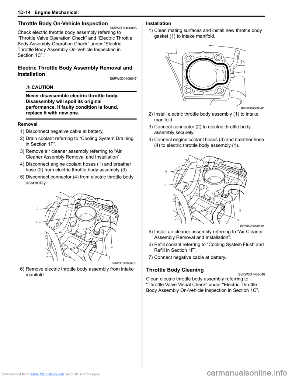
4) Disconnect engine coolant hoses (1) and breather
hose (2) from electric throttle body assembly (3).
5) Disconnect connector (4) from electric throttle body
assembly.
6) Remove electric throttle body assembly from intake
manifold.Installation
1) Clean mating surfaces and install new throttle body
gasket (1) to intake manifold.
2) Install electric throttle body assembly (1) to intake
manifold.
3) Connect connector (2) to electric throttle body
assembly securely.
4) Connect engine coolant hoses (3) and breather hose
(4) to electric throttle body assembly (1).
5) Install air cleaner assembly referring to “Air Cleaner
Assembly Removal and Installation”.
6) Refill coolant referring to “Cooling System Flush and
Refill in Section 1F”.
7) Connect negative cable at battery.
Throttle Body CleaningS6RW0D1406048
Clean electric throttle body assembly referring to
“Throttle Valve Visual Check” under “Electric Throttle
Body Assembly On-Vehicle Inspection in Section 1C”.
2
4
3
1
I5RW0C140006-01
1
I4RS0B140005-01
4
2
1
3
I5RW0C140008-01
Page 299 of 1556

Downloaded from www.Manualslib.com manuals search engine Engine Mechanical: 1D-17
Engine Assembly Removal and InstallationS6RW0D1406013
Removal
1) Relieve fuel pressure according to “Fuel Pressure
Relief Procedure in Section 1G”.
2) Disconnect negative and positive cable at battery.
3) Disconnect ECM connectors.
4) Remove battery and battery tray with ECM.
5) Remove right and left side engine under covers.
6) Remove A/C compressor belt by referring to
“Compressor Drive Belt Removal and Installation in
Section 7B” or “Compressor Drive Belt Removal and
Installation in Section 7B”.
7) Drain engine oil referring to “Engine Oil and Filter
Change in Section 0B”.
8) Drain transaxle oil referring to “Manual Transaxle Oil
Change in Section 5B” or “A/T Fluid Change in
Section 5A”.
9) Drain transfer oil referring to “Transfer Oil Change in
Section 3C”.
10) Drain coolant referring to “Cooling System Draining
in Section 1F”
11) Remove air cleaner assembly referring to “Air
Cleaner Assembly Removal and Installation”.
12) With hose connected, detach A/C compressor from
its bracket referring to “Compressor Assembly
Removal and Installation in Section 7B” or
“Compressor Assembly Removal and Installation in
Section 7B”.
CAUTION!
Suspend removed A/C compressor at a place
where no damage will be caused during
removal and installation of engine assembly.
13) Remove cylinder upper cover (1).14) Disconnect the following electric wires/connectors
and each clamps.
• TP sensor (1)
• MAP sensor (2)
• ECT sensor (3)
•EGR valve (4)
• CMP sensor (5)
• Ignition coil assembly (6)
• Injector (7)
•HO2S (8)
• Oil control valve (9) (for engine with VVT system)
• Engine oil pressure switch (10)
• CKP sensor (12)
• Knock sensor (13)
• Generator (14)
• Starting motor (15)
• Ground terminal (16) from cylinder block
• Battery ground cable (17) from transaxle
• Back-up light switch (18) (for M/T model)
• Torque sensor (19)
• P/S motor (20)
• Output shaft speed sensor (VSS) (29) (for A/T
model)
• Solenoid valve (30) (for A/T model)
• Transmission range sensor (31) (for A/T model)
• Input shaft speed sensor (32) (for A/T model)
15) Disconnect the following cables, and remove control
cable bracket (23)
• Gear select control cable (21) (for M/T model)
• Gear shift control cable (22) (for M/T model)
• A/T select cable (33) (for A/T model)
16) Disconnect the following hoses.
• Brake booster hose (24) from intake manifold
• Radiator inlet and outlet hoses (25) from radiator
• Heater inlet and outlet hoses (26) from heater
core
• Fuel feed hose (27) from fuel feed pipe
• Fuel vapor hose (11) from fuel vapor pipe
• Clutch hose (28) from transaxle (for M/T model)
• A/T fluid cooler hoses (for A/T model)
F: Vehicle forward 8. Engine front mounting bracket : 55 N⋅m (5.5 kgf-m, 40.0 lb-ft)
1. Engine right mounting bracket 9. Engine front mounting
: Be sure to direct yellow mark to forward.: 95 N⋅m (9.5 kgf-m, 69.0 lb-ft)
2. Engine right mounting 10. Transfer : 65 N⋅m (6.5 kgf-m, 47.0 lb-ft)
3. Engine left mounting bracket 11. Suspension frame : 25 N⋅m (2.5 kgf-m, 18.0 lb-ft)
1
I5RW0A140009-01