2006 SUZUKI SX4 height
[x] Cancel search: heightPage 1323 of 1556
Downloaded from www.Manualslib.com manuals search engine Lighting Systems: 9B-4
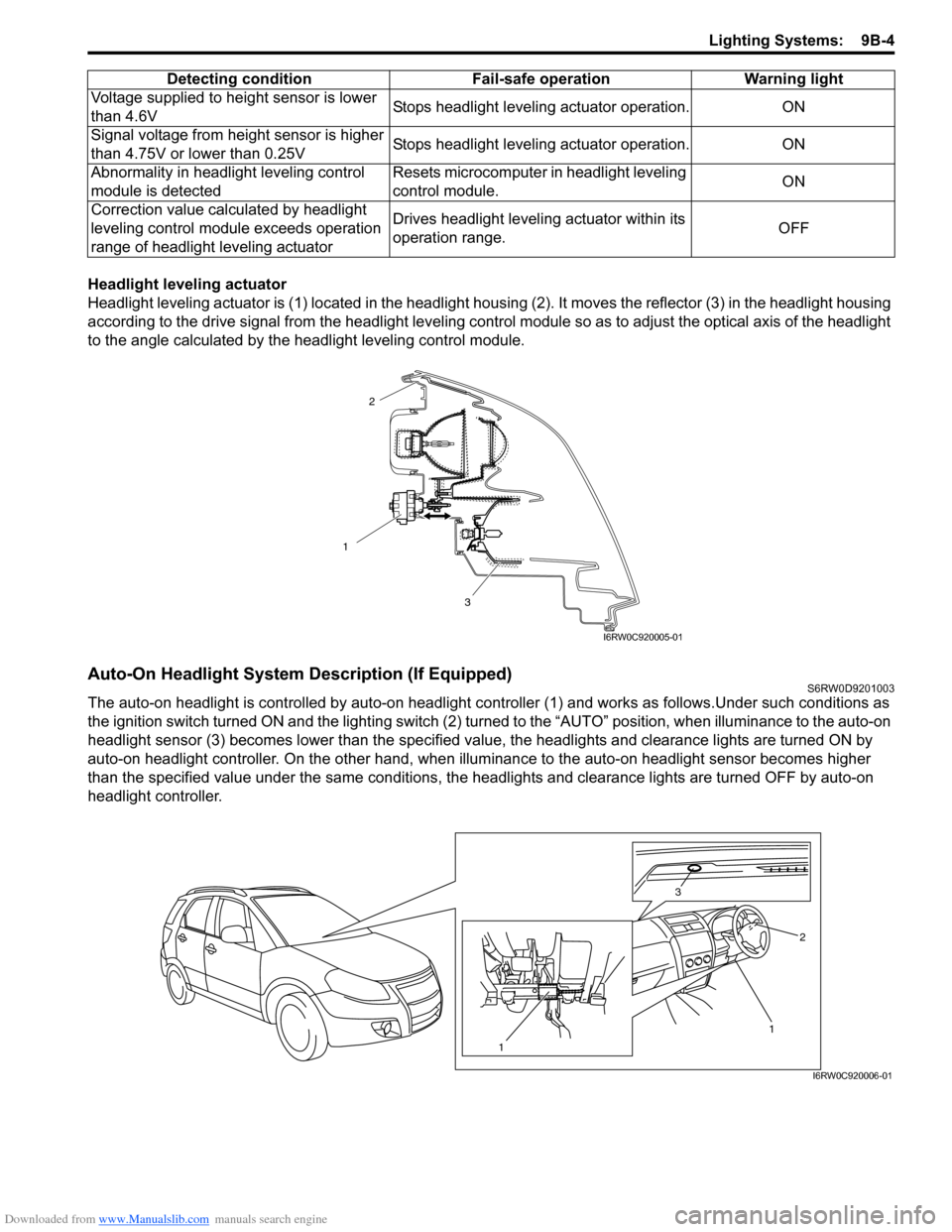
Headlight leveling actuator
Headlight leveling actuator is (1) located in the headlight housing (2). It moves the reflector (3) in the headlight housing
according to the drive signal from the headlight leveling control module so as to adjust the optical axis of the headlight
to the angle calculated by the headlight leveling control module.
Auto-On Headlight System Description (If Equipped)S6RW0D9201003
The auto-on headlight is controlled by auto-on headlight controller (1) and works as follows.Under such conditions as
the ignition switch turned ON and the lighting switch (2) turned to the “AUTO” position, when illuminance to the auto-on
headlight sensor (3) becomes lower than the specified value, the headlights and clearance lights are turned ON by
auto-on headlight controller. On the other hand, when illuminance to the auto-on headlight sensor becomes higher
than the specified value under the same conditions, the headlights and clearance lights are turned OFF by auto-on
headlight controller.Voltage supplied to height sensor is lower
than 4.6VStops headlight leveling actuator operation. ON
Signal voltage from height sensor is higher
than 4.75V or lower than 0.25VStops headlight leveling actuator operation. ON
Abnormality in headlight leveling control
module is detectedResets microcomputer in headlight leveling
control module.ON
Correction value calculated by headlight
leveling control module exceeds operation
range of headlight leveling actuatorDrives headlight leveling actuator within its
operation range.OFF Detecting condition Fail-safe operation Warning light
1
3
2
I6RW0C920005-01
1 3
2
1
I6RW0C920006-01
Page 1324 of 1556
Downloaded from www.Manualslib.com manuals search engine 9B-5 Lighting Systems:
Schematic and Routing Diagram
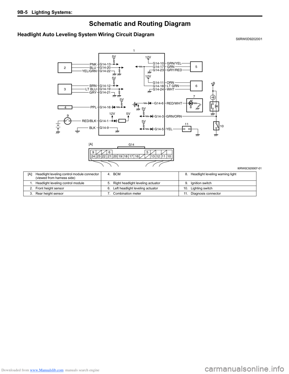
Headlight Auto Leveling System Wiring Circuit DiagramS6RW0D9202001
G14-12G14-19G14-21
G14-10
G14-23
+B
5V
5V
GRN/YEL
GRY/RED
BLK
G14-112V
BRNLT BLUGRY
RED/BLK
3
G14-13G14-20G14-22
5V
PNKBLUYEL/GRN2
45
9
10 11 1
5V
5V
12V
G14-16
G14-3
PPL
GRN/ORN
5V
G14-5YEL
G14-17GRN
G14-11
G14-24
ORN
WHT6 12VG14-18LT GRN
7
8
G14-6
G14-9
RED/WHT
G14
10 11 12 13 16 17 18 19 205 6 9
21 22 23 24
[A]
I6RW0C920007-01
[A]: Headlight leveling control module connector
(viewed from harness side)4. BCM 8. Headlight leveling warning light
1. Headlight leveling control module 5. Right headlight leveling actuator 9. Ignition switch
2. Front height sensor 6. Left headlight leveling actuator 10. Lighting switch
3. Rear height sensor 7. Combination meter 11. Diagnosis connector
Page 1326 of 1556
Downloaded from www.Manualslib.com manuals search engine 9B-7 Lighting Systems:
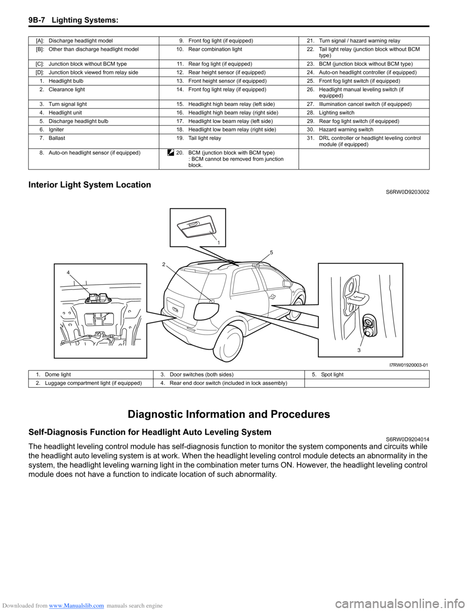
Interior Light System LocationS6RW0D9203002
Diagnostic Information and Procedures
Self-Diagnosis Function for Headlight Auto Leveling SystemS6RW0D9204014
The headlight leveling control module has self-diagnosis function to monitor the system components and circuits while
the headlight auto leveling system is at work. When the headlight leveling control module detects an abnormality in the
system, the headlight leveling warning light in the combination meter turns ON. However, the headlight leveling control
module does not have a function to indicate location of such abnormality.
[A]: Discharge headlight model 9. Front fog light (if equipped) 21. Turn signal / hazard warning relay
[B]: Other than discharge headlight model 10. Rear combination light 22. Tail light relay (junction block without BCM
type)
[C]: Junction block without BCM type 11. Rear fog light (if equipped) 23. BCM (junction block without BCM type)
[D]: Junction block viewed from relay side 12. Rear height sensor (if equipped) 24. Auto-on headlight controller (if equipped)
1. Headlight bulb 13. Front height sensor (if equipped) 25. Front fog light switch (if equipped)
2. Clearance light 14. Front fog light relay (if equipped) 26. Headlight manual leveling switch (if
equipped)
3. Turn signal light 15. Headlight high beam relay (left side) 27. Illumination cancel switch (if equipped)
4. Headlight unit 16. Headlight high beam relay (right side) 28. Lighting switch
5. Discharge headlight bulb 17. Headlight low beam relay (left side) 29. Rear fog light switch (if equipped)
6. Igniter 18. Headlight low beam relay (right side) 30. Hazard warning switch
7. Ballast 19. Tail light relay 31. DRL controller or headlight leveling control
module (if equipped)
8. Auto-on headlight sensor (if equipped) 20. BCM (junction block with BCM type)
: BCM cannot be removed from junction
block.
3 4
5
2
1
I7RW01920003-01
1. Dome light 3. Door switches (both sides) 5. Spot light
2. Luggage compartment light (if equipped) 4. Rear end door switch (included in lock assembly)
Page 1329 of 1556
Downloaded from www.Manualslib.com manuals search engine Lighting Systems: 9B-10
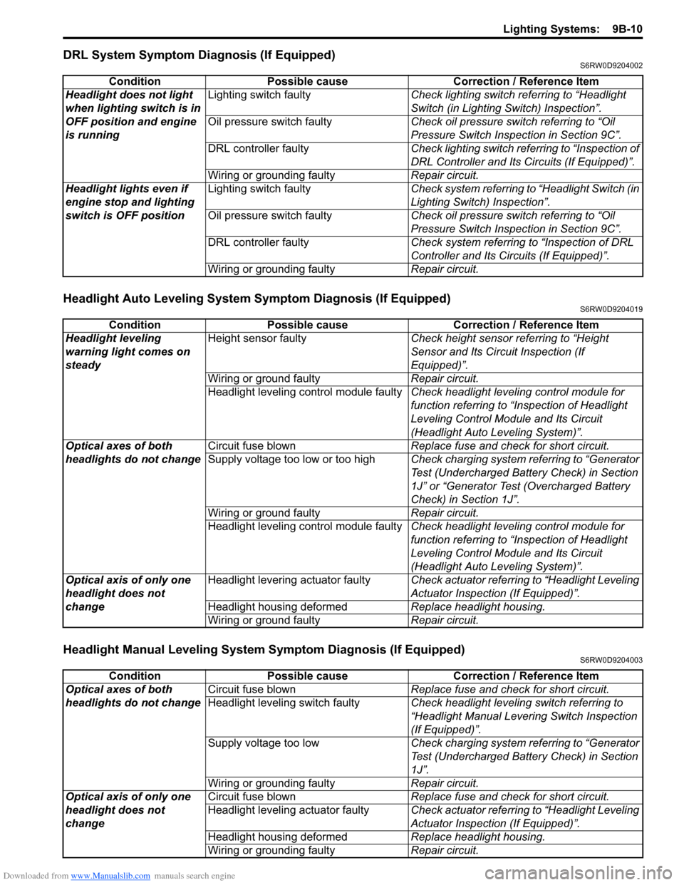
DRL System Symptom Diagnosis (If Equipped)S6RW0D9204002
Headlight Auto Leveling System Symptom Diagnosis (If Equipped)S6RW0D9204019
Headlight Manual Leveling System Symptom Diagnosis (If Equipped)S6RW0D9204003
Condition Possible cause Correction / Reference Item
Headlight does not light
when lighting switch is in
OFF position and engine
is runningLighting switch faultyCheck lighting switch referring to “Headlight
Switch (in Lighting Switch) Inspection”.
Oil pressure switch faultyCheck oil pressure switch referring to “Oil
Pressure Switch Inspection in Section 9C”.
DRL controller faultyCheck lighting switch referring to “Inspection of
DRL Controller and Its Circuits (If Equipped)”.
Wiring or grounding faultyRepair circuit.
Headlight lights even if
engine stop and lighting
switch is OFF positionLighting switch faultyCheck system referring to “Headlight Switch (in
Lighting Switch) Inspection”.
Oil pressure switch faultyCheck oil pressure switch referring to “Oil
Pressure Switch Inspection in Section 9C”.
DRL controller faultyCheck system referring to “Inspection of DRL
Controller and Its Circuits (If Equipped)”.
Wiring or grounding faultyRepair circuit.
Condition Possible cause Correction / Reference Item
Headlight leveling
warning light comes on
steadyHeight sensor faultyCheck height sensor referring to “Height
Sensor and Its Circuit Inspection (If
Equipped)”.
Wiring or ground faultyRepair circuit.
Headlight leveling control module faultyCheck headlight leveling control module for
function referring to “Inspection of Headlight
Leveling Control Module and Its Circuit
(Headlight Auto Leveling System)”.
Optical axes of both
headlights do not changeCircuit fuse blownReplace fuse and check for short circuit.
Supply voltage too low or too highCheck charging system referring to “Generator
Test (Undercharged Battery Check) in Section
1J” or “Generator Test (Overcharged Battery
Check) in Section 1J”.
Wiring or ground faultyRepair circuit.
Headlight leveling control module faultyCheck headlight leveling control module for
function referring to “Inspection of Headlight
Leveling Control Module and Its Circuit
(Headlight Auto Leveling System)”.
Optical axis of only one
headlight does not
changeHeadlight levering actuator faultyCheck actuator referring to “Headlight Leveling
Actuator Inspection (If Equipped)”.
Headlight housing deformedReplace headlight housing.
Wiring or ground faultyRepair circuit.
Condition Possible cause Correction / Reference Item
Optical axes of both
headlights do not changeCircuit fuse blownReplace fuse and check for short circuit.
Headlight leveling switch faultyCheck headlight leveling switch referring to
“Headlight Manual Levering Switch Inspection
(If Equipped)”.
Supply voltage too lowCheck charging system referring to “Generator
Test (Undercharged Battery Check) in Section
1J”.
Wiring or grounding faultyRepair circuit.
Optical axis of only one
headlight does not
changeCircuit fuse blownReplace fuse and check for short circuit.
Headlight leveling actuator faultyCheck actuator referring to “Headlight Leveling
Actuator Inspection (If Equipped)”.
Headlight housing deformedReplace headlight housing.
Wiring or grounding faultyRepair circuit.
Page 1336 of 1556
Downloaded from www.Manualslib.com manuals search engine 9B-17 Lighting Systems:
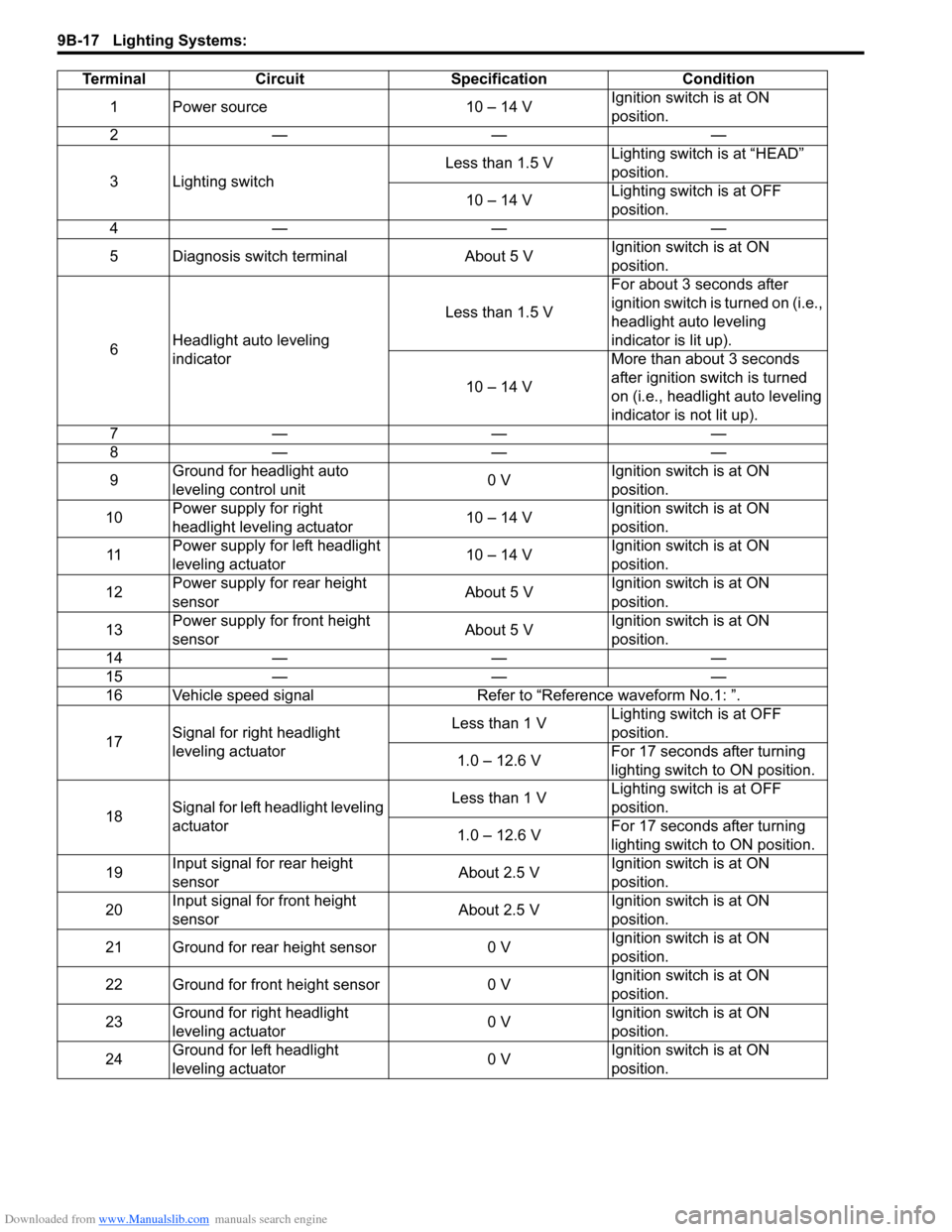
Terminal Circuit Specification Condition
1 Power source 10 – 14 VIgnition switch is at ON
position.
2———
3 Lighting switchLess than 1.5 VLighting switch is at “HEAD”
position.
10 – 14 VLighting switch is at OFF
position.
4———
5 Diagnosis switch terminal About 5 VIgnition switch is at ON
position.
6Headlight auto leveling
indicatorLess than 1.5 VFor about 3 seconds after
ignition switch is turned on (i.e.,
headlight auto leveling
indicator is lit up).
10 – 14 VMore than about 3 seconds
after ignition switch is turned
on (i.e., headlight auto leveling
indicator is not lit up).
7———
8———
9Ground for headlight auto
leveling control unit0 VIgnition switch is at ON
position.
10Power supply for right
headlight leveling actuator10 – 14 VIgnition switch is at ON
position.
11Power supply for left headlight
leveling actuator10 – 14 VIgnition switch is at ON
position.
12Power supply for rear height
sensorAbout 5 VIgnition switch is at ON
position.
13Power supply for front height
sensorAbout 5 VIgnition switch is at ON
position.
14———
15———
16 Vehicle speed signal Refer to “Reference waveform No.1: ”.
17Signal for right headlight
leveling actuatorLess than 1 VLighting switch is at OFF
position.
1.0 – 12.6 VFor 17 seconds after turning
lighting switch to ON position.
18Signal for left headlight leveling
actuatorLess than 1 VLighting switch is at OFF
position.
1.0 – 12.6 VFor 17 seconds after turning
lighting switch to ON position.
19Input signal for rear height
sensorAbout 2.5 VIgnition switch is at ON
position.
20Input signal for front height
sensorAbout 2.5 VIgnition switch is at ON
position.
21 Ground for rear height sensor 0 VIgnition switch is at ON
position.
22 Ground for front height sensor 0 VIgnition switch is at ON
position.
23Ground for right headlight
leveling actuator0 VIgnition switch is at ON
position.
24
Ground for left headlight
leveling actuator0 VIgnition switch is at ON
position.
Page 1348 of 1556
Downloaded from www.Manualslib.com manuals search engine 9B-29 Lighting Systems:
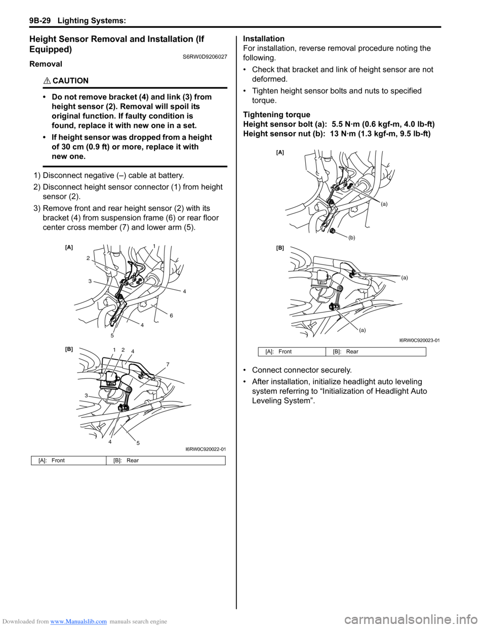
Height Sensor Removal and Installation (If
Equipped)
S6RW0D9206027
Removal
CAUTION!
• Do not remove bracket (4) and link (3) from
height sensor (2). Removal will spoil its
original function. If faulty condition is
found, replace it with new one in a set.
• If height sensor was dropped from a height
of 30 cm (0.9 ft) or more, replace it with
new one.
1) Disconnect negative (–) cable at battery.
2) Disconnect height sensor connector (1) from height
sensor (2).
3) Remove front and rear height sensor (2) with its
bracket (4) from suspension frame (6) or rear floor
center cross member (7) and lower arm (5).Installation
For installation, reverse removal procedure noting the
following.
• Check that bracket and link of height sensor are not
deformed.
• Tighten height sensor bolts and nuts to specified
torque.
Tightening torque
Height sensor bolt (a): 5.5 N·m (0.6 kgf-m, 4.0 lb-ft)
Height sensor nut (b): 13 N·m (1.3 kgf-m, 9.5 lb-ft)
• Connect connector securely.
• After installation, initialize headlight auto leveling
system referring to “Initialization of Headlight Auto
Leveling System”.
[A]: Front [B]: Rear
12
7
[B] [A]
4
3
2
6
3
5
5
1
4
4
4
I6RW0C920022-01
[A]: Front [B]: Rear
[B] [A]
(b)
(a)
(a)
(a)
I6RW0C920023-01
Page 1349 of 1556
Downloaded from www.Manualslib.com manuals search engine Lighting Systems: 9B-30
Height Sensor and Its Circuit Inspection (If
Equipped)
S6RW0D9206028
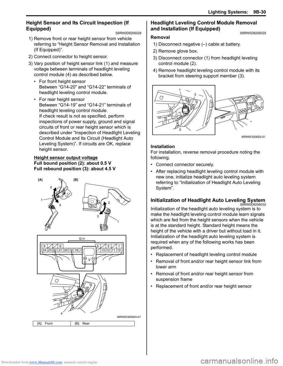
1) Remove front or rear height sensor from vehicle
referring to “Height Sensor Removal and Installation
(If Equipped)”.
2) Connect connector to height sensor.
3) Vary position of height sensor link (1) and measure
voltage between terminals of headlight leveling
control module (4) as described below.
• For front height sensor
Between “G14-20” and “G14-22” terminals of
headlight leveling control module.
• For rear height sensor
Between “G14-19” and “G14-21” terminals of
headlight leveling control module.
If check result is not as specified, perform
inspections of power supply, ground and signal
circuits of front or rear height sensor which is
described under “Inspection of Headlight Leveling
Control Module and Its Circuit (Headlight Auto
Leveling System)”. If circuits are OK, replace
height sensor.
Height sensor output voltage
Full bound position (2): about 0.5 V
Full rebound position (3): about 4.5 V
Headlight Leveling Control Module Removal
and Installation (If Equipped)
S6RW0D9206029
Removal
1) Disconnect negative (–) cable at battery.
2) Remove glove box.
3) Disconnect connector (1) from headlight leveling
control module (2).
4) Remove headlight leveling control module with its
bracket from steering support member (3).
Installation
For installation, reverse removal procedure noting the
following.
• Connect connector securely.
• After replacing headlight leveling control module with
new one, initialize headlight auto leveling system
referring to “Initialization of Headlight Auto Leveling
System”.
Initialization of Headlight Auto Leveling SystemS6RW0D9206030
Initialization of the headlight auto leveling system is to
make the headlight leveling control module learn signals
which are fed from the height sensors when the vehicle
is at the standard height. Standard height means the
height of the vehicle with a driver but without load in it.
Initialization of the headlight auto leveling system is
required when any of the following works has been
performed.
• Replacement of headlight leveling control module
• Removal of front and/or rear height sensor link from
lower arm
• Removal of front and/or rear height sensor from
suspension frame
• Replacement of front and/or rear height sensor
[A]: Front [B]: Rear
[A] [B]
4
G14
10 11 12 13 16 17 18 19 2031 5 6 9
21 22 23 24
V
2
3 1
2
3
1
I6RW0C920024-01
23 1
I6RW0C920025-01
Page 1352 of 1556
Downloaded from www.Manualslib.com manuals search engine 9B-33 Lighting Systems:
Specifications
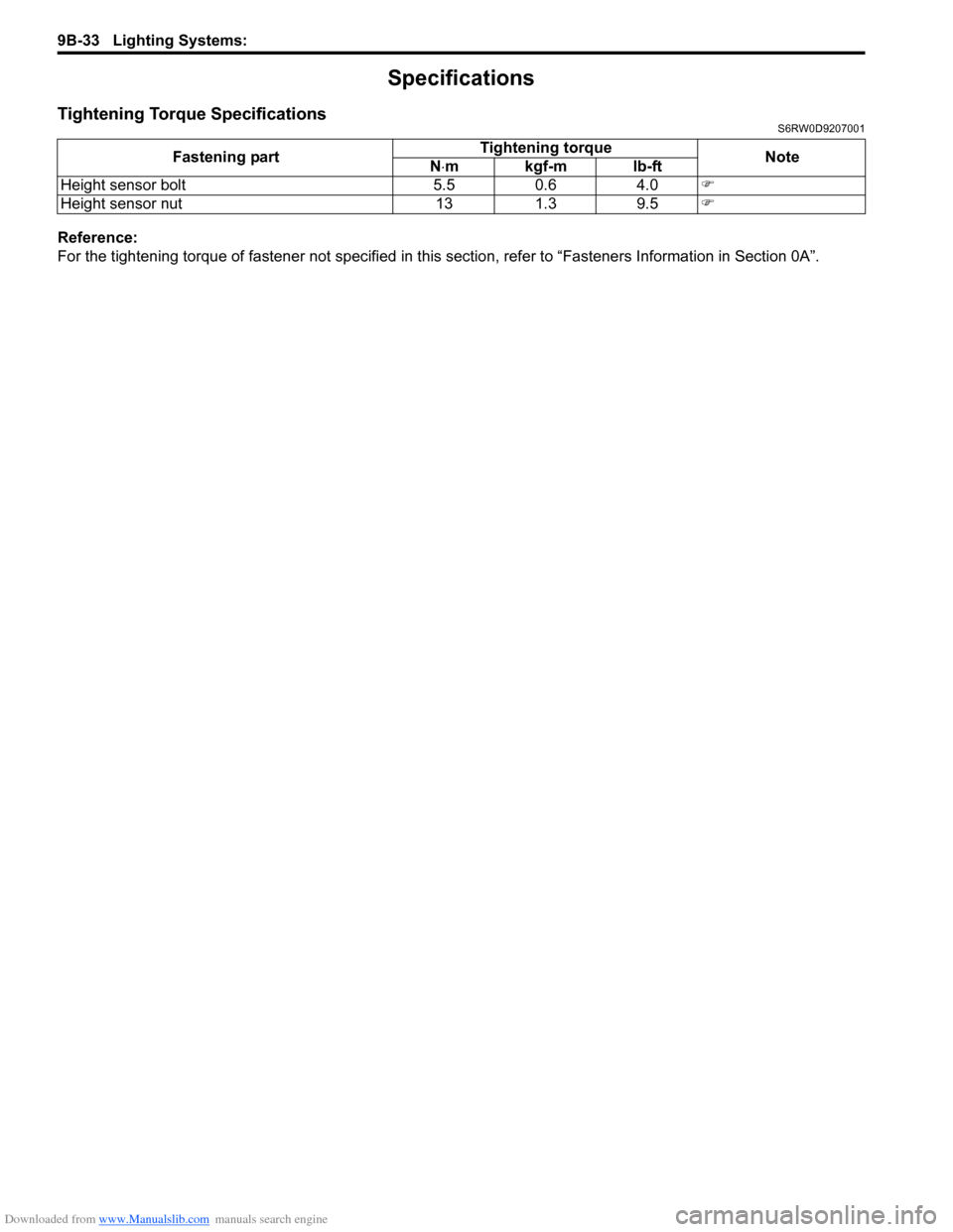
Tightening Torque SpecificationsS6RW0D9207001
Reference:
For the tightening torque of fastener not specified in this section, refer to “Fasteners Information in Section 0A”. Fastening partTightening torque
Note
N⋅mkgf-mlb-ft
Height sensor bolt 5.5 0.6 4.0�)
Height sensor nut 13 1.3 9.5�)