2006 SUZUKI SX4 Oil ring
[x] Cancel search: Oil ringPage 1374 of 1556
Downloaded from www.Manualslib.com manuals search engine 9C-22 Instrumentation / Driver Info. / Horn:
Remote Audio Control Switch Inspection (If
Equipped)
S6RW0D9306025
1) Remove driver air bag (inflator) module referring to
“Driver Air Bag (Inflator) Module Removal and
Installation in Section 8B”.
2) Disconnect remote audio control switch connector
from contact coil.
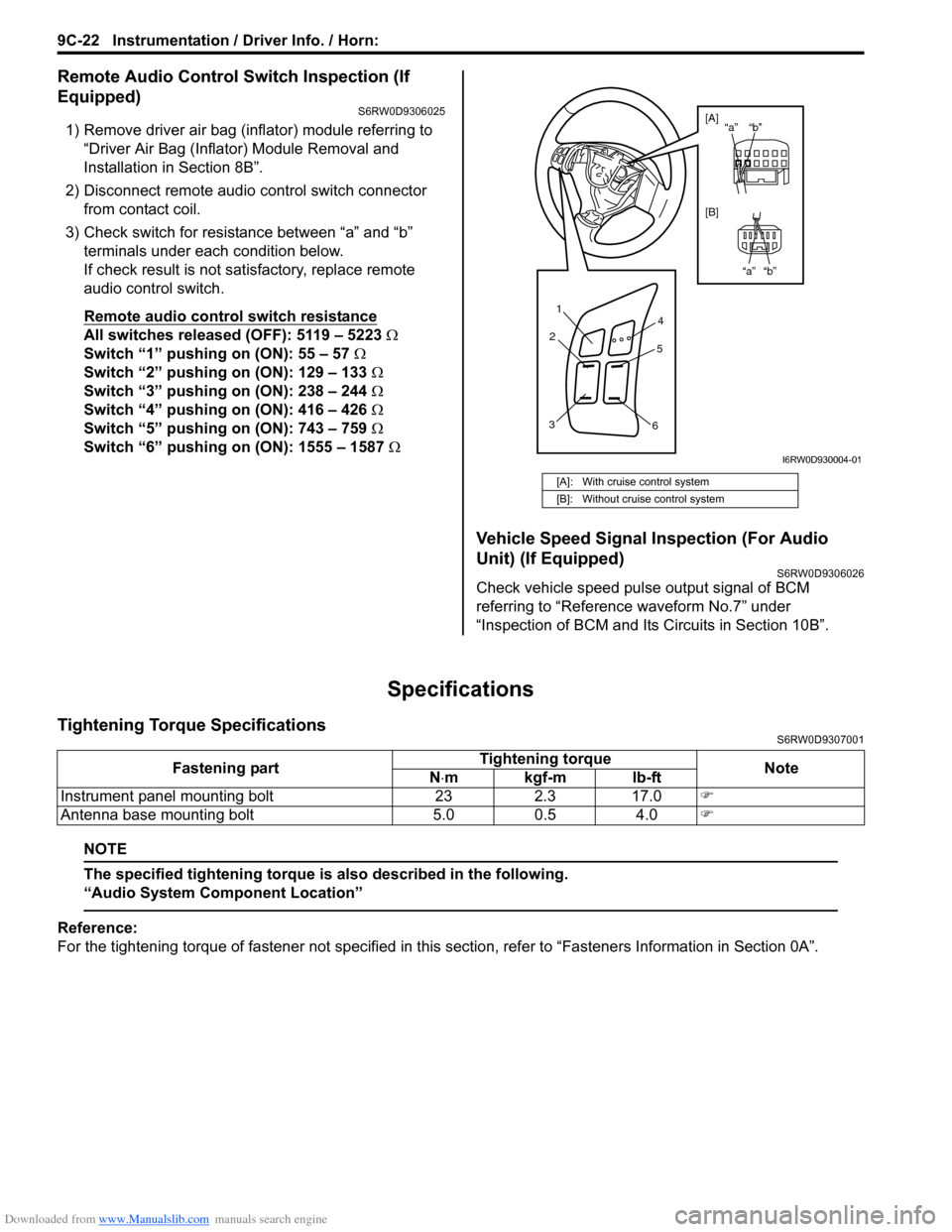
3) Check switch for resistance between “a” and “b”
terminals under each condition below.
If check result is not satisfactory, replace remote
audio control switch.
Remote audio control switch resistance
All switches released (OFF): 5119 – 5223 Ω
Switch “1” pushing on (ON): 55 – 57 Ω
Switch “2” pushing on (ON): 129 – 133 Ω
Switch “3” pushing on (ON): 238 – 244 Ω
Switch “4” pushing on (ON): 416 – 426 Ω
Switch “5” pushing on (ON): 743 – 759 Ω
Switch “6” pushing on (ON): 1555 – 1587 Ω
Vehicle Speed Signal Inspection (For Audio
Unit) (If Equipped)
S6RW0D9306026
Check vehicle speed pulse output signal of BCM
referring to “Reference waveform No.7” under
“Inspection of BCM and Its Circuits in Section 10B”.
Specifications
Tightening Torque SpecificationsS6RW0D9307001
NOTE
The specified tightening torque is also described in the following.
“Audio System Component Location”
Reference:
For the tightening torque of fastener not specified in this section, refer to “Fasteners Information in Section 0A”.
[A]: With cruise control system
[B]: Without cruise control system
1
2
34
5
6
“b” “a”
“b” “a” [A]
[B]
I6RW0D930004-01
Fastening partTightening torque
Note
N⋅mkgf-mlb-ft
Instrument panel mounting bolt 23 2.3 17.0�)
Antenna base mounting bolt 5.0 0.5 4.0�)
Page 1392 of 1556
Downloaded from www.Manualslib.com manuals search engine 9E-7 Glass / Windows / Mirrors:
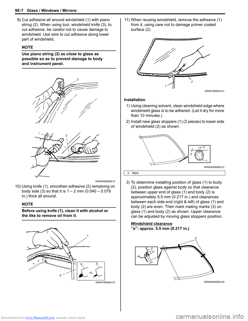
9) Cut adhesive all around windshield (1) with piano
string (2). When using tool, windshield knife (3), to
cut adhesive, be careful not to cause damage to
windshield. Use wire to cut adhesive along lower
part of windshield.
NOTE
Use piano string (2) as close to glass as
possible so as to prevent damage to body
and instrument panel.
10) Using knife (1), smoothen adhesive (2) remaining on
body side (3) so that it is 1 – 2 mm (0.040 – 0.078
in.) thick all around.
NOTE
Before using knife (1), clean it with alcohol or
the like to remove oil from it.
11) When reusing windshield, remove the adhesive (1)
from it, using care not to damage primer coated
surface (2).
Installation
1) Using cleaning solvent, clean windshield edge where
windshield glass is to be adhered. (Let it dry for more
than 10 minutes.)
2) Install new glass stoppers (1) (2 pieces) to lower side
of windshield (2) as shown.
3) To determine installing position of glass (1) to body
(2), position glass against body so that clearance
between upper end of glass (1) and body (2) is
approximately 5.5 mm (0.217 in.) and clearances
between each side end (right & left) of glass (1) and
body (2) are even. Then mark mating marks (3) on
glass (1) and body (2) as shown. Upper clearance
can be adjusted by moving glass stoppers position.
Windshield clearance
“a”: approx. 5.5 mm (0.217 in.)
I3RH0A950006-01
I2RH01950042-01
3. Mark
I2RH01950043-01
1
3
2
I5RW0A950002-01
2
1“a”
3
I5RW0A950003-02
Page 1404 of 1556
Downloaded from www.Manualslib.com manuals search engine 9E-19 Glass / Windows / Mirrors:
Rear End Door Window Defogger Relay
Inspection
S6RW0D9506018
1) Disconnect negative (–) cable from battery.
2) Remove junction block for inspection of rear end
door window defogger relay.
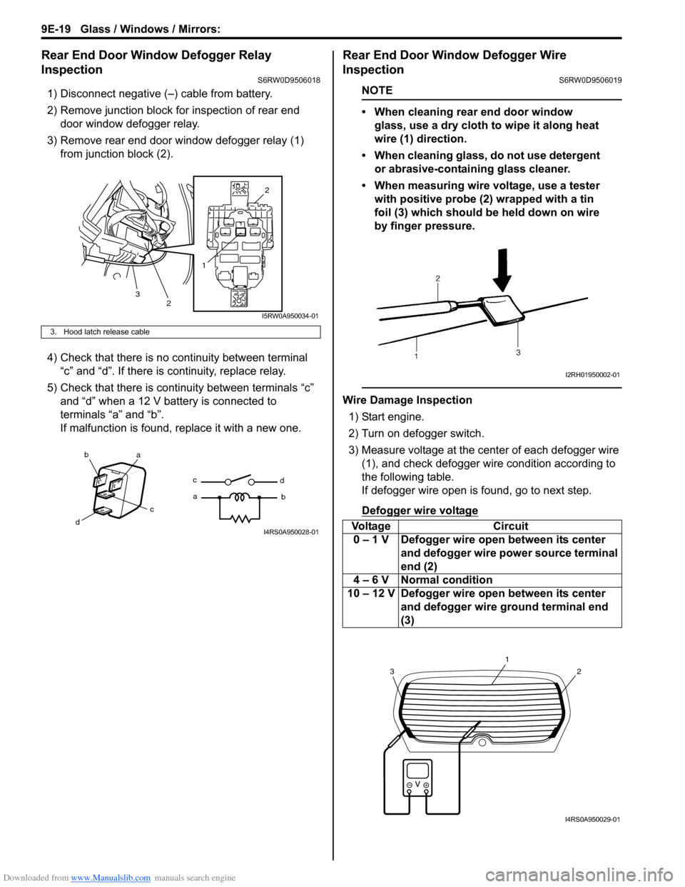
3) Remove rear end door window defogger relay (1)
from junction block (2).
4) Check that there is no continuity between terminal
“c” and “d”. If there is continuity, replace relay.
5) Check that there is continuity between terminals “c”
and “d” when a 12 V battery is connected to
terminals “a” and “b”.
If malfunction is found, replace it with a new one.
Rear End Door Window Defogger Wire
Inspection
S6RW0D9506019
NOTE
• When cleaning rear end door window
glass, use a dry cloth to wipe it along heat
wire (1) direction.
• When cleaning glass, do not use detergent
or abrasive-containing glass cleaner.
• When measuring wire voltage, use a tester
with positive probe (2) wrapped with a tin
foil (3) which should be held down on wire
by finger pressure.
Wire Damage Inspection
1) Start engine.
2) Turn on defogger switch.
3) Measure voltage at the center of each defogger wire
(1), and check defogger wire condition according to
the following table.
If defogger wire open is found, go to next step.
Defogger wire voltage
3. Hood latch release cable
12
2
3
I5RW0A950034-01
ba
c
dc
ad
bI4RS0A950028-01Voltage Circuit
0 – 1 V Defogger wire open between its center
and defogger wire power source terminal
end (2)
4 – 6 V Normal condition
10 – 12 V Defogger wire open between its center
and defogger wire ground terminal end
(3)
I2RH01950002-01
2
1
3
I4RS0A950029-01
Page 1405 of 1556
Downloaded from www.Manualslib.com manuals search engine Glass / Windows / Mirrors: 9E-20
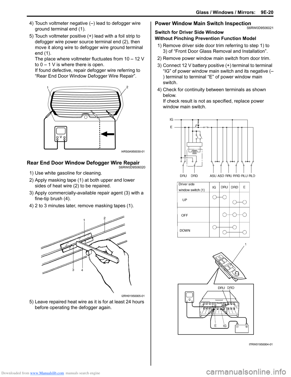
4) Touch voltmeter negative (–) lead to defogger wire
ground terminal end (1).
5) Touch voltmeter positive (+) lead with a foil strip to
defogger wire power source terminal end (2), then
move it along wire to defogger wire ground terminal
end (1).
The place where voltmeter fluctuates from 10 – 12 V
to 0 – 1 V is where there is open.
If found defective, repair defogger wire referring to
“Rear End Door Window Defogger Wire Repair”.
Rear End Door Window Defogger Wire RepairS6RW0D9506020
1) Use white gasoline for cleaning.
2) Apply masking tape (1) at both upper and lower
sides of heat wire (2) to be repaired.
3) Apply commercially-available repair agent (3) with a
fine-tip brush (4).
4) 2 to 3 minutes later, remove masking tapes (1).
5) Leave repaired heat wire as it is for at least 24 hours
before operating the defogger again.
Power Window Main Switch InspectionS6RW0D9506021
Switch for Driver Side Window
Without Pinching Prevention Function Model
1) Remove driver side door trim referring to step 1) to
3) of “Front Door Glass Removal and Installation”.
2) Remove power window main switch from door trim.
3) Connect 12 V battery positive (+) terminal to terminal
“IG” of power window main switch and its negative (–
) terminal to terminal “E” of power window main
switch.
4) Check for continuity between terminals as shown
below.
If check result is not as specified, replace power
window main switch.
21
I4RS0A950030-01
I2RH01950005-01
I7RW01950004-01
Page 1443 of 1556
Downloaded from www.Manualslib.com manuals search engine Hood / Fenders / Doors: 9J-7
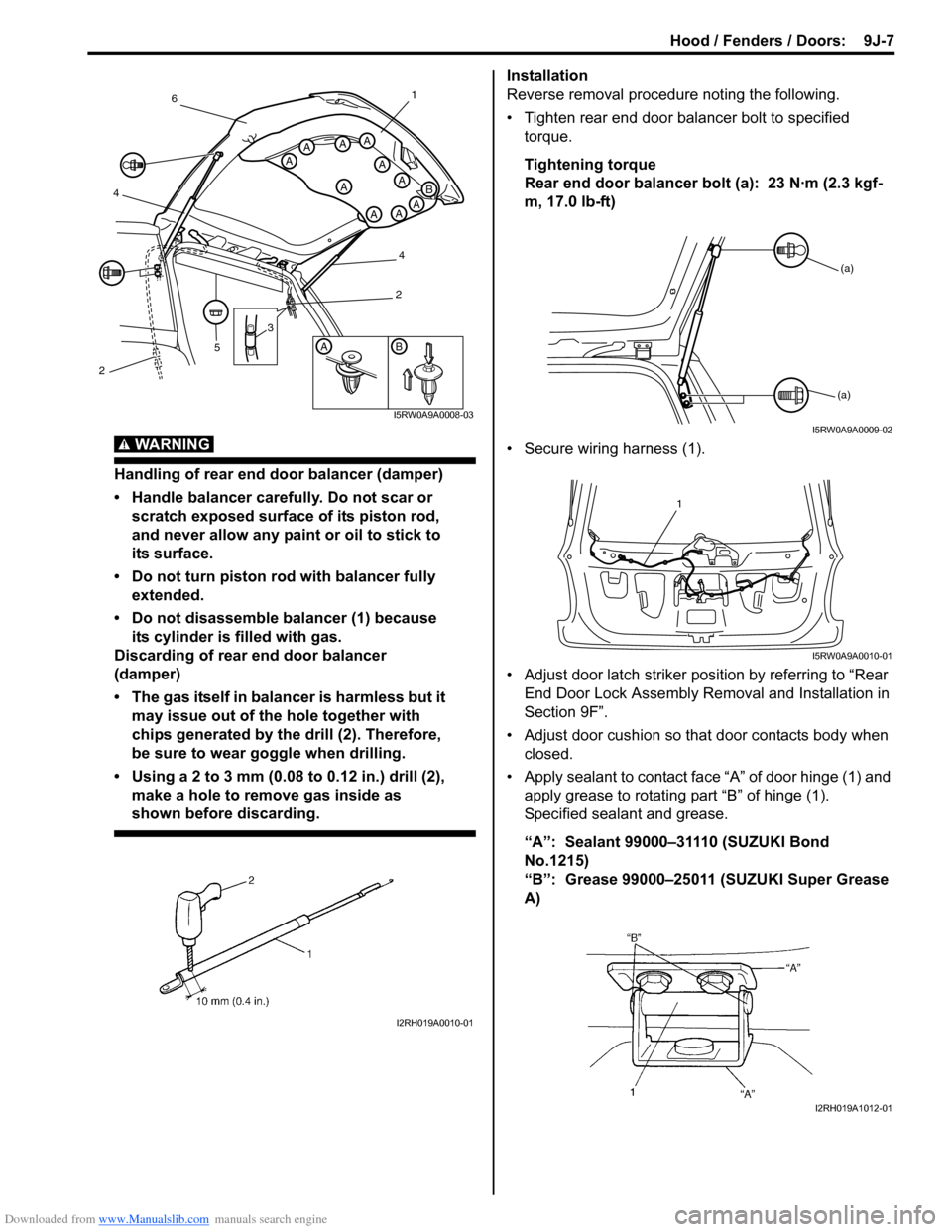
WARNING!
Handling of rear end door balancer (damper)
• Handle balancer carefully. Do not scar or
scratch exposed surface of its piston rod,
and never allow any paint or oil to stick to
its surface.
• Do not turn piston rod with balancer fully
extended.
• Do not disassemble balancer (1) because
its cylinder is filled with gas.
Discarding of rear end door balancer
(damper)
• The gas itself in balancer is harmless but it
may issue out of the hole together with
chips generated by the drill (2). Therefore,
be sure to wear goggle when drilling.
• Using a 2 to 3 mm (0.08 to 0.12 in.) drill (2),
make a hole to remove gas inside as
shown before discarding.
Installation
Reverse removal procedure noting the following.
• Tighten rear end door balancer bolt to specified
torque.
Tightening torque
Rear end door balancer bolt (a): 23 N·m (2.3 kgf-
m, 17.0 lb-ft)
• Secure wiring harness (1).
• Adjust door latch striker position by referring to “Rear
End Door Lock Assembly Removal and Installation in
Section 9F”.
• Adjust door cushion so that door contacts body when
closed.
• Apply sealant to contact face “A” of door hinge (1) and
apply grease to rotating part “B” of hinge (1).
Specified sealant and grease.
“A”: Sealant 99000–31110 (SUZUKI Bond
No.1215)
“B”: Grease 99000–25011 (SUZUKI Super Grease
A)
AB
A
A
A
A
AAA
AAA
B
3
5
461
4
2
2
I5RW0A9A0008-03
I2RH019A0010-01
(a)
(a)
I5RW0A9A0009-02
1
I5RW0A9A0010-01
I2RH019A1012-01
Page 1474 of 1556
Downloaded from www.Manualslib.com manuals search engine 10B-1 Body Electrical Control System:
Control Systems
Body Electrical Control System
Precautions
Precautions in Diagnosing TroubleS6RW0DA200001
• Diagnostic information stored in BCM memory can be cleared as well as checked by using SUZUKI scan tool.
Before using scan tool, read its Operator’s (Instruction) Manual carefully to have good understanding as to what
functions are available and how to use it.
• Be sure to read “Precautions for Electrical Circuit Service in Section 00” before inspection and observe what is
written there.
• Communication of ECM, TCM (A/T model), ABS control module, 4WD control module (if equipped), keyless start
control module (if equipped), combination meter and BCM is established by CAN (Controller Area Network). For
detail of CAN communication for BCM, refer to “CAN Communication System Description”. Therefore, handle CAN
communication line with care referring to “Precaution for CAN Communication System in Section 00”.
General Description
BCM General DescriptionS6RW0DA201001
The Body electrical Control Module (BCM) is
incorporated in junction block. Do not attempt removal of
BCM from junction block as it may cause contact failure.
The BCM incorporates relays and controllers which are
used for the following systems and controls them.
• Power door lock (if equipped)
• Keyless entry (if equipped)
• Door lock function of keyless start system (if
equipped)
• Rear wiper
• Combination meter
• Interior light• Warning buzzer
• Rear end door window defogger and door mirror
heater (if equipped)
• Rear end door opener (if equipped)
• Theft deterrent light
Also, the BCM has a function to cause the interior light
and open door warning light in the combination meter to
turn off when any door is left open for longer than 15
minutes to reduce wasteful battery consumption.
In addition, it is possible to check operation of actuator
which is controlled by BCM by using the output test
function of SUZUKI scan tool to operate actuator
simulatively.
CAN Communication System DescriptionS6RW0DA201002
Refer to “CAN Communication System Description in Section 1A” for CAN communication system description.
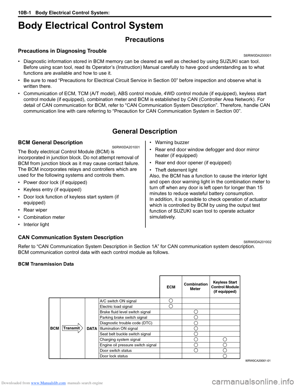
BCM communication control data with each control module as follows.
BCM Transmission Data
A/C switch ON signal
Electric load signal
Brake fluid level switch signal
Parking brake switch signal
Diagnostic trouble code (DTC)
Illumination ON signal
Seat belt buckle switch signal
Charging system signal
Engine oil pressure switch signal
Door switch status
Door lock statusECMKeyless Start
Control Module
(if equipped) Combination
Meter
BCMTransmit
DATA
I6RW0CA20001-01
Page 1504 of 1556
Downloaded from www.Manualslib.com manuals search engine 10C-2 Immobilizer Control System:
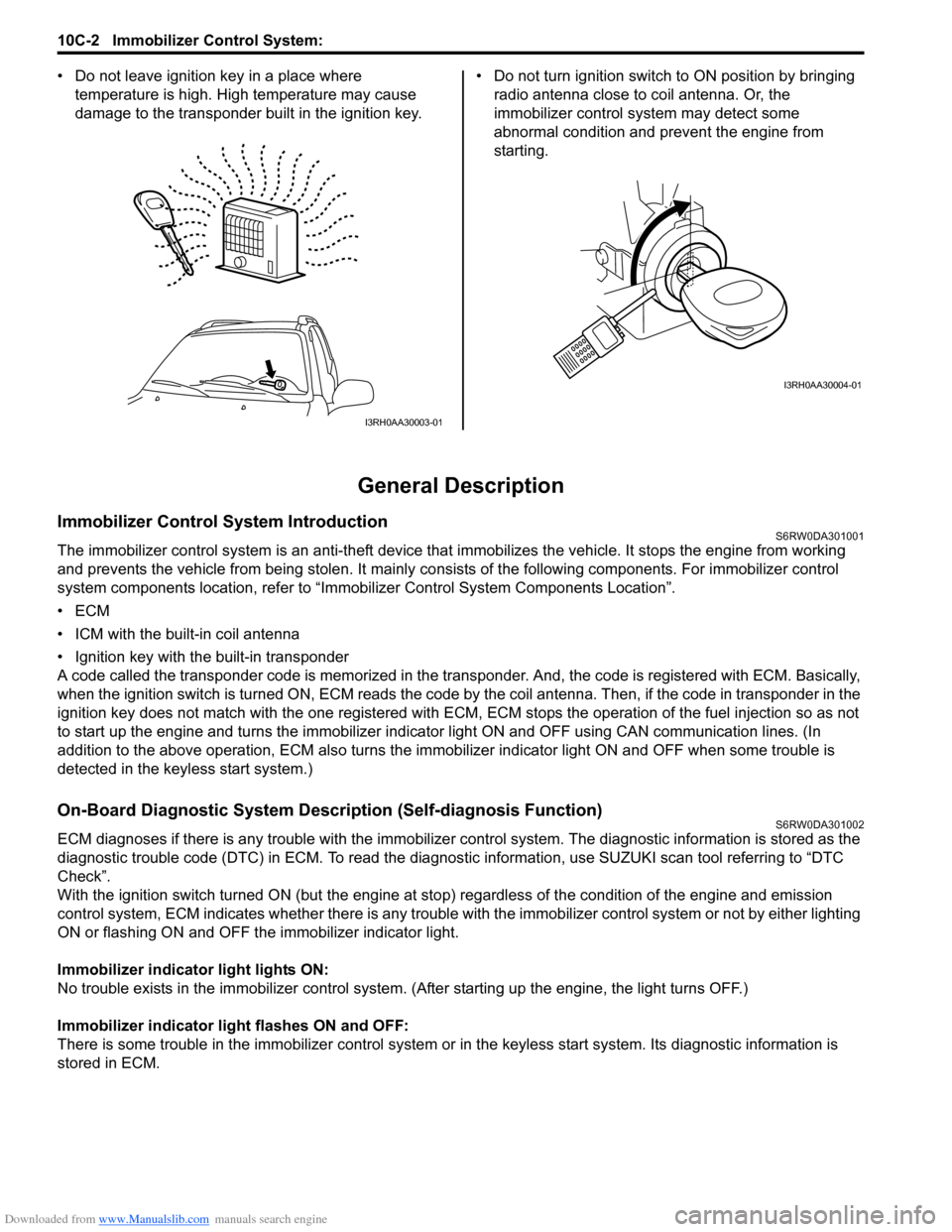
• Do not leave ignition key in a place where
temperature is high. High temperature may cause
damage to the transponder built in the ignition key.• Do not turn ignition switch to ON position by bringing
radio antenna close to coil antenna. Or, the
immobilizer control system may detect some
abnormal condition and prevent the engine from
starting.
General Description
Immobilizer Control System IntroductionS6RW0DA301001
The immobilizer control system is an anti-theft device that immobilizes the vehicle. It stops the engine from working
and prevents the vehicle from being stolen. It mainly consists of the following components. For immobilizer control
system components location, refer to “Immobilizer Control System Components Location”.
•ECM
• ICM with the built-in coil antenna
• Ignition key with the built-in transponder
A code called the transponder code is memorized in the transponder. And, the code is registered with ECM. Basically,
when the ignition switch is turned ON, ECM reads the code by the coil antenna. Then, if the code in transponder in the
ignition key does not match with the one registered with ECM, ECM stops the operation of the fuel injection so as not
to start up the engine and turns the immobilizer indicator light ON and OFF using CAN communication lines. (In
addition to the above operation, ECM also turns the immobilizer indicator light ON and OFF when some trouble is
detected in the keyless start system.)
On-Board Diagnostic System Description (Self-diagnosis Function)S6RW0DA301002
ECM diagnoses if there is any trouble with the immobilizer control system. The diagnostic information is stored as the
diagnostic trouble code (DTC) in ECM. To read the diagnostic information, use SUZUKI scan tool referring to “DTC
Check”.
With the ignition switch turned ON (but the engine at stop) regardless of the condition of the engine and emission
control system, ECM indicates whether there is any trouble with the immobilizer control system or not by either lighting
ON or flashing ON and OFF the immobilizer indicator light.
Immobilizer indicator light lights ON:
No trouble exists in the immobilizer control system. (After starting up the engine, the light turns OFF.)
Immobilizer indicator light flashes ON and OFF:
There is some trouble in the immobilizer control system or in the keyless start system. Its diagnostic information is
stored in ECM.
I3RH0AA30003-01
I3RH0AA30004-01
Page 1529 of 1556
Downloaded from www.Manualslib.com manuals search engine Keyless Start System: 10E-7
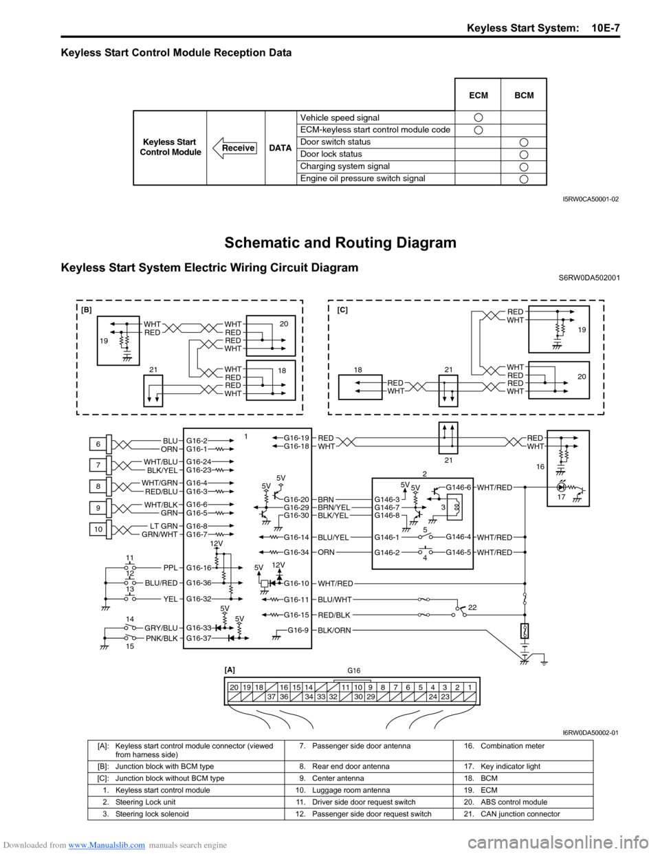
Keyless Start Control Module Reception Data
Schematic and Routing Diagram
Keyless Start System Electric Wiring Circuit DiagramS6RW0DA502001
Vehicle speed signal
ECM-keyless start control module code
Door switch status
Door lock status
Charging system signal
Engine oil pressure switch signalECM BCM
DATA
ReceiveKeyless Start
Control Module
I5RW0CA50001-02
BLK/ORNG16-9
G16-15
G16-14
G16-37G16-33
G16-16
G16-20G16-29G16-30
G16-36
G16-32
G16-10
G16-34
G16-11BLU/WHT
WHT/RED
WHT/RED
PNK/BLKGRY/BLU
BLU/RED
YEL
PPL
RED/BLK
5V5V 5V5V
5V5V
5V12V 12V
G16-2G16-1BLU
ORNWHTREDWHTREDG16-18G16-19
BLU/YEL
ORN
G16-24G16-23
BLK/YEL WHT/BLU
G16-7
GRN/WHTLT GRNG16-8
G16-5G16-6
GRN WHT/BLK
G16-4G16-3 WHT/GRN
RED/BLU
BLK/YELBRN/YELBRNG146-3
G146-1
G146-2G146-5
G146-4
G146-6
G146-7G146-8
WHT/RED
WHT/RED
G16[A]
1 2 3 4 5 6 7 8 9 10 11 14 15 16
36 34 33 32 30 29 24 23 37 18 19 20
WHTRED
WHT
WHT
RED
RED
WHTRED
6
7
8
9
10
11
12
13
14
15118
21
21
2
3
5
419
20
16
17
22
WHTRED
WHTREDWHTRED
18 1920WHTRED
WHTRED
21
[B][C]
I6RW0DA50002-01
[A]: Keyless start control module connector (viewed
from harness side)7. Passenger side door antenna 16. Combination meter
[B]: Junction block with BCM type 8. Rear end door antenna 17. Key indicator light
[C]: Junction block without BCM type 9. Center antenna 18. BCM
1. Keyless start control module 10. Luggage room antenna 19. ECM
2. Steering Lock unit 11. Driver side door request switch 20. ABS control module
3. Steering lock solenoid 12. Passenger side door request switch 21. CAN junction connector