2006 SUZUKI SX4 wiring system
[x] Cancel search: wiring systemPage 1330 of 1556
Downloaded from www.Manualslib.com manuals search engine 9B-11 Lighting Systems:
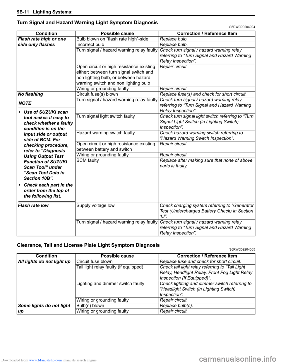
Turn Signal and Hazard Warning Light Symptom DiagnosisS6RW0D9204004
Clearance, Tail and License Plate Light Symptom DiagnosisS6RW0D9204005
Condition Possible cause Correction / Reference Item
Flash rate high or one
side only flashesBulb blown on “flash rate high”-sideReplace bulb.
Incorrect bulbReplace bulb.
Turn signal / hazard warning relay faultyCheck turn signal / hazard warning relay
referring to “Turn Signal and Hazard Warning
Relay Inspection”.
Open circuit or high resistance existing
either; between turn signal switch and
non lighting bulb, or between hazard
warning switch and non lighting bulbRepair circuit.
Wiring or grounding faultyRepair circuit.
No flashing
NOTE
• Use of SUZUKI scan
tool makes it easy to
check whether a faulty
condition is on the
input side or output
side of BCM. For
checking procedure,
refer to “Diagnosis
Using Output Test
Function of SUZUKI
Scan Tool” under
“Scan Tool Data in
Section 10B”.
• Check each part in the
order from the top of
the following list.
Circuit fuse(s) blownReplace fuse(s) and check for short circuit.
Turn signal / hazard warning relay faultyCheck turn signal / hazard warning relay
referring to “Turn Signal and Hazard Warning
Relay Inspection”.
Turn signal light switch faultyCheck turn signal light switch referring to “Turn
Signal Light Switch (in Lighting Switch)
Inspection”.
Hazard warning switch faultyCheck hazard warning switch referring to
“Hazard Warning Switch Inspection”.
Open circuit or high resistance existing
between battery and switchRepair circuit.
Wiring or grounding faultyRepair circuit.
BCM faultyReplace after making sure that none of above
parts is faulty.
Flash rate lowSupply voltage lowCheck charging system referring to “Generator
Test (Undercharged Battery Check) in Section
1J”.
Turn signal / hazard warning relay faultyCheck turn signal / hazard warning relay
referring to “Turn Signal and Hazard Warning
Relay Inspection”.
Condition Possible cause Correction / Reference Item
All lights do not light upCircuit fuse blownReplace fuse and check for short circuit.
Tail light relay faulty (if equipped)Check tail light relay referring to “Tail Light
Relay, Headlight Relay, Front Fog Light Relay
Inspection (If Equipped)”.
Lighting and dimmer switch faultyCheck lighting and dimmer switch referring to
“Headlight Switch (in Lighting Switch)
Inspection”.
Wiring or grounding faultyRepair circuit.
Some lights do not light
upBulb(s) blownReplace bulb(s).
Wiring or grounding faultyRepair circuit.
Page 1331 of 1556
Downloaded from www.Manualslib.com manuals search engine Lighting Systems: 9B-12
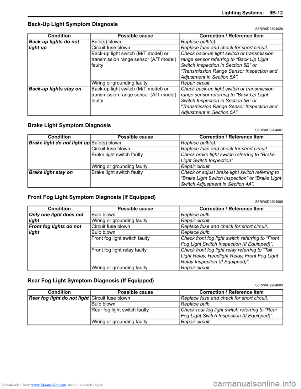
Back-Up Light Symptom DiagnosisS6RW0D9204020
Brake Light Symptom DiagnosisS6RW0D9204007
Front Fog Light Symptom Diagnosis (If Equipped)S6RW0D9204008
Rear Fog Light Symptom Diagnosis (If Equipped)S6RW0D9204009
Condition Possible cause Correction / Reference Item
Back-up lights do not
light upBulb(s) blownReplace bulb(s).
Circuit fuse blownReplace fuse and check for short circuit.
Back-up light switch (M/T model) or
transmission range sensor (A/T model)
faultyCheck back-up light switch or transmission
range sensor referring to “Back Up Light
Switch Inspection in Section 5B” or
“Transmission Range Sensor Inspection and
Adjustment in Section 5A”.
Wiring or grounding faultyRepair circuit.
Back-up lights stay onBack-up light switch (M/T model) or
transmission range sensor (A/T model)
faultyCheck back-up light switch or transmission
range sensor referring to “Back Up Light
Switch Inspection in Section 5B” or
“Transmission Range Sensor Inspection and
Adjustment in Section 5A”.
Condition Possible cause Correction / Reference Item
Brake light do not light upBulb(s) blownReplace bulb(s).
Circuit fuse blownReplace fuse and check for short circuit.
Brake light switch faultyCheck brake light switch referring to “Brake
Light Switch Inspection”.
Wiring or grounding faultyRepair circuit.
Brake light stay onBrake light switch faultyCheck or adjust brake light switch referring to
“Brake Light Switch Inspection” or “Brake Light
Switch Adjustment in Section 4A”.
Condition Possible cause Correction / Reference Item
Only one light does not
lightBulb blownReplace bulb.
Wiring or grounding faultyRepair circuit.
Front fog lights do not
lightCircuit fuse blownReplace fuse and check for short circuit.
Bulb blownReplace bulb.
Front fog light switch faultyCheck front fog light switch referring to “Front
Fog Light Switch Inspection (If Equipped)”.
Front fog light relay faultyCheck front fog light relay referring to “Tail
Light Relay, Headlight Relay, Front Fog Light
Relay Inspection (If Equipped)”.
Wiring or grounding faultyRepair circuit.
Condition Possible cause Correction / Reference Item
Rear fog light do not lightCircuit fuse blownReplace fuse and check for short circuit.
Bulb blownReplace bulb.
Rear fog light switch faultyCheck rear fog light switch referring to “Rear
Fog Light Switch Inspection (If Equipped)”.
Wiring or grounding faultyRepair circuit.
Page 1332 of 1556
Downloaded from www.Manualslib.com manuals search engine 9B-13 Lighting Systems:
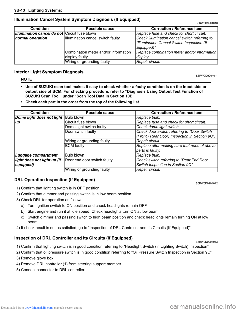
Illumination Cancel System Symptom Diagnosis (If Equipped)S6RW0D9204010
Interior Light Symptom DiagnosisS6RW0D9204011
NOTE
• Use of SUZUKI scan tool makes it easy to check whether a faulty condition is on the input side or
output side of BCM. For checking procedure, refer to “Diagnosis Using Output Test Function of
SUZUKI Scan Tool” under “Scan Tool Data in Section 10B”.
• Check each part in the order from the top of the following list.
DRL Operation Inspection (If Equipped)S6RW0D9204012
1) Confirm that lighting switch is in OFF position.
2) Confirm that dimmer and passing switch is in low beam position.
3) Check DRL for operation as follows.
a) Turn ignition switch to ON position and check headlights remain OFF.
b) Start engine and run it at idle speed. Check headlights turn ON at low beam.
c) Switch dimmer and passing switch to high beam position and check headlights remain turning ON at low
beam.
4) If check result is not as satisfied, go to “Inspection of DRL Controller and Its Circuits (If Equipped)”.
Inspection of DRL Controller and Its Circuits (If Equipped)S6RW0D9204013
1) Confirm that lighting switch is in good condition referring to “Headlight Switch (in Lighting Switch) Inspection”.
2) Confirm that oil pressure switch is in good condition referring to “Oil Pressure Switch Inspection in Section 9C”.
3) Remove glove box.
4) Remove DRL controller (1) from steering support member.
5) Connect connector to DRL controller.Condition Possible cause Correction / Reference Item
Illumination cancel do not
normal operationCircuit fuse blownReplace fuse and check for short circuit.
Illumination cancel switch faultyCheck illumination cancel switch referring to
“Illumination Cancel Switch Inspection (If
Equipped)”.
Combination meter and/or information
display faultyReplace combination meter and/or information
display.
Wiring or grounding faultyRepair circuit.
Condition Possible cause Correction / Reference Item
Dome light does not light
upBulb blownReplace bulb.
Circuit fuse blownReplace fuse and check for short circuit.
Dome light switch faultyCheck dome light switch.
Door switch faultyCheck door switch referring to “Door Switch
(Front / Rear Door) Inspection in Section 9C”.
Wiring or grounding faultyRepair circuit.
BCM faultyReplace after making sure that none of above
parts is faulty.
Luggage compartment
light does not light up (if
equipped)Bulb blownReplace bulb.
Rear end door switch faultyCheck switch referring to “Rear End Door
Switch Inspection in Section 9C”.
Wiring or grounding faultyRepair circuit.
Page 1335 of 1556
Downloaded from www.Manualslib.com manuals search engine Lighting Systems: 9B-16
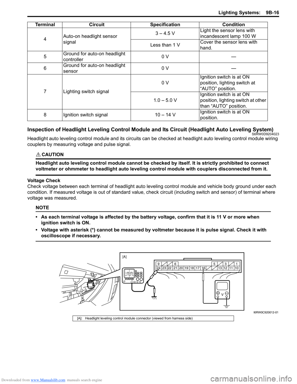
Inspection of Headlight Leveling Control Module and Its Circuit (Headlight Auto Leveling System)S6RW0D9204023
Headlight auto leveling control module and its circuits can be checked at headlight auto leveling control module wiring
couplers by measuring voltage and pulse signal.
CAUTION!
Headlight auto leveling control module cannot be checked by itself. It is strictly prohibited to connect
voltmeter or ohmmeter to headlight auto leveling control module with couplers disconnected from it.
Voltage Check
Check voltage between each terminal of headlight auto leveling control module and vehicle body ground under each
condition. If measured voltage is out of standard value, check circuit (including switch and sensor) of terminal where
voltage was measured.
NOTE
• As each terminal voltage is affected by the battery voltage, confirm that it is 11 V or more when
ignition switch is ON.
• Voltage with asterisk (*) cannot be measured by voltmeter because it is pulse signal. Check it with
oscilloscope if necessary.
4Auto-on headlight sensor
signal3 – 4.5 VLight the sensor lens with
incandescent lamp 100 W
Less than 1 VCover the sensor lens with
hand.
5Ground for auto-on headlight
controller0 V —
6Ground for auto-on headlight
sensor0 V —
7 Lighting switch signal0 VIgnition switch is at ON
position, lighting switch at
“AUTO” position.
1.0 – 5.0 VIgnition switch is at ON
position, lighting switch at other
than “AUTO” position.
8 Ignition switch signal 10 – 14 VIgnition switch is at ON
position. Terminal Circuit Specification Condition
V
10 11 12 13 16 17 18 19 2031 5 6 9
21 22 23 24
[A]
I6RW0C920012-01
[A]: Headlight leveling control module connector (viewed from harness side)
Page 1360 of 1556
Downloaded from www.Manualslib.com manuals search engine 9C-8 Instrumentation / Driver Info. / Horn:
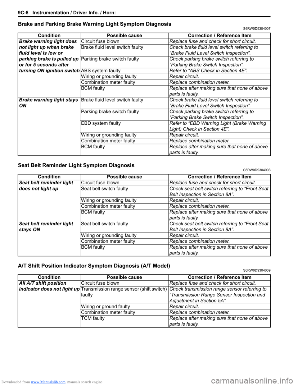
Brake and Parking Brake Warning Light Symptom DiagnosisS6RW0D9304007
Seat Belt Reminder Light Symptom DiagnosisS6RW0D9304008
A/T Shift Position Indicator Symptom Diagnosis (A/T Model)S6RW0D9304009
Condition Possible cause Correction / Reference Item
Brake warning light does
not light up when brake
fluid level is low or
parking brake is pulled up
or for 5 seconds after
turning ON ignition switchCircuit fuse blownReplace fuse and check for short circuit.
Brake fluid level switch faultyCheck brake fluid level switch referring to
“Brake Fluid Level Switch Inspection”.
Parking brake switch faultyCheck parking brake switch referring to
“Parking Brake Switch Inspection”.
ABS system faultyRefer to “ABS Check in Section 4E”.
Wiring or grounding faultyRepair circuit.
Combination meter faultyReplace combination meter.
BCM faultyReplace after making sure that none of above
parts is faulty.
Brake warning light stays
ONBrake fluid level switch faultyCheck brake fluid level switch referring to
“Brake Fluid Level Switch Inspection”.
Parking brake switch faultyCheck parking brake switch referring to
“Parking Brake Switch Inspection”.
EBD system faultyRefer to “EBD Warning Light (Brake Warning
Light) Check in Section 4E”.
Wiring or grounding faultyRepair circuit.
Combination meter faultyReplace combination meter.
BCM faultyReplace after making sure that none of above
parts is faulty.
Condition Possible cause Correction / Reference Item
Seat belt reminder light
does not light upCircuit fuse blownReplace fuse and check for short circuit.
Seat belt switch faultyCheck seat belt switch referring to “Front Seat
Belt Inspection in Section 8A”.
Wiring or grounding faultyRepair circuit.
Combination meter faultyReplace combination meter.
BCM faultyReplace after making sure that none of above
parts is faulty.
Seat belt reminder light
stays ONSeat belt switch faultyCheck seat belt switch referring to “Front Seat
Belt Inspection in Section 8A”.
Wiring or grounding faultyRepair circuit.
Combination meter faultyReplace combination meter.
BCM faultyReplace after making sure that none of above
parts is faulty.
Condition Possible cause Correction / Reference Item
All A/T shift position
indicator does not light upCircuit fuse blownReplace fuse and check for short circuit.
Transmission range sensor (shift switch)
faultyCheck transmission range sensor referring to
“Transmission Range Sensor Inspection and
Adjustment in Section 5A”.
Wiring or ground faultyRepair circuit.
Combination meter faultyReplace combination meter.
TCM faultyReplace after making sure that none of above
parts is faulty.
Page 1361 of 1556
Downloaded from www.Manualslib.com manuals search engine Instrumentation / Driver Info. / Horn: 9C-9
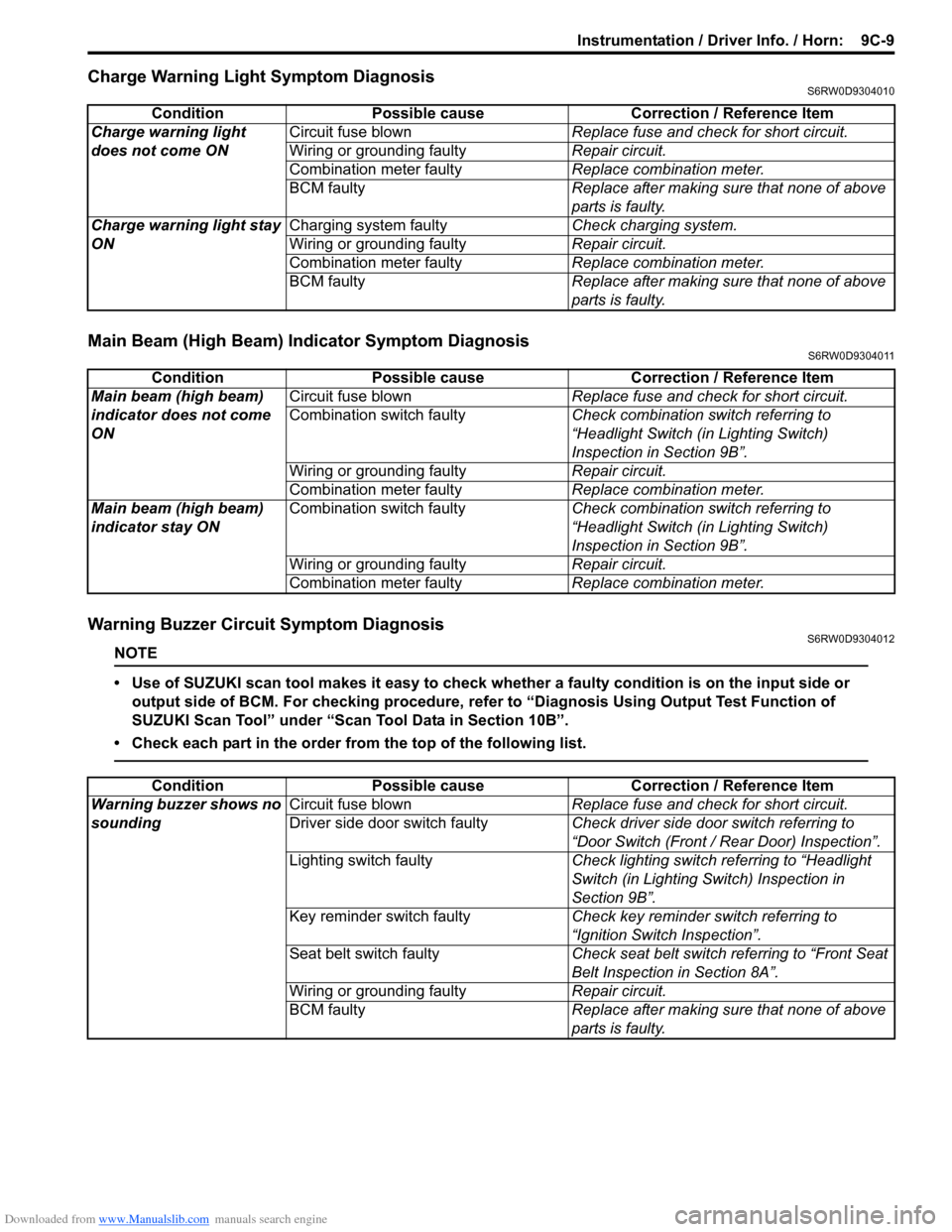
Charge Warning Light Symptom DiagnosisS6RW0D9304010
Main Beam (High Beam) Indicator Symptom DiagnosisS6RW0D9304011
Warning Buzzer Circuit Symptom DiagnosisS6RW0D9304012
NOTE
• Use of SUZUKI scan tool makes it easy to check whether a faulty condition is on the input side or
output side of BCM. For checking procedure, refer to “Diagnosis Using Output Test Function of
SUZUKI Scan Tool” under “Scan Tool Data in Section 10B”.
• Check each part in the order from the top of the following list.
Condition Possible cause Correction / Reference Item
Charge warning light
does not come ONCircuit fuse blownReplace fuse and check for short circuit.
Wiring or grounding faultyRepair circuit.
Combination meter faultyReplace combination meter.
BCM faulty Replace after making sure that none of above
parts is faulty.
Charge warning light stay
ONCharging system faultyCheck charging system.
Wiring or grounding faultyRepair circuit.
Combination meter faultyReplace combination meter.
BCM faulty Replace after making sure that none of above
parts is faulty.
Condition Possible cause Correction / Reference Item
Main beam (high beam)
indicator does not come
ONCircuit fuse blownReplace fuse and check for short circuit.
Combination switch faultyCheck combination switch referring to
“Headlight Switch (in Lighting Switch)
Inspection in Section 9B”.
Wiring or grounding faultyRepair circuit.
Combination meter faultyReplace combination meter.
Main beam (high beam)
indicator stay ONCombination switch faultyCheck combination switch referring to
“Headlight Switch (in Lighting Switch)
Inspection in Section 9B”.
Wiring or grounding faultyRepair circuit.
Combination meter faultyReplace combination meter.
Condition Possible cause Correction / Reference Item
Warning buzzer shows no
soundingCircuit fuse blownReplace fuse and check for short circuit.
Driver side door switch faultyCheck driver side door switch referring to
“Door Switch (Front / Rear Door) Inspection”.
Lighting switch faultyCheck lighting switch referring to “Headlight
Switch (in Lighting Switch) Inspection in
Section 9B”.
Key reminder switch faultyCheck key reminder switch referring to
“Ignition Switch Inspection”.
Seat belt switch faultyCheck seat belt switch referring to “Front Seat
Belt Inspection in Section 8A”.
Wiring or grounding faultyRepair circuit.
BCM faultyReplace after making sure that none of above
parts is faulty.
Page 1363 of 1556
Downloaded from www.Manualslib.com manuals search engine Instrumentation / Driver Info. / Horn: 9C-11
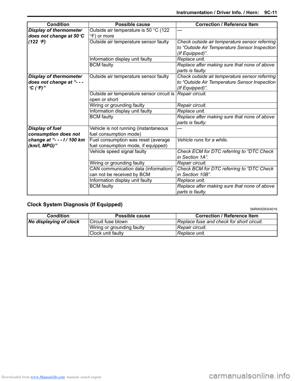
Clock System Diagnosis (If Equipped)S6RW0D9304016
Display of thermometer
does not change at 50
°C
(122
°F)Outside air temperature is 50 °C (122
°F) or more—
Outside air temperature sensor faultyCheck outside air temperature sensor referring
to “Outside Air Temperature Sensor Inspection
(If Equipped)”.
Information display unit faultyReplace unit.
BCM faultyReplace after making sure that none of above
parts is faulty.
Display of thermometer
does not change at “- - -
°C (°F)”Outside air temperature sensor faultyCheck outside air temperature sensor referring
to “Outside Air Temperature Sensor Inspection
(If Equipped)”.
Outside air temperature sensor circuit is
open or shortRepair circuit.
Wiring or grounding faultyRepair circuit.
Information display unit faultyReplace unit.
BCM faultyReplace after making sure that none of above
parts is faulty.
Display of fuel
consumption does not
change at “- - - l / 100 km
(km/l, MPG)”Vehicle is not running (instantaneous
fuel consumption mode)—
Fuel consumption was reset (average
fuel consumption mode, if equipped)Vehicle runs for a while.
Vehicle speed signal faultyCheck ECM for DTC referring to “DTC Check
in Section 1A”.
Wiring or grounding faultyRepair circuit.
CAN communication data (information)
can not be received by BCMCheck BCM for DTC referring to “DTC Check
in Section 10B”.
Information display unit faultyReplace unit.
BCM faultyReplace after making sure that none of above
parts is faulty. Condition Possible cause Correction / Reference Item
Condition Possible cause Correction / Reference Item
No displaying of clockCircuit fuse blownReplace fuse and check for short circuit.
Wiring or grounding faultyRepair circuit.
Clock unit faultyReplace unit.
Page 1364 of 1556
Downloaded from www.Manualslib.com manuals search engine 9C-12 Instrumentation / Driver Info. / Horn:
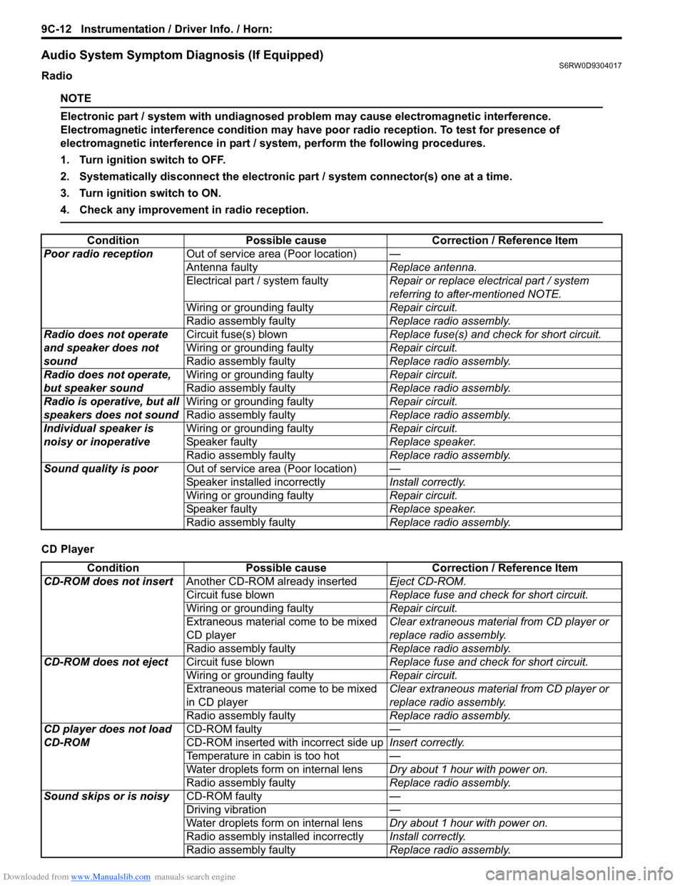
Audio System Symptom Diagnosis (If Equipped)S6RW0D9304017
Radio
NOTE
Electronic part / system with undiagnosed problem may cause electromagnetic interference.
Electromagnetic interference condition may have poor radio reception. To test for presence of
electromagnetic interference in part / system, perform the following procedures.
1. Turn ignition switch to OFF.
2. Systematically disconnect the electronic part / system connector(s) one at a time.
3. Turn ignition switch to ON.
4. Check any improvement in radio reception.
CD PlayerCondition Possible cause Correction / Reference Item
Poor radio receptionOut of service area (Poor location)—
Antenna faultyReplace antenna.
Electrical part / system faultyRepair or replace electrical part / system
referring to after-mentioned NOTE.
Wiring or grounding faultyRepair circuit.
Radio assembly faultyReplace radio assembly.
Radio does not operate
and speaker does not
soundCircuit fuse(s) blownReplace fuse(s) and check for short circuit.
Wiring or grounding faultyRepair circuit.
Radio assembly faultyReplace radio assembly.
Radio does not operate,
but speaker soundWiring or grounding faultyRepair circuit.
Radio assembly faultyReplace radio assembly.
Radio is operative, but all
speakers does not soundWiring or grounding faultyRepair circuit.
Radio assembly faultyReplace radio assembly.
Individual speaker is
noisy or inoperativeWiring or grounding faultyRepair circuit.
Speaker faultyReplace speaker.
Radio assembly faultyReplace radio assembly.
Sound quality is poorOut of service area (Poor location)—
Speaker installed incorrectlyInstall correctly.
Wiring or grounding faultyRepair circuit.
Speaker faultyReplace speaker.
Radio assembly faultyReplace radio assembly.
Condition Possible cause Correction / Reference Item
CD-ROM does not insertAnother CD-ROM already insertedEject CD-ROM.
Circuit fuse blownReplace fuse and check for short circuit.
Wiring or grounding faultyRepair circuit.
Extraneous material come to be mixed
CD playerClear extraneous material from CD player or
replace radio assembly.
Radio assembly faultyReplace radio assembly.
CD-ROM does not ejectCircuit fuse blownReplace fuse and check for short circuit.
Wiring or grounding faultyRepair circuit.
Extraneous material come to be mixed
in CD playerClear extraneous material from CD player or
replace radio assembly.
Radio assembly faultyReplace radio assembly.
CD player does not load
CD-ROMCD-ROM faulty—
CD-ROM inserted with incorrect side upInsert correctly.
Temperature in cabin is too hot—
Water droplets form on internal lensDry about 1 hour with power on.
Radio assembly faultyReplace radio assembly.
Sound skips or is noisyCD-ROM faulty—
Driving vibration—
Water droplets form on internal lensDry about 1 hour with power on.
Radio assembly installed incorrectlyInstall correctly.
Radio assembly faultyReplace radio assembly.