Page 1197 of 1556

Downloaded from www.Manualslib.com manuals search engine Wiring Systems: 9A-30
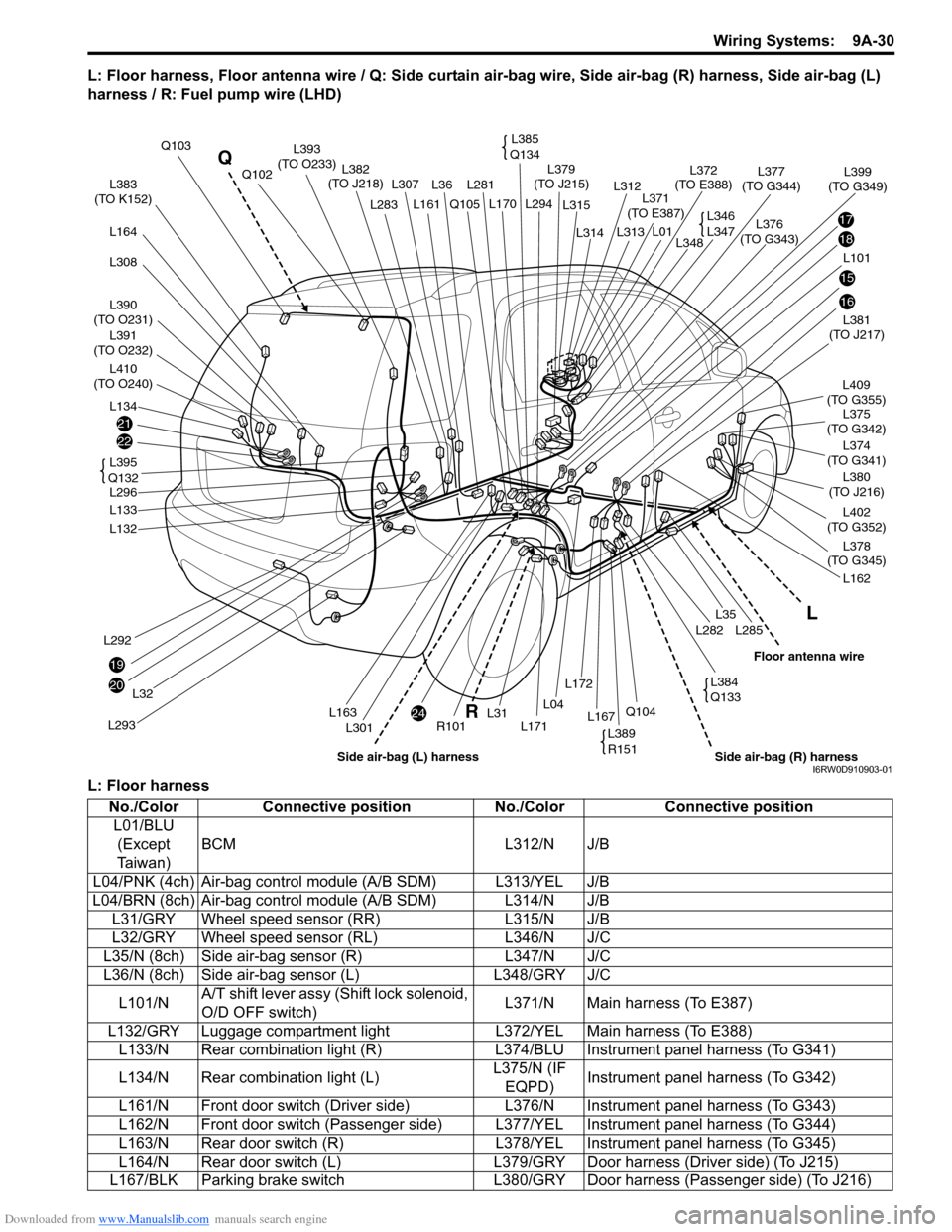
L: Floor harness, Floor antenna wire / Q: Side curtain air-bag wire, Side air-bag (R) harness, Side air-bag (L)
harness / R: Fuel pump wire (LHD)
L: Floor harness
21
22
20
24
19
17
18
15
16
L383
(TO K152)
L390
(TO O231)
L391
(TO O232)
L410
(TO O240)
L164
L308
L134
L292
L293
L32
L132
L133
L296L381
(TO J217)
L375
(TO G342)
L402
(TO G352)
L374
(TO G341)L409
(TO G355)
L380
(TO J216)
L378
(TO G345)
L162
L285L282
L35
L36L281 L307
L301
Q105
R101L171
L294 L170
L31L167Q104L04
L172
Q103
L382
(TO J218)
L376
(TO G343)L379
(TO J215)
L371
(TO E387)
L372
(TO E388)L377
(TO G344)Q102
L161L283
L163
L101L348
L399
(TO G349)
L314
L315
L312
L313
L01
L395
Q132
L385
Q134L393
(TO O233)
L346
L347
L389
R151
L384
Q133
L
R Q
Side air-bag (R) harnessFloor antenna wire
Side air-bag (L) harnessI6RW0D910903-01
No./Color Connective position No./Color Connective position
L01/BLU
(Except
Ta i w a n )BCM L312/N J/B
L04/PNK (4ch) Air-bag control module (A/B SDM) L313/YEL J/B
L04/BRN (8ch) Air-bag control module (A/B SDM) L314/N J/B
L31/GRY Wheel speed sensor (RR) L315/N J/B
L32/GRY Wheel speed sensor (RL) L346/N J/C
L35/N (8ch) Side air-bag sensor (R) L347/N J/C
L36/N (8ch) Side air-bag sensor (L) L348/GRY J/C
L101/NA/T shift lever assy (Shift lock solenoid,
O/D OFF switch)L371/N Main harness (To E387)
L132/GRY Luggage compartment light L372/YEL Main harness (To E388)
L133/N Rear combination light (R) L374/BLU Instrument panel harness (To G341)
L134/N Rear combination light (L)L375/N (IF
EQPD)Instrument panel harness (To G342)
L161/N Front door switch (Driver side) L376/N Instrument panel harness (To G343)
L162/N Front door switch (Passenger side) L377/YEL Instrument panel harness (To G344)
L163/N Rear door switch (R) L378/YEL Instrument panel harness (To G345)
L164/N Rear door switch (L) L379/GRY Door harness (Driver side) (To J215)
L167/BLK Parking brake switch L380/GRY Door harness (Passenger side) (To J216)
Page 1201 of 1556
Downloaded from www.Manualslib.com manuals search engine Wiring Systems: 9A-34
Power Supply Diagram
Power Supply DiagramS6RW0D910D001
G273
J/B
J/B
3
WHT/BLU
GRN/WHT
RED/WHT
4G1473
1
2
8
BLK
21
BLK/GRY
15A
15A15A
2314678
1E3112
WHT
1112141516
BLK/YELGRY
3
YEL/BLU
21
BLU/YEL
4
BLU
RED
WHT
WHT
WHT/RED
11
WHT/GRN
14
WHT/BLU
1516
WHT/RED
GRN
12
30A
9
WHT/BLU
9
30A
20A30A 50A40A
60A
20A15A
15A
BLK
2E3121
WHT/BLU
C282C28311
WHT
BLK
Main fuse box
Starting motor
"A-1"Generator
"A-2"
Battery
80A
50A 50A
4544
43
E3241
E32510
G2734
WHT
YEL
Individual circuit fuse box (No.1)
+B1
LOCK
ACC
ON
STACC IG1 IG2STOUT
IN
+B2
6
GRNBLU
5
Starting motor
relay
10
GRY
10
30A
E382
G33417
1
5
4
3
2
"A-1"
33
10A
I6RW0C910918-03
Page 1209 of 1556
Downloaded from www.Manualslib.com manuals search engine Wiring Systems: 9A-42
Junction Block (J/B) Connector / Fuse LayoutS6RW0D910D006
BCM side
21
65 34
43 2
121
11 14
13 15598 7
176
16 19 18 201065 43 281
7 10 912
11
34 65
2
110
11 12 13 14 15 16 17 18 19123456789
20
G272 G271
G273
BCM (J/B side connector)
3
4
1
2515
14 12
13 10
11 9 8 67
18
17202324
21
2225
252423
222120
18
1715 1413
121110
98
76
54
32
1
5
116
12 9108 72 143
I7RW01910913-02
Page 1210 of 1556
Downloaded from www.Manualslib.com manuals search engine 9A-43 Wiring Systems:
Relay side
Junction Block Inner Circuit (Overview (Except Taiwan))S6RW0D910D010
Abbreviations
543
2
1
432
1432
1432
1
4
32
1
Blower fan relay
Relay
23412 11 2
12 34 5 6 78 9
15 16 17 18 11 10 12 13 144 3561214
11
1015
721
1316
9 8 1
234
5
678 910
4
321
10
987 656
5 4 3
2
17
11 10
9 8
15
14 13
1216
987654321
13 12 11 10 17 18 16 15 14
13
14 15
16
9 10 11
128 5 6
72 3
41
321 4
E323
L314
E324L313L315 E325
HRelay
Relay
Tail light relay
38
7
6
5
2
4 1
43
5
6
12 14 11 10 15 72
1
13 16 9 8
3456
12
L312
6543
21
Flasher relay
Taiwan
I6RW0C910921-02
Abbreviation Full term Abbreviation Full term
AS Assistant (Front passenger) LP Lamp
CTR Center O/H Over head
DR Driver R/B Relay box
F-L Front L R-L Rear L
F-R Front R R-R Rear R
FR Front RR Rear
INP Instrument panel S/H Seat heater
LEV (Headlight) leveling
Page 1212 of 1556
Downloaded from www.Manualslib.com manuals search engine 9A-45 Wiring Systems:
Junction Block Inner Circuit (Detail (Except Taiwan))S6RW0D910D011
BCM (J/B side connector)
3
4
1
25
15 14 12
13 10
11 9 8 67
17
16182122 19
20
23
1234578 116
12 91034 652 1
G271 G273
G272
10
11 12 13 14 15 16 17 18 19123456789
20
345612L312
23414
3
561214 11
10
157 2 11316 9 8 6
5 4 3
2
1
7
11 10
9 8
15
14 13
1216
L313
L315 E325
2 1
123456789
15 16 17 18 11 10 12 13 14 1
234
5
678 910
E323
L314 E324
IG COIL
IG COILIG1
E323 E325E324 BCM G272G271 G273 L312 L313 L314 L315
IG COIL IG1
15A
MTR
10A
A/B
15A
2
6
5
13
J/BConnector No. / Terminal No.
MTR (IG)
A/B CONT
A/B IND
A/B IND
IG1 SIG
10AEPS AT
ABS CONT
STOP SW
STOP LP
EPI
BUL IN
BUL-LBACK H/L LVL SW
BCM IG111
6
1
4
2
A/B SIGNAL
A/B SIGNAL9
3
K-LINE
K-LINE8
12
9
14
2
3
1
2
11
8
ABS
10A
BACK
10A
ANGLE SENSOR
IG1 ABS16
8
1
(Continued)
Individual circuit fuse box No.2
(In J/B)
20
22
27
26
28
21
I6RW0C910923-01
Page 1217 of 1556
Downloaded from www.Manualslib.com manuals search engine Wiring Systems: 9A-50
Junction Block Inner Circuit (Overview (Taiwan))S6RW0D910D007
Abbreviations
Abbreviation Full term Abbreviation Full term
AS Assistant (Front passenger) LP Lamp
CTR Center O/H Over head
DR Driver R/B Relay box
F-L Front L R-L Rear L
F-R Front R R-R Rear R
FR Front RR Rear
INP Instrument panel S/H Seat heater
LEV (Headlight) leveling
Page 1219 of 1556
Downloaded from www.Manualslib.com manuals search engine Wiring Systems: 9A-52
Junction Block Inner Circuit (Detail (Taiwan))S6RW0D910D008
BCM (J/B side connector)
3
4
1
25
15 14 12
13 10
11 9 8 67
17
16182122 19
20
23
1234578 116
12 91034 652 1
G271 G273
G272
10
11 12 13 14 15 16 17 18 19123456789
20
345612L312
23414
3
561214 11
10
157 2 11316 9 8 6
5 4 3
2
1
7
11 10
9 8
15
14 13
1216
L313
L315 E325
2 1
123456789
15 16 17 18 11 10 12 13 14 1
234
5
678 910
E323
L314 E324
IG COIL
IG COILIG1
E323 E325E324 BCM G272G271 G273 L312 L313 L314 L315
IG COIL IG1
15A
MTR
10A
A/B
15A
2
6
5
13
J/BConnector No. / Terminal No.
MTR (IG)
A/B CONT
A/B IND
A/B IND
IG1 SIG
10AEPS AT
ABS CONT
STOP SW
STOP LP
EPI
BUL IN
BUL-LBACK H/L LVL SW
6
1
4
12
9
14
2
3
1
2
11
8
ABS
10A
BACK
10A
ANGLE SENSOR
IG1 ABS16
8
1
(Continued)
Individual circuit fuse box No.2
(In J/B)
20
22
27
26
28
21
I7RW01910916-04
Page 1224 of 1556

Downloaded from www.Manualslib.com manuals search engine 9A-57 Wiring Systems:
System Circuit Diagram
System Circuit DiagramS6RW0D910E001
Refer to “A-1 Cranking System Circuit Diagram”.
Refer to “A-2 Charging System Circuit Diagram”.
Refer to “A-3 Ignition System Circuit Diagram (M15A engine, M16A engine)”.
Refer to “A-3 Ignition System Circuit Diagram (J20A engine)”.
Refer to “A-4 Cooling System Circuit Diagram (M15A engine, M16A engine)”.
Refer to “A-4 Cooling System Circuit Diagram (J20A engine)”.
Refer to “A-5 Engine and A/C Control System Circuit Diagram (M15A engine)”.
Refer to “A-5 Engine and A/C Control System Circuit Diagram (M16A engine)”.
Refer to “A-5 Engine and A/C Control System Circuit Diagram (J20A engine)”.
Refer to “A-6 A/T Control System Circuit Diagram”.
Refer to “A-7 Immobilizer System Circuit Diagram”.
Refer to “A-8 Body Control System Circuit Diagram (Except Taiwan)”.
Refer to “A-8 Body Control System Circuit Diagram (Taiwan)”.
Refer to “A-10 4WD Control System (Except Taiwan)”
Refer to “B-1 Windshield Wiper and Washer Circuit Diagram”.
Refer to “B-2 Rear Wiper and Washer Circuit Diagram (Except Taiwan)”.
Refer to “B-2 Rear Wiper and Washer Circuit Diagram (Taiwan)”.
Refer to “B-3 Rear Defogger Circuit Diagram (Except Taiwan)”.
Refer to “B-3 Rear Defogger Circuit Diagram (Taiwan)”.
Refer to “B-4 Power Window Circuit Diagram”.
Refer to “B-5 Power Door Lock Circuit Diagram (Except Taiwan)”.
Refer to “B-5 Power Door Lock Circuit Diagram (Taiwan)”.
Refer to “B-6 Power Mirror Circuit Diagram (Except Taiwan)”.
Refer to “B-6 Power Mirror Circuit Diagram (Taiwan)”.
Refer to “B-7 Horn Circuit Diagram”.
Refer to “B-8 Seat Heater Circuit Diagram”.
Refer to “B-9 Keyless Start System Circuit Diagram”
Refer to “C-1 Combination Meter Circuit Diagram (Meter)”.
Refer to “C-2 Combination Meter Circuit Diagram (Indicator)”.
Refer to “C-3 Combination Meter Circuit Diagram (Warning Light)”.
Refer to “D-1 Headlight System Circuit Diagram (Except Taiwan)”.
Refer to “D-1 Headlight System Circuit Diagram (Taiwan)”.
Refer to “D-2 Position, Tail and Licence Plate Light System Circuit Diagram (Except Taiwan)”.
Refer to “D-2 Position, Tail and Licence Plate Light System Circuit Diagram (Taiwan)”.
Refer to “D-3 Front Fog Light System Circuit Diagram (Except Taiwan)”.
Refer to “D-3 Front Fog Light System Circuit Diagram (Taiwan)”.
Refer to “D-4 Illumination Light System Circuit Diagram (Except Taiwan)”.
Refer to “D-4 Illumination Light System Circuit Diagram (Taiwan)”.
Refer to “D-5 Interior Light System Circuit Diagram (Except Taiwan)”.
Refer to “D-5 Interior Light System Circuit Diagram (Taiwan)”.
Refer to “D-6 Turn Signal and Hazard Warning Light System Circuit Diagram (Except Taiwan)”.
Refer to “D-6 Turn Signal and Hazard Warning Light System Circuit Diagram (Taiwan)”.
Refer to “D-7 Brake Light System Circuit Diagram”.
Refer to “D-8 Back-Up Light System Circuit Diagram”.
Refer to “D-9 Headlight Beam Leveling System Circuit Diagram (Manual Leveling)”.
Refer to “D-10 Rear Fog Light Circuit Diagram”.
Refer to “E-1 Heater System Circuit Diagram”.
Refer to “E-2 Auto A/C System Circuit Diagram”.
Refer to “F-1 Air-Bag System Circuit Diagram (4ch)”.
Refer to “F-1 Air-Bag System Circuit Diagram (8ch)”.
Refer to “F-2 Anti-Lock Brake System Circuit Diagram”.
Refer to “F-4 Power Steering System Circuit Diagram”.
Refer to “G-1 Audio System Circuit Diagram”.
Refer to “G-2 Multi Information Display / Accessory Socket System Circuit Diagram”.
Refer to “G-4 Navigation System Circuit Diagram”.