2006 SUZUKI SX4 Ignition system
[x] Cancel search: Ignition systemPage 1021 of 1556
Downloaded from www.Manualslib.com manuals search engine Air Conditioning System: Automatic Type 7B-81
HVAC Unit Removal and InstallationS6RW0D7226003
Refer to “HVAC Unit Removal and Installation”.
Temperature Control Actuator Removal and
Installation
S6RW0D7226004
Removal
1) Disconnect negative (–) cable at battery.
2) Remove steering column hole cover from instrument
panel.
3) Remove driver side foot duct from HVAC unit.
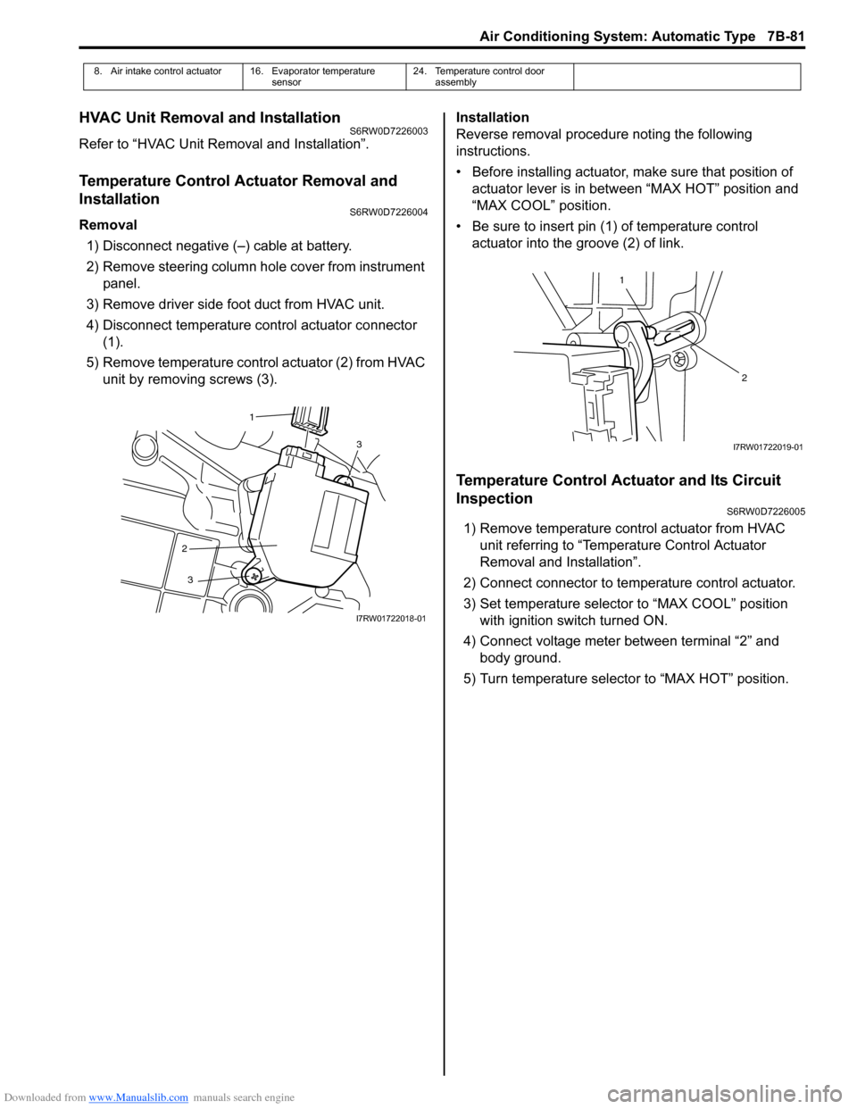
4) Disconnect temperature control actuator connector
(1).
5) Remove temperature control actuator (2) from HVAC
unit by removing screws (3).Installation
Reverse removal procedure noting the following
instructions.
• Before installing actuator, make sure that position of
actuator lever is in between “MAX HOT” position and
“MAX COOL” position.
• Be sure to insert pin (1) of temperature control
actuator into the groove (2) of link.
Temperature Control Actuator and Its Circuit
Inspection
S6RW0D7226005
1) Remove temperature control actuator from HVAC
unit referring to “Temperature Control Actuator
Removal and Installation”.
2) Connect connector to temperature control actuator.
3) Set temperature selector to “MAX COOL” position
with ignition switch turned ON.
4) Connect voltage meter between terminal “2” and
body ground.
5) Turn temperature selector to “MAX HOT” position.
8. Air intake control actuator 16. Evaporator temperature
sensor24. Temperature control door
assembly
3
2
3
1
I7RW01722018-01
1
2
I7RW01722019-01
Page 1022 of 1556
Downloaded from www.Manualslib.com manuals search engine 7B-82 Air Conditioning System: Automatic Type
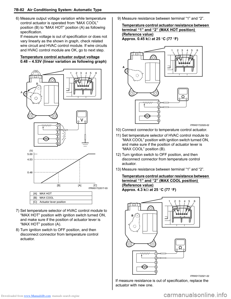
6) Measure output voltage variation while temperature
control actuator is operated from “MAX COOL”
position (B) to “MAX HOT” position (A) as following
specification.
If measure voltage is out of specification or does not
vary linearly as the shown in graph, check related
wire circuit and HVAC control module. If wire circuits
and HVAC control module are OK, go to next step.
Temperature control actuator output voltage
0.48 – 4.53V (linear variation as following graph)
7) Set temperature selector of HVAC control module to
“MAX HOT” position with ignition switch turned ON,
and make sure if the position of actuator lever is
“MAX HOT” position (A).
8) Turn ignition switch to OFF position, and then
disconnect connector from temperature control
actuator.9) Measure resistance between terminal “1” and “2”.
Temperature control actuator resistance between
terminal “1” and “2” (MAX HOT position)
(Reference value)
Approx. 0.45 kΩ at 25 °C (77 °F)
10) Connect connector to temperature control actuator.
11) Set temperature selector of HVAC control module to
“MAX COOL” position with ignition switch turned ON,
and make sure if the position of actuator lever is
“MAX COOL” position (B).
12) Turn ignition switch to OFF position, and then
disconnect connector from temperature control
actuator.
13) Measure resistance between terminal “1” and “2”.
Temperature control actuator resistance between
terminal “1” and “2” (MAX COOL position)
(Reference value)
Approx. 4.3 kΩ at 25 °C (77 °F)
If measure resistance is out of specification, replace the
actuator with new one.[A]: MAX HOT
[B]: MAX COOL
[C]: Actuator lever position
123456
6
M5
3
2
1
AB
4.53
0.48 5.00(V)
[C]
[A] [B]
I7RW01722017-03
123456
6
M5
3
2
1
A
I7RW01722020-02
123456
6
M5
3
2
1
B
I7RW01722021-02
Page 1023 of 1556
Downloaded from www.Manualslib.com manuals search engine Air Conditioning System: Automatic Type 7B-83
Air Flow Control Actuator Removal and
Installation
S6RW0D7226006
Removal
1) Disconnect negative cable at battery.
2) Remove steering column hole cover from instrument
panel.
3) Remove driver side foot duct from HVAC unit.
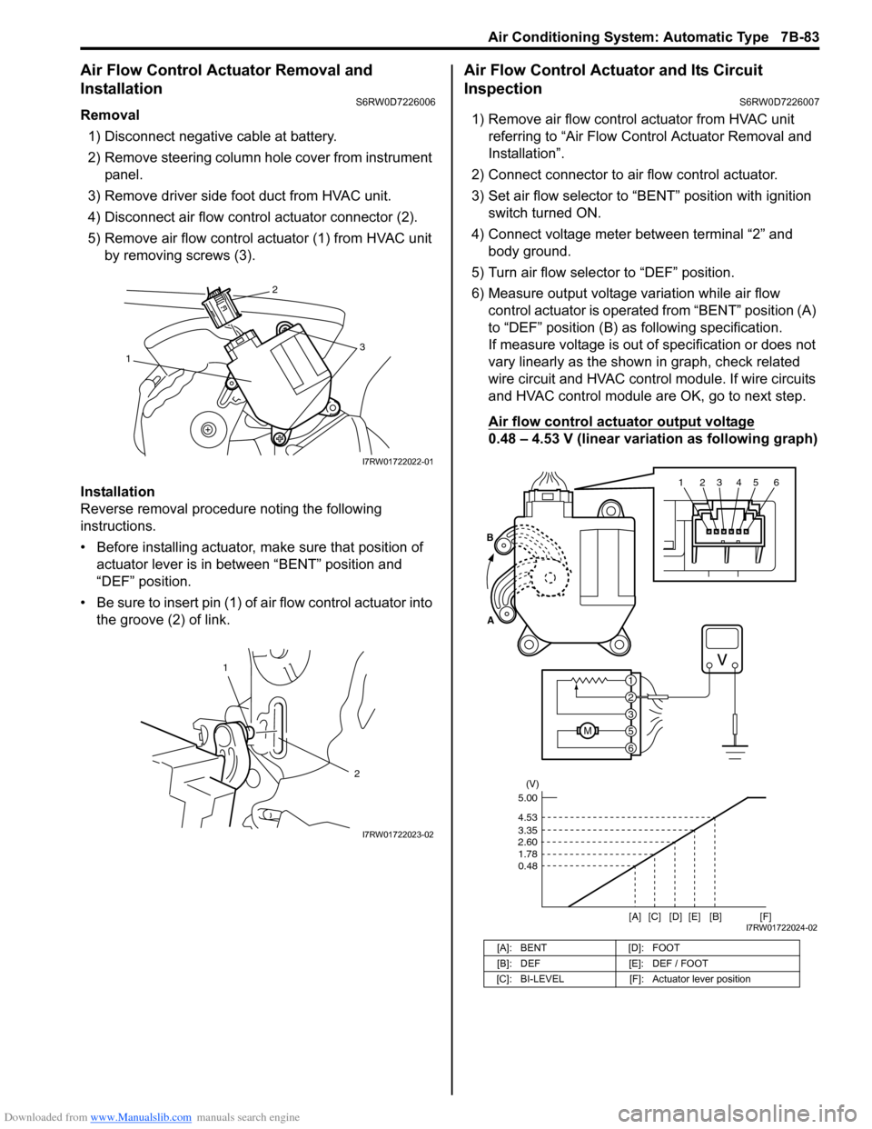
4) Disconnect air flow control actuator connector (2).
5) Remove air flow control actuator (1) from HVAC unit
by removing screws (3).
Installation
Reverse removal procedure noting the following
instructions.
• Before installing actuator, make sure that position of
actuator lever is in between “BENT” position and
“DEF” position.
• Be sure to insert pin (1) of air flow control actuator into
the groove (2) of link.
Air Flow Control Actuator and Its Circuit
Inspection
S6RW0D7226007
1) Remove air flow control actuator from HVAC unit
referring to “Air Flow Control Actuator Removal and
Installation”.
2) Connect connector to air flow control actuator.
3) Set air flow selector to “BENT” position with ignition
switch turned ON.
4) Connect voltage meter between terminal “2” and
body ground.
5) Turn air flow selector to “DEF” position.
6) Measure output voltage variation while air flow
control actuator is operated from “BENT” position (A)
to “DEF” position (B) as following specification.
If measure voltage is out of specification or does not
vary linearly as the shown in graph, check related
wire circuit and HVAC control module. If wire circuits
and HVAC control module are OK, go to next step.
Air flow control actuator output voltage
0.48 – 4.53 V (linear variation as following graph)
13
2
I7RW01722022-01
1
2
I7RW01722023-02
[A]: BENT [D]: FOOT
[B]: DEF [E]: DEF / FOOT
[C]: BI-LEVEL [F]: Actuator lever position
123456
6
M5
3
2
1 A
B
(V)
4.53
3.35
2.60
1.78
0.48
[A][B]
[C] [D] [E][F]5.00
I7RW01722024-02
Page 1024 of 1556
Downloaded from www.Manualslib.com manuals search engine 7B-84 Air Conditioning System: Automatic Type
7) Set air flow selector of HVAC control module to
“DEF” position with ignition switch turned ON, and
make sure if the position of actuator lever is “DEF”
position (A).
8) Turn ignition switch to OFF position, and then
disconnect connector from air flow control actuator.
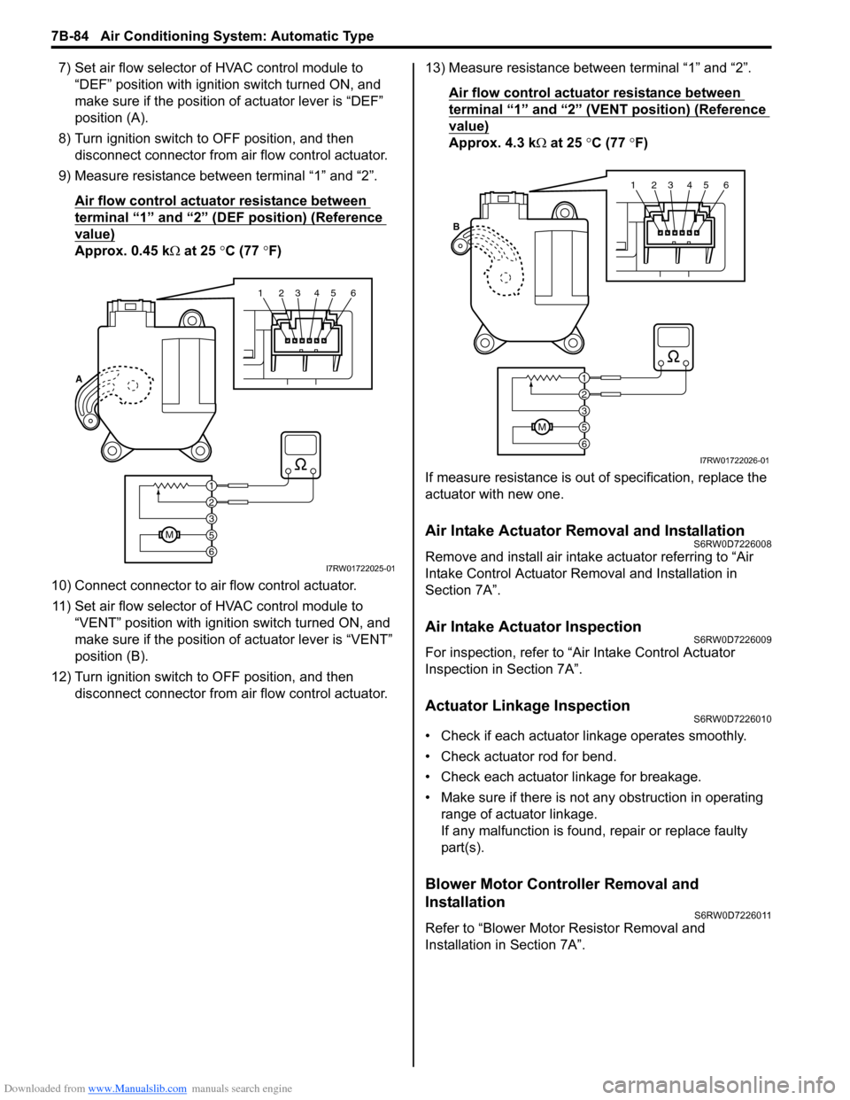
9) Measure resistance between terminal “1” and “2”.
Air flow control actuator resistance between
terminal “1” and “2” (DEF position) (Reference
value)
Approx. 0.45 kΩ at 25 °C (77 °F)
10) Connect connector to air flow control actuator.
11) Set air flow selector of HVAC control module to
“VENT” position with ignition switch turned ON, and
make sure if the position of actuator lever is “VENT”
position (B).
12) Turn ignition switch to OFF position, and then
disconnect connector from air flow control actuator.13) Measure resistance between terminal “1” and “2”.
Air flow control actuator resistance between
terminal “1” and “2” (VENT position) (Reference
value)
Approx. 4.3 kΩ at 25 °C (77 °F)
If measure resistance is out of specification, replace the
actuator with new one.
Air Intake Actuator Removal and InstallationS6RW0D7226008
Remove and install air intake actuator referring to “Air
Intake Control Actuator Removal and Installation in
Section 7A”.
Air Intake Actuator InspectionS6RW0D7226009
For inspection, refer to “Air Intake Control Actuator
Inspection in Section 7A”.
Actuator Linkage InspectionS6RW0D7226010
• Check if each actuator linkage operates smoothly.
• Check actuator rod for bend.
• Check each actuator linkage for breakage.
• Make sure if there is not any obstruction in operating
range of actuator linkage.
If any malfunction is found, repair or replace faulty
part(s).
Blower Motor Controller Removal and
Installation
S6RW0D7226011
Refer to “Blower Motor Resistor Removal and
Installation in Section 7A”.
123456
6
M5
3
2
1 A
I7RW01722025-01
123456
6
M5
3
2
1 B
I7RW01722026-01
Page 1034 of 1556
Downloaded from www.Manualslib.com manuals search engine 8A-3 Seat Belts:
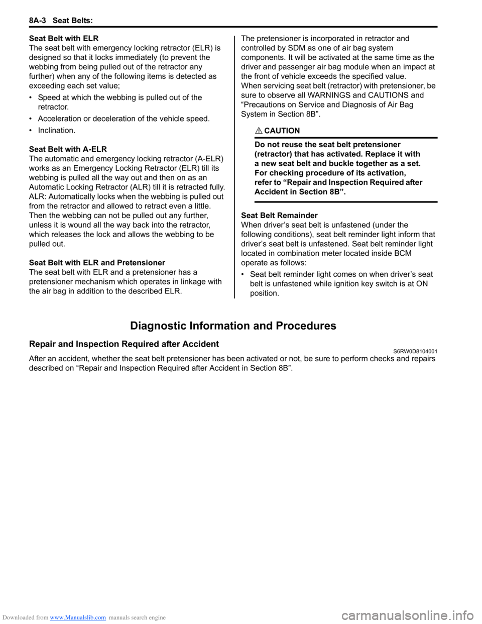
Seat Belt with ELR
The seat belt with emergency locking retractor (ELR) is
designed so that it locks immediately (to prevent the
webbing from being pulled out of the retractor any
further) when any of the following items is detected as
exceeding each set value;
• Speed at which the webbing is pulled out of the
retractor.
• Acceleration or deceleration of the vehicle speed.
• Inclination.
Seat Belt with A-ELR
The automatic and emergency locking retractor (A-ELR)
works as an Emergency Locking Retractor (ELR) till its
webbing is pulled all the way out and then on as an
Automatic Locking Retractor (ALR) till it is retracted fully.
ALR: Automatically locks when the webbing is pulled out
from the retractor and allowed to retract even a little.
Then the webbing can not be pulled out any further,
unless it is wound all the way back into the retractor,
which releases the lock and allows the webbing to be
pulled out.
Seat Belt with ELR and Pretensioner
The seat belt with ELR and a pretensioner has a
pretensioner mechanism which operates in linkage with
the air bag in addition to the described ELR.The pretensioner is incorporated in retractor and
controlled by SDM as one of air bag system
components. It will be activated at the same time as the
driver and passenger air bag module when an impact at
the front of vehicle exceeds the specified value.
When servicing seat belt (retractor) with pretensioner, be
sure to observe all WARNINGS and CAUTIONS and
“Precautions on Service and Diagnosis of Air Bag
System in Section 8B”.
CAUTION!
Do not reuse the seat belt pretensioner
(retractor) that has activated. Replace it with
a new seat belt and buckle together as a set.
For checking procedure of its activation,
refer to “Repair and Inspection Required after
Accident in Section 8B”.
Seat Belt Remainder
When driver’s seat belt is unfastened (under the
following conditions), seat belt reminder light inform that
driver’s seat belt is unfastened. Seat belt reminder light
located in combination meter located inside BCM
operate as follows:
• Seat belt reminder light comes on when driver’s seat
belt is unfastened while ignition key switch is at ON
position.
Diagnostic Information and Procedures
Repair and Inspection Required after AccidentS6RW0D8104001
After an accident, whether the seat belt pretensioner has been activated or not, be sure to perform checks and repairs
described on “Repair and Inspection Required after Accident in Section 8B”.
Page 1048 of 1556
![SUZUKI SX4 2006 1.G Service Workshop Manual Downloaded from www.Manualslib.com manuals search engine 8B-9 Air Bag System:
Terminal arrangement of SDM (viewed from harness side)
[A]: Shorting bar 11. BCM 25. Driver seat belt pretensioner
[B]: C SUZUKI SX4 2006 1.G Service Workshop Manual Downloaded from www.Manualslib.com manuals search engine 8B-9 Air Bag System:
Terminal arrangement of SDM (viewed from harness side)
[A]: Shorting bar 11. BCM 25. Driver seat belt pretensioner
[B]: C](/manual-img/20/7612/w960_7612-1047.png)
Downloaded from www.Manualslib.com manuals search engine 8B-9 Air Bag System:
Terminal arrangement of SDM (viewed from harness side)
[A]: Shorting bar 11. BCM 25. Driver seat belt pretensioner
[B]: Connector 12. Combination meter 26. Passenger seat belt pretensioner
[C]: Junction block with BCM model 13. “AIR BAG” warning light27. Driver side-air bag (inflator) module (8-channel system)
[D]: Junction block without BCM model 14. Light driver 28. Passenger side-air bag (inflator) module (8-channel system)
1. Battery 15. SDM 29. Driver side curtain-air bag (inflator) module (8-channel
system)
2. Main fuse 16. To HVAC control module (auto A/C model) 30. Passenger side curtain-air bag (inflator) module (8-channel
system)
3. Fuse 17. Data link connector (DLC) 31. Safing power driver
4. Individual circuit fuse box No.1 18. Forward impact-sensor 32. X-Y-G (longitudinal / lateral acceleration)
5. “IGN” fuse 19. Driver side impact-sensor (8-channel
system)33. DC / DC converter
6. Ignition switch 20. Passenger side impact-sensor (8-channel
system)34. Mechanical longitudinal G sensor (switch)
7. Junction block assembly 21. Ground for air bag system 35. Back up capacitor
8. “DOME” fuse 22. Contact coil assembly
9. “METER” fuse 23. Driver air bag (inflator) module
10. “A/B” fuse 24. Passenger air bag (inflator) module
1
2 3 4 5 6 7 8 9 10 11 12 13 14 15 16 17 18 19 20 21 22 23 24 25 26
27 28 29 30 31 32 33 34 35 36 37 38 39 40 41 42 43 44 45 46 47 48 49 50 51
1
I7RW01822003-02
1. SDM Connector “L04”
Page 1049 of 1556
Downloaded from www.Manualslib.com manuals search engine Air Bag System: 8B-10
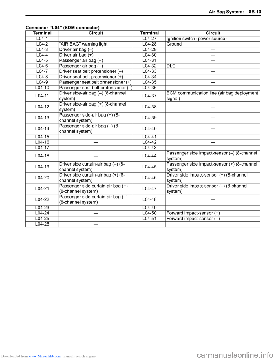
Connector “L04” (SDM connector)
Terminal Circuit Terminal Circuit
L04-1 — L04-27 Ignition switch (power source)
L04-2 “AIR BAG” warning light L04-28 Ground
L04-3 Driver air bag (–) L04-29 —
L04-4 Driver air bag (+) L04-30 —
L04-5 Passenger air bag (+) L04-31 —
L04-6 Passenger air bag (–) L04-32 DLC
L04-7 Driver seat belt pretensioner (–) L04-33 —
L04-8 Driver seat belt pretensioner (+) L04-34 —
L04-9 Passenger seat belt pretensioner (+) L04-35 —
L04-10 Passenger seat belt pretensioner (–) L04-36 —
L04-11 Driver side-air bag (–) (8-channel
system)L04-37 BCM communication line (air bag deployment
signal)
L04-12 Driver side-air bag (+) (8-channel
system)L04-38 —
L04-13 Passenger side-air bag (+) (8-
channel system)L04-39 —
L04-14 Passenger side-air bag (–) (8-
channel system)L04-40 —
L04-15 — L04-41 —
L04-16 — L04-42 —
L04-17 — L04-43 —
L04-18 — L04-44 Passenger side impact-sensor (–) (8-channel
system)
L04-19 Driver side curtain-air bag (–) (8-
channel system)L04-45 Passenger side impact-sensor (+) (8-channel
system)
L04-20 Driver side curtain-air bag (+) (8-
channel system)L04-46 Driver side impact-sensor (+) (8-channel
system)
L04-21 Passenger side curtain-air bag (+)
(8-channel system)L04-47 Driver side impact-sensor (–) (8-channel
system)
L04-22 Passenger side curtain-air bag (–)
(8-channel system)L04-48 —
L04-23 — L04-49 —
L04-24 — L04-50 Forward impact-sensor (+)
L04-25 — L04-51 Forward impact-sensor (–)
L04-26 —
Page 1052 of 1556
Downloaded from www.Manualslib.com manuals search engine 8B-13 Air Bag System:
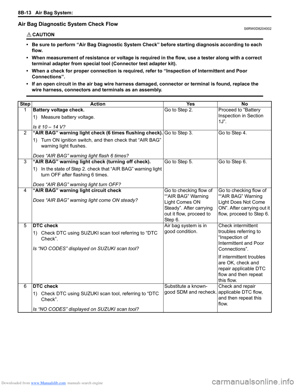
Air Bag Diagnostic System Check FlowS6RW0D8204002
CAUTION!
• Be sure to perform “Air Bag Diagnostic System Check” before starting diagnosis according to each
flow.
• When measurement of resistance or voltage is required in the flow, use a tester along with a correct
terminal adapter from special tool (Connector test adapter kit).
• When a check for proper connection is required, refer to “Inspection of Intermittent and Poor
Connections”.
• If an open circuit in the air bag wire harness damaged, connector or terminal is found, replace the
wire harness, connectors and terminals as an assembly.
Step Action Yes No
1Battery voltage check.
1) Measure battery voltage.
Is it 10 – 14 V?Go to Step 2. Proceed to “Battery
Inspection in Section
1J”.
2“AIR BAG” warning light check (6 times flushing check).
1) Turn ON ignition switch, and then check that “AIR BAG”
warning light flushes.
Does “AIR BAG” warning light flash 6 times?Go to Step 3. Go to Step 4.
3“AIR BAG” warning light check (turning off check).
1) In the state of Step 2. check that “AIR BAG” warning light
turn OFF after flashing 6 times.
Does “AIR BAG” warning light turn OFF?Go to Step 5. Go to Step 6.
4“AIR BAG” warning light circuit check
Does “AIR BAG” warning light come ON steady?Go to checking flow of
““AIR BAG” Warning
Light Comes ON
Steady”. After carrying
out it flow, proceed to
St ep 6 .Go to checking flow of
““AIR BAG” Warning
Light Does Not Come
ON”. After carrying out it
flow, proceed to Step 6.
5DTC check
1) Check DTC using SUZUKI scan tool referring to “DTC
Check”.
Is “NO CODES” displayed on SUZUKI scan tool?Air bag system is in
good condition.Check intermittent
troubles referring to
“Inspection of
Intermittent and Poor
Connections”.
If intermittent troubles
are OK, check and
repair applicable DTC
flow and then repeat
this flow.
6DTC check
1) Check DTC using SUZUKI scan tool, referring to “DTC
Check”.
Is “NO CODES” displayed on SUZUKI scan tool?Substitute a known-
good SDM and recheck.Check and repair
applicable DTC flow,
and then repeat this
flow.