2006 SUZUKI SX4 tire pressure
[x] Cancel search: tire pressurePage 868 of 1556

Downloaded from www.Manualslib.com manuals search engine 6A-1 Steering General Diagnosis:
Ste eri ng
Steering General Diagnosis
Precautions
Precautions for Steering DiagnosisS6RW0D6100001
Since the problems in steering involve several systems, they must all be considered when diagnosing a complaint. To
avoid using the wrong symptom, always road test the vehicle first. Proceed with the following preliminary inspection
and correct any defects which are found.
1) Inspect tires for proper pressure and uneven wear.
2) Raise vehicle on a hoist and inspect steering system for loose or damaged parts.
3) Spin front wheels. Inspect for out-of-round tires, out-of-balance tires, bent rims, loosen and/or rough wheel
bearings.
Diagnostic Information and Procedures
Steering Symptom DiagnosisS6RW0D6104001
Condition Possible cause Correction / Reference Item
Hard steeringTire not adequately inflatedInflate tires to proper pressure.
Malfunction of power steering systemCheck and correct. Refer to “P/S System
Symptom Diagnosis in Section 6C”.
Bind in tie-rod end ball studs or lower
ball jointsReplace tie-rod end or front suspension control
arm.
Disturbed front wheel alignmentCheck and adjust front wheel alignment.
Bind in steering columnRepair or replace steering column assembly.
Rack and pinion adjustmentCheck and adjustment rack and pinion torque.
Too much play in steeringWheel bearings wornReplace wheel bearing.
Loose steering gear case boltsTighten gear case bolts.
Faulty steering gear case assemblyReplace steering gear case assembly.
Worn steering shaft jointsReplace steering lower shaft assembly.
Worn tie-rod ends or tie-rod inside ball
jointsReplace tie-rod end or tie-rod.
Worn lower ball jointsReplace front suspension control arm.
Rack and pinion adjustmentCheck and adjustment rack and pinion torque.
Poor return abilityBind in tie-rod end ball studsReplace tie-rod end.
Bind in ball jointsReplace front suspension control arm.
Bind in steering columnReplace steering column assembly.
Disturbed front end alignmentCheck and adjust front end alignment.
Faulty steering gear case assemblyReplace steering gear case assembly.
Tires not adequately inflatedAdjust tire pressure.
Rack and pinion adjustmentCheck and adjustment rack and pinion torque.
Rack and pinion noise
(Rattle or chuckle)Loose steering gear case boltsTighten steering gear case bolts.
Rack and pinion adjustmentCheck and adjustment rack and pinion torque.
Faulty steering gear case assemblyReplace steering gear case assembly.
Broken or otherwise damaged wheel
bearing(s)Replace wheel bearing(s).
Wander or poor steering
stabilityMismatched or uneven tiresReplace or inflate tires to proper pressure.
Loosen ball joints and tie-rod endsReplace suspension control arm or tie-rod end.
Faulty struts or mountingsReplace strut or repair mounting.
Loose stabilizer barTighten or replace stabilizer bar or bush.
Broken or sagging coil springsReplace coil spring.
Rack and pinion adjustmentCheck and adjustment rack and pinion torque.
Disturbed front wheel alignmentCheck and adjust front wheel alignment.
Faulty steering gear case assemblyReplace steering gear case assembly.
Page 869 of 1556

Downloaded from www.Manualslib.com manuals search engine Steering General Diagnosis: 6A-2
Steering System InspectionS6RW0D6104002
Check steering system referring to the following items.Erratic steering when
brakingWorn wheel bearingsReplace wheel bearing.
Broken or sagging coil springsReplace coil spring.
Wheel tires are inflated unequallyInflate tires to proper pressure.
Disturbed front wheel alignmentCheck and adjust front wheel alignment.
Brakes not working in unisonCheck and repair brake system.
Leaking wheel cylinder or caliperRepair or replace wheel cylinder or caliper.
Warped discsReplace brake disc.
Badly worn brake liningsReplace brake shoe lining.
Drum is out of round in some brakesReplace brake drum.
Defective wheel cylindersReplace or repair wheel cylinder. Condition Possible cause Correction / Reference Item
Inspection Item Referring section
Steering wheel Play, rattle “Steering Wheel Play Check in Section 6C”
Tie-rod end Looseness and damage “Tie-Rod End Inspection in Section 6C”
Wheel alignment “Front Wheel Alignment Inspection and Adjustment in
Section 2B”
Tie-rod end boot Damage “Tie-Rod End Boot On-Vehicle Inspection in Section 6C”
Steering rack boot Damage “Steering Rack Boot Inspection in Section 6C”
Steering shaft joint Rattle and damage “Steering Shaft Joint On-Vehicle Inspection in Section 6C”
EPS system Operation “EPS System Check in Section 6C”
Page 914 of 1556

Downloaded from www.Manualslib.com manuals search engine 6C-34 Power Assisted Steering System:
Steering Wheel Play CheckS6RW0D6304021
• Check steering wheel for looseness or rattle by
moving it in its shaft direction and lateral direction.
If found defective, repair or replace.
• Check steering wheel for play, holding vehicle in
straight forward condition on the ground with engine
stopped.
If steering wheel play is not within specification,
inspect as follows and replace if found defective.
– Tie-rod end ball stud for wear (Ball stud should
move when more than 0.2 N⋅m (2 kg-cm, 0.44 lb-ft)
torque is applied.)
– Lower ball joint for wear
– Steering shaft joint for wear
– Steering pinion or rack gear for wear or breakage
– Each part for looseness
Steering wheel play
“a”
: 0 – 30 mm (0 – 1.18 in.)
Steering Force CheckS6RW0D6304022
1) Place vehicle on level road and set steering wheel at
straight-ahead position.
2) Check if tire inflation pressure is as specified
referring to the tire placard.
3) Remove driver air bag (inflator) module referring to
“Driver Air Bag (Inflator) Module Removal and
Installation in Section 8B”.
4) Start engine.
5) With engine idling, measure steering force by turning
torque wrench.
Steering force
: Less than 6.4 N⋅m (0.64 kgf-m, 4.6 lb-ft)
6) Install driver air bag (inflator) module referring to
“Driver Air Bag (Inflator) Module Removal and
Installation in Section 8B”.
I3RM0A630021-01
I3RM0A630022-01
Page 1168 of 1556

Downloaded from www.Manualslib.com manuals search engine 9A-1 Wiring Systems:
Body, Cab and Accessories
Wiring Systems
Precautions
Cautions in Body Electrical System ServicingS6RW0D9100001
When servicing the electric systems, observe the cautions described in “Air Bag Warning in Section 00” to protect
electrical parts and to prevent a fire.
General Description
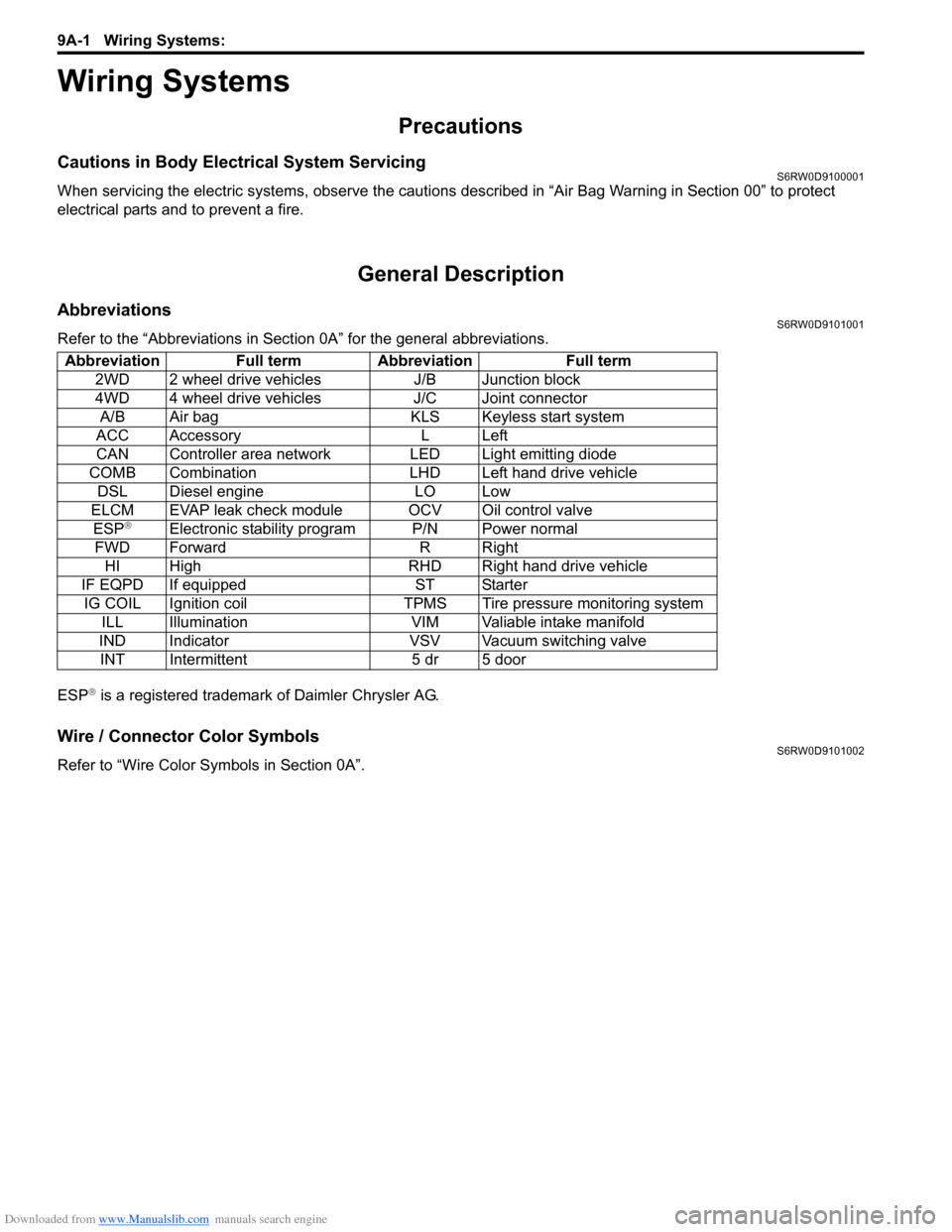
AbbreviationsS6RW0D9101001
Refer to the “Abbreviations in Section 0A” for the general abbreviations.
ESP
® is a registered trademark of Daimler Chrysler AG.
Wire / Connector Color SymbolsS6RW0D9101002
Refer to “Wire Color Symbols in Section 0A”. Abbreviation Full term Abbreviation Full term
2WD 2 wheel drive vehicles J/B Junction block
4WD 4 wheel drive vehicles J/C Joint connector
A/B Air bag KLS Keyless start system
ACC Accessory L Left
CAN Controller area network LED Light emitting diode
COMB Combination LHD Left hand drive vehicle
DSL Diesel engine LO Low
ELCM EVAP leak check module OCV Oil control valve
ESP
®Electronic stability program P/N Power normal
FWD Forward R Right
HI High RHD Right hand drive vehicle
IF EQPD If equipped ST Starter
IG COIL Ignition coil TPMS Tire pressure monitoring system
ILL Illumination VIM Valiable intake manifold
IND Indicator VSV Vacuum switching valve
INT Intermittent 5 dr 5 door
Page 1339 of 1556

Downloaded from www.Manualslib.com manuals search engine Lighting Systems: 9B-20
Igniter Removal and Installation (Discharge
Headlight Model)
S6RW0D9206024
WARNING!
Be sure to read “Precautions for Discharge
Headlight Service (If Equipped)” carefully
before working. Neglecting them may result
in personal injury.
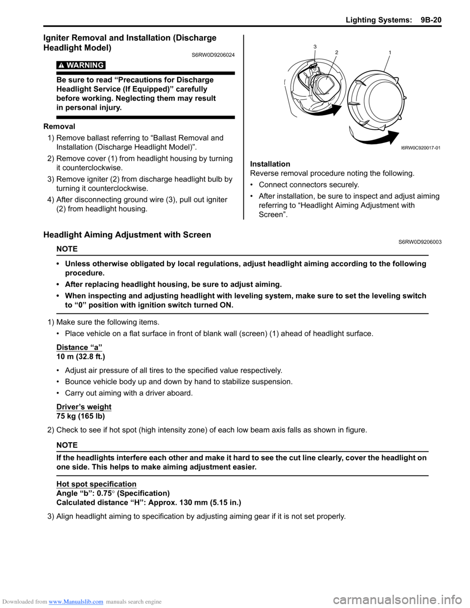
Removal
1) Remove ballast referring to “Ballast Removal and
Installation (Discharge Headlight Model)”.
2) Remove cover (1) from headlight housing by turning
it counterclockwise.
3) Remove igniter (2) from discharge headlight bulb by
turning it counterclockwise.
4) After disconnecting ground wire (3), pull out igniter
(2) from headlight housing.Installation
Reverse removal procedure noting the following.
• Connect connectors securely.
• After installation, be sure to inspect and adjust aiming
referring to “Headlight Aiming Adjustment with
Screen”.
Headlight Aiming Adjustment with ScreenS6RW0D9206003
NOTE
• Unless otherwise obligated by local regulations, adjust headlight aiming according to the following
procedure.
• After replacing headlight housing, be sure to adjust aiming.
• When inspecting and adjusting headlight with leveling system, make sure to set the leveling switch
to “0” position with ignition switch turned ON.
1) Make sure the following items.
• Place vehicle on a flat surface in front of blank wall (screen) (1) ahead of headlight surface.
Distance “a”
10 m (32.8 ft.)
• Adjust air pressure of all tires to the specified value respectively.
• Bounce vehicle body up and down by hand to stabilize suspension.
• Carry out aiming with a driver aboard.
Driver’s weight
75 kg (165 lb)
2) Check to see if hot spot (high intensity zone) of each low beam axis falls as shown in figure.
NOTE
If the headlights interfere each other and make it hard to see the cut line clearly, cover the headlight on
one side. This helps to make aiming adjustment easier.
Hot spot specification
Angle “b”: 0.75° (Specification)
Calculated distance “H”: Approx. 130 mm (5.15 in.)
3) Align headlight aiming to specification by adjusting aiming gear if it is not set properly.
2
1 3
I6RW0C920017-01
Page 1345 of 1556

Downloaded from www.Manualslib.com manuals search engine Lighting Systems: 9B-26
Front Fog Light Assembly Removal and
Installation (If Equipped)
S6RW0D9206014
WARNING!
• To avoid danger of being burned, don’t
touch when the bulb is hot.
• Don’t touch glass surface of bulb to avoid
deteriorate as the case may be unclear
when bulb light on at dirty condition.
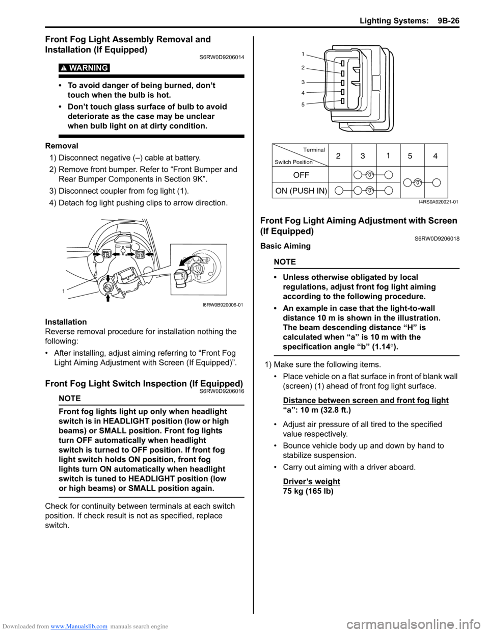
Removal
1) Disconnect negative (–) cable at battery.
2) Remove front bumper. Refer to “Front Bumper and
Rear Bumper Components in Section 9K”.
3) Disconnect coupler from fog light (1).
4) Detach fog light pushing clips to arrow direction.
Installation
Reverse removal procedure for installation nothing the
following:
• After installing, adjust aiming referring to “Front Fog
Light Aiming Adjustment with Screen (If Equipped)”.
Front Fog Light Switch Inspection (If Equipped)S6RW0D9206016
NOTE
Front fog lights light up only when headlight
switch is in HEADLIGHT position (low or high
beams) or SMALL position. Front fog lights
turn OFF automatically when headlight
switch is turned to OFF position. If front fog
light switch holds ON position, front fog
lights turn ON automatically when headlight
switch is tuned to HEADLIGHT position (low
or high beams) or SMALL position again.
Check for continuity between terminals at each switch
position. If check result is not as specified, replace
switch.
Front Fog Light Aiming Adjustment with Screen
(If Equipped)
S6RW0D9206018
Basic Aiming
NOTE
• Unless otherwise obligated by local
regulations, adjust front fog light aiming
according to the following procedure.
• An example in case that the light-to-wall
distance 10 m is shown in the illustration.
The beam descending distance “H” is
calculated when “a” is 10 m with the
specification angle “b” (1.14°).
1) Make sure the following items.
• Place vehicle on a flat surface in front of blank wall
(screen) (1) ahead of front fog light surface.
Distance between screen and front fog light
“a”: 10 m (32.8 ft.)
• Adjust air pressure of all tired to the specified
value respectively.
• Bounce vehicle body up and down by hand to
stabilize suspension.
• Carry out aiming with a driver aboard.
Driver’s weight
75 kg (165 lb)
1
I6RW0B920006-01
1
2
3
4
5
Switch PositionTerminal
ON (PUSH IN)231
54
OFF
I4RS0A920021-01
Page 1350 of 1556

Downloaded from www.Manualslib.com manuals search engine 9B-31 Lighting Systems:
Without initialization of the headlight auto leveling
system, it is not possible to obtain its proper function.
Also, if the headlight auto leveling system is not
initialized after replacing the headlight leveling control
module, the headlight leveling warning light in the
combination meter flashes.
1) Observe the following instructions.
• Park vehicle on level ground.
• Adjust air pressure of all tires to the specified
value respectively.
• Bounce vehicle body up and down by hand to
stabilize suspension.
2) Turn ignition switch to ON position.
3) Perform “Headlight Leveling Warning Light Check”.
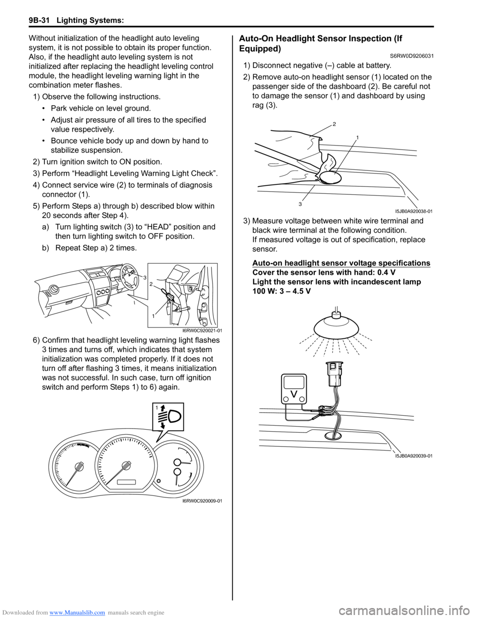
4) Connect service wire (2) to terminals of diagnosis
connector (1).
5) Perform Steps a) through b) described blow within
20 seconds after Step 4).
a) Turn lighting switch (3) to “HEAD” position and
then turn lighting switch to OFF position.
b) Repeat Step a) 2 times.
6) Confirm that headlight leveling warning light flashes
3 times and turns off, which indicates that system
initialization was completed properly. If it does not
turn off after flashing 3 times, it means initialization
was not successful. In such case, turn off ignition
switch and perform Steps 1) to 6) again.Auto-On Headlight Sensor Inspection (If
Equipped)
S6RW0D9206031
1) Disconnect negative (–) cable at battery.
2) Remove auto-on headlight sensor (1) located on the
passenger side of the dashboard (2). Be careful not
to damage the sensor (1) and dashboard by using
rag (3).
3) Measure voltage between white wire terminal and
black wire terminal at the following condition.
If measured voltage is out of specification, replace
sensor.
Auto-on headlight sensor voltage specifications
Cover the sensor lens with hand: 0.4 V
Light the sensor lens with incandescent lamp
100 W: 3 – 4.5 V3
1
2
I6RW0C920021-01
1
I6RW0C920009-01
2
1
3I5JB0A920038-01
I5JB0A920039-01