2006 SUZUKI SX4 oil replacement
[x] Cancel search: oil replacementPage 836 of 1556
Downloaded from www.Manualslib.com manuals search engine 5B-24 Manual Transmission/Transaxle:
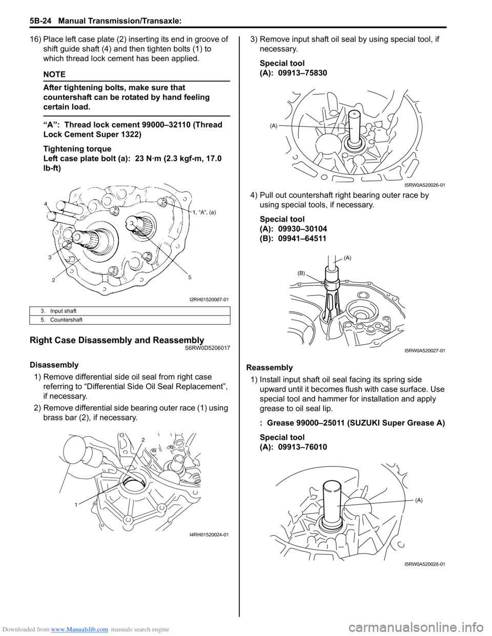
16) Place left case plate (2) inserting its end in groove of
shift guide shaft (4) and then tighten bolts (1) to
which thread lock cement has been applied.
NOTE
After tightening bolts, make sure that
countershaft can be rotated by hand feeling
certain load.
“A”: Thread lock cement 99000–32110 (Thread
Lock Cement Super 1322)
Tightening torque
Left case plate bolt (a): 23 N·m (2.3 kgf-m, 17.0
lb-ft)
Right Case Disassembly and ReassemblyS6RW0D5206017
Disassembly
1) Remove differential side oil seal from right case
referring to “Differential Side Oil Seal Replacement”,
if necessary.
2) Remove differential side bearing outer race (1) using
brass bar (2), if necessary.3) Remove input shaft oil seal by using special tool, if
necessary.
Special tool
(A): 09913–75830
4) Pull out countershaft right bearing outer race by
using special tools, if necessary.
Special tool
(A): 09930–30104
(B): 09941–64511
Reassembly
1) Install input shaft oil seal facing its spring side
upward until it becomes flush with case surface. Use
special tool and hammer for installation and apply
grease to oil seal lip.
: Grease 99000–25011 (SUZUKI Super Grease A)
Special tool
(A): 09913–76010
3. Input shaft
5. Countershaft
I2RH01520087-01
2
1
I4RH01520024-01
(A)
I5RW0A520026-01
(A)
(B)
I5RW0A520027-01
(A)
I5RW0A520028-01
Page 847 of 1556

Downloaded from www.Manualslib.com manuals search engine Manual Transmission/Transaxle: 5B-35
Gear Shift Shaft ComponentsS6RW0D5206022
5th and Reverse Gear Shift Shafts Disassembly
and Reassembly
S6RW0D5206023
Disassembly
Disassemble component parts by using special tool and
hammer.
Special tool
: 09922–85811
Reassembly
Replace or correct parts as required and assemble
shafts making sure that component parts are in proper
order as shown in figure.
NOTE
Install 2 steel balls (3) in reverse gear shift
arm (1) without fail.
Gear Shift Shaft and Fork InspectionS6RW0D5206024
1) Using feeler gauge, check clearance between fork
(1) and sleeve (2) and replace those parts if it
exceeds limit of 1.0 mm (0.039 in.).
NOTE
For correct judgement of parts replacement,
carefully inspect contact portion of fork and
sleeve.
Clearance “a” between fork and sleeve
Service limit: 1.0 mm (0.039 in.)
2) Insert each gear shift shaft into case and check that
it moves smoothly. If it doesn’t, correct by using
oilstone, reamer or the like.
I5RW0A520041-01
1. Low speed gear shift shaft 4. 5th & reverse gear shift guide shaft 7. 5th & reverse gear shift yoke
2. High speed gear shift shaft 5. Reverse gear shift arm : 13 N⋅m (1.3 kgf-m, 9.5 lb-ft)
3. 5th & reverse gear shift shaft 6. Gear shift locating bolt
: Apply sealant 99000-31260 to bolt thread.
2. Spring 6. 5th & reverse gear shift yoke
4. Spring pin 7. 5th & reverse gear shift guide shaft
5. 5th & reverse gear shift shaft
I5RW0A520042-01
I2RH01520068-01
Page 1051 of 1556
Downloaded from www.Manualslib.com manuals search engine Air Bag System: 8B-12
Diagnostic Information and Procedures
Air Bag Diagnostic System CheckS6RW0D8204001
WARNING!
To avoid deployment when troubleshooting
the air bag system, do not use electrical test
equipment such as a battery powered or AC
powered voltmeter, ohmmeter, etc., or any
type of electrical equipment other than that
specified in this manual. Do not use a non-
powered probe type tester.
Instructions in this manual must be followed
carefully, otherwise personal injury may
result.
CAUTION!
• The order in which DTCs are diagnosed is
very important. Failure to diagnose the
DTCs in the order specified may result in
extended diagnostic time, incorrect
diagnosis and incorrect parts replacement.
• When measurement of resistance or
voltage is required in the flow, use a tester
along with a correct terminal adapter from
special tool (Connector test adapter kit).
• When a check for proper connection is
required, refer to “Inspection of
Intermittent and Poor Connections”.
• If an open circuit in the air bag wire
harness damaged, connector or terminal is
found, replace the wire harness,
connectors and terminals as an assembly.
The diagnostic procedures used are designed to find
and repair air bag system malfunctions.
To get the best results, it is important to use the
diagnostic flow and follow the sequence in the following.
1) Perform the “Air Bag Diagnostic System Check
Flow”.
(The “Air Bag Diagnostic System Check Flow” must
be the starting point of any air bag system diagnosis.
The “Air Bag Diagnostic System Check Flow” checks
for proper “AIR BAG” warning light operation through
“AIR BAG” warning light and whether air bag DTCs
exist.)
2) Refer to the proper diagnostic flow as directed by the
“Air Bag Diagnostic System Check Flow”.
(The “Air Bag Diagnostic System Check Flow” will
lead you to the correct flow to diagnose any air bag
system malfunctions. Bypassing these procedures
may result in extended diagnostic time, incorrect
diagnosis and incorrect parts replacement.)
3) Repeat the “Air Bag Diagnostic System Check Flow”
after any repair or diagnostic procedures have been
performed.
(Performing the “Air Bag Diagnostic System Check
Flow” after all repair or diagnostic procedures will
ensure that the repair has been made correctly and
that no other malfunctions exist.)
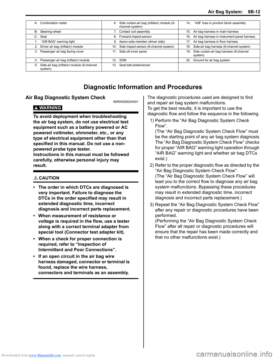
A: Combination meter 6. Side curtain-air bag (inflator) module (8-
channel system)14. “A/B” fuse in junction block assembly
B: Steering wheel 7. Contact coil assembly 15. Air bag harness in main harness
C: Seat 8. Forward impact-sensor 16. Air bag harness in instrument panel harness
1. “AIR BAG” warning light 9. Apron-side-member (driver side) 17. Air bag harness in floor harness
2. Driver air bag (inflator) module 10. Side impact-sensor (8-channel system) 18. Side-air bag harness (8-channel system)
3. Passenger air bag facing cover 11. Side sill inner panel 19. Side curtain-air bag harness (8-channel
system)
4. Passenger air bag (inflator) module 12. SDM 20. Ground for air bag system
5. Side-air bag (inflator) module (8-channel
system)13. Seat belt pretensioner
Page 1129 of 1556
Downloaded from www.Manualslib.com manuals search engine Air Bag System: 8B-90
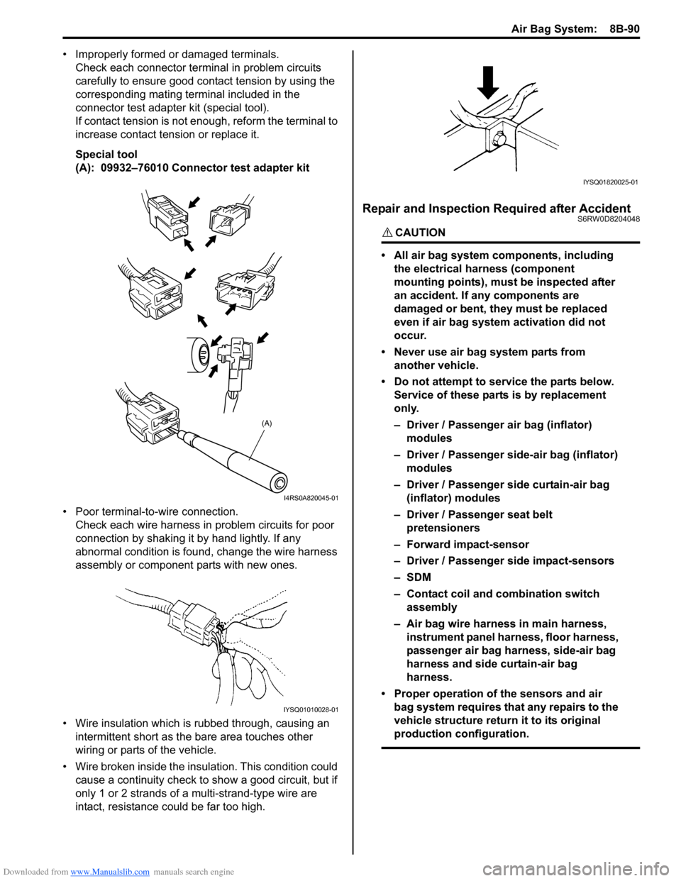
• Improperly formed or damaged terminals.
Check each connector terminal in problem circuits
carefully to ensure good contact tension by using the
corresponding mating terminal included in the
connector test adapter kit (special tool).
If contact tension is not enough, reform the terminal to
increase contact tension or replace it.
Special tool
(A): 09932–76010 Connector test adapter kit
• Poor terminal-to-wire connection.
Check each wire harness in problem circuits for poor
connection by shaking it by hand lightly. If any
abnormal condition is found, change the wire harness
assembly or component parts with new ones.
• Wire insulation which is rubbed through, causing an
intermittent short as the bare area touches other
wiring or parts of the vehicle.
• Wire broken inside the insulation. This condition could
cause a continuity check to show a good circuit, but if
only 1 or 2 strands of a multi-strand-type wire are
intact, resistance could be far too high.
Repair and Inspection Required after AccidentS6RW0D8204048
CAUTION!
• All air bag system components, including
the electrical harness (component
mounting points), must be inspected after
an accident. If any components are
damaged or bent, they must be replaced
even if air bag system activation did not
occur.
• Never use air bag system parts from
another vehicle.
• Do not attempt to service the parts below.
Service of these parts is by replacement
only.
– Driver / Passenger air bag (inflator)
modules
– Driver / Passenger side-air bag (inflator)
modules
– Driver / Passenger side curtain-air bag
(inflator) modules
– Driver / Passenger seat belt
pretensioners
– Forward impact-sensor
– Driver / Passenger side impact-sensors
–SDM
– Contact coil and combination switch
assembly
– Air bag wire harness in main harness,
instrument panel harness, floor harness,
passenger air bag harness, side-air bag
harness and side curtain-air bag
harness.
• Proper operation of the sensors and air
bag system requires that any repairs to the
vehicle structure return it to its original
production configuration.
(A)
I4RS0A820045-01
IYSQ01010028-01
IYSQ01820025-01
Page 1130 of 1556
Downloaded from www.Manualslib.com manuals search engine 8B-91 Air Bag System:
CAUTION!
After detecting one time of such collision as
to meet deployment conditions, the SDM
must not be used.
Refer to “Air Bag Diagnostic System Check”
when checking the SDM.
Accident with Deployment / Activation – Component
Replacement
When driver and passenger air bags are deployed, the
following components must be replaced.
• Driver and passenger air bag (inflator) modules
• Driver and passenger seat belt pretensioners
• SDM after detecting such collision as to meet
deployment conditions
• Forward impact-sensor
• Instrument panel
When side-air bag and side curtain-air bag are deployed,
the following components must be replaced.
• Deployed side-air bag (inflator) module
• Deployed side curtain-air bag (inflator) module
• Side impact-sensor
•SDM
Accident with or without Deployment / Activation –
Component Inspections
Certain air bag and restraint system components must
be inspected after any crash, whether the air bag system
activated or not. If any faulty condition is found in the
following checks, replace faulty part.
Those components are:
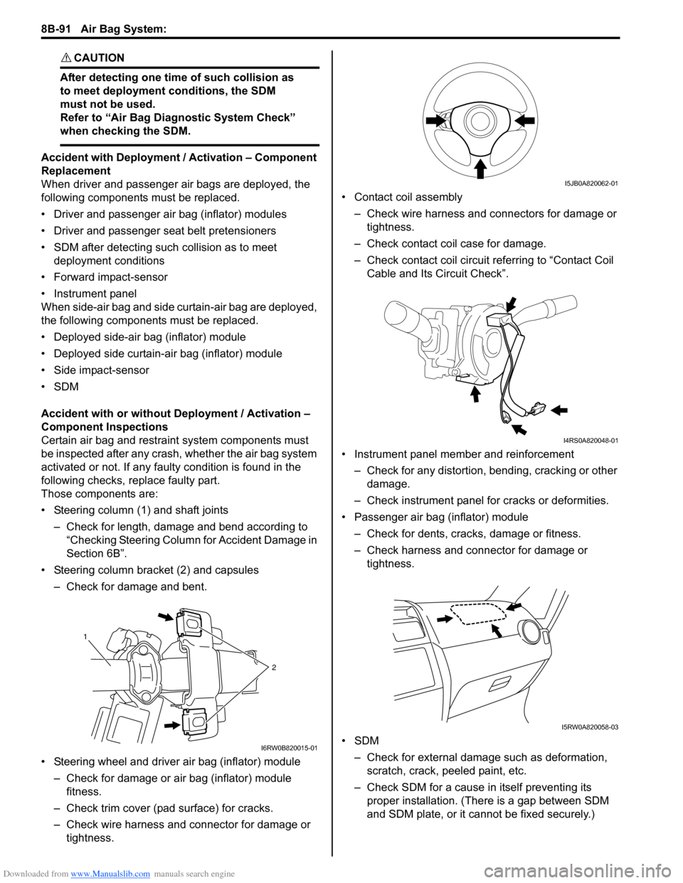
• Steering column (1) and shaft joints
– Check for length, damage and bend according to
“Checking Steering Column for Accident Damage in
Section 6B”.
• Steering column bracket (2) and capsules
– Check for damage and bent.
• Steering wheel and driver air bag (inflator) module
– Check for damage or air bag (inflator) module
fitness.
– Check trim cover (pad surface) for cracks.
– Check wire harness and connector for damage or
tightness.• Contact coil assembly
– Check wire harness and connectors for damage or
tightness.
– Check contact coil case for damage.
– Check contact coil circuit referring to “Contact Coil
Cable and Its Circuit Check”.
• Instrument panel member and reinforcement
– Check for any distortion, bending, cracking or other
damage.
– Check instrument panel for cracks or deformities.
• Passenger air bag (inflator) module
– Check for dents, cracks, damage or fitness.
– Check harness and connector for damage or
tightness.
•SDM
– Check for external damage such as deformation,
scratch, crack, peeled paint, etc.
– Check SDM for a cause in itself preventing its
proper installation. (There is a gap between SDM
and SDM plate, or it cannot be fixed securely.)
1
2
I6RW0B820015-01
I5JB0A820062-01
I4RS0A820048-01
I5RW0A820058-03
Page 1163 of 1556
Downloaded from www.Manualslib.com manuals search engine Table of Contents 9-iii
Headlight Bulb Replacement (Discharge
Headlight Model) ............................................. 9B-19
Ballast Removal and Installation (Discharge
Headlight Model) ............................................. 9B-19
Igniter Removal and Installation (Discharge
Headlight Model) ............................................. 9B-20
Headlight Aiming Adjustment with Screen ........ 9B-20
Headlight Switch (in Lighting Switch)
Removal and Installation................................. 9B-22
Headlight Switch (in Lighting Switch)
Inspection........................................................ 9B-22
Hazard Warning Switch Removal and
Installation ....................................................... 9B-23
Hazard Warning Switch Inspection ................... 9B-23
Brake Light Switch Inspection ........................... 9B-23
Turn Signal Light Switch (in Lighting Switch)
Removal and Installation................................. 9B-24
Turn Signal Light Switch (in Lighting Switch)
Inspection........................................................ 9B-24
Turn Signal and Hazard Warning Relay
Removal and Installation................................. 9B-24
Turn Signal and Hazard Warning Relay
Inspection........................................................ 9B-25
License Light Assembly Removal and
Installation ....................................................... 9B-25
Front Fog Light Assembly Removal and
Installation (If Equipped) ................................. 9B-26
Front Fog Light Switch Inspection (If
Equipped)........................................................ 9B-26
Front Fog Light Aiming Adjustment with
Screen (If Equipped) ....................................... 9B-26
Rear Fog Light Switch Inspection (If
Equipped)........................................................ 9B-27
Headlight Manual Levering Switch Inspection
(If Equipped) ................................................... 9B-28
Headlight Leveling Actuator Inspection (If
Equipped)........................................................ 9B-28
Height Sensor Removal and Installation (If
Equipped)........................................................ 9B-29
Height Sensor and Its Circuit Inspection (If
Equipped)........................................................ 9B-30
Headlight Leveling Control Module Removal
and Installation (If Equipped) .......................... 9B-30
Initialization of Headlight Auto Leveling
System ............................................................ 9B-30
Auto-On Headlight Sensor Inspection (If
Equipped)........................................................ 9B-31
Illumination Cancel Switch Inspection (If
Equipped)........................................................ 9B-32
Tail Light Relay, Headlight Relay, Front Fog
Light Relay Inspection (If Equipped) ............... 9B-32
Specifications..................................................... 9B-33
Tightening Torque Specifications ...................... 9B-33
Instrumentation / Driver Info. / Horn ...... 9C-1
Precautions........................................................... 9C-1
Precautions in Diagnosing Troubles for
Combination Meter............................................ 9C-1
General Description ............................................. 9C-1
CAN Communication System Description........... 9C-1Auto Volume Control System Description (If
Equipped) ..........................................................9C-3
Schematic and Routing Diagram ........................9C-4
Combination Meter Circuit Diagram ....................9C-4
Component Location ...........................................9C-5
Audio System Component Location ....................9C-5
Diagnostic Information and Procedures ............9C-6
Speedometer and VSS Symptom Diagnosis ......9C-6
Tachometer Symptom Diagnosis ........................9C-6
Engine Coolant Temperature (ECT) Meter
Symptom Diagnosis ..........................................9C-6
Fuel Meter Symptom Diagnosis ..........................9C-6
Low Fuel Warning Light Symptom Diagnosis .....9C-7
Oil Pressure Warning Light Symptom
Diagnosis ..........................................................9C-7
Brake and Parking Brake Warning Light
Symptom Diagnosis ..........................................9C-8
Seat Belt Reminder Light Symptom Diagnosis ....9C-8
A/T Shift Position Indicator Symptom
Diagnosis (A/T Model).......................................9C-8
Charge Warning Light Symptom Diagnosis ........9C-9
Main Beam (High Beam) Indicator Symptom
Diagnosis ..........................................................9C-9
Warning Buzzer Circuit Symptom Diagnosis ......9C-9
Cigarette Lighter Symptom Diagnosis (If
Equipped) ........................................................9C-10
Horn Symptom Diagnosis .................................9C-10
Information Display Symptom Diagnosis (If
Equipped) ........................................................9C-10
Clock System Diagnosis (If Equipped) ..............9C-11
Audio System Symptom Diagnosis (If
Equipped) ........................................................9C-12
Remote Audio Control Switch Symptom
Diagnosis (If Equipped) ...................................9C-13
Navigation Symptom Diagnosis (If Equipped)...9C-13
Repair Instructions ............................................9C-14
Ignition Switch Removal and Installation...........9C-14
Ignition Switch Inspection..................................9C-14
Combination Meter Removal and Installation ...9C-14
Fuel Level Sensor Removal and Installation .....9C-15
Fuel Level Sensor Inspection ............................9C-15
Oil Pressure Switch Removal and Installation ..9C-15
Oil Pressure Switch Inspection .........................9C-15
Engine Coolant Temperature (ECT) Sensor
Inspection ........................................................9C-16
Brake Fluid Level Switch Inspection .................9C-16
Parking Brake Switch Inspection.......................9C-16
Door Switch (Front / Rear Door) Inspection ......9C-16
Rear End Door Switch Inspection .....................9C-16
Outside Air Temperature Sensor Removal
and Installation (If Equipped) ..........................9C-17
Outside Air Temperature Sensor Inspection
(If Equipped)....................................................9C-17
Instrument Panel Removal and Installation.......9C-17
Information Display (Clock) Removal and
Installation .......................................................9C-18
Audio Unit Removal and Installation (If
Equipped) ........................................................9C-19
Page 1320 of 1556
Downloaded from www.Manualslib.com manuals search engine 9B-1 Lighting Systems:
Body, Cab and Accessories
Lighting Systems
Precautions
Precautions for Discharge Headlight Service (If Equipped)S6RW0D9200001
WARNING!
• Do not touch igniter or ballast when lighting switch is at “HEAD” position to avoid possible electric
shock.
• Do not measure voltage or resistance with tester connected to output connector of ballast or igniter
to avoid possible electric shock.
• Do not perform work where exposed to water including rain or with wet hands to avoid possible
electric shock.
• Disassembling igniter or ballast is strictly prohibited as it may cause an electric shock.
• Before inspecting or repairing discharge headlight or its peripheral parts, make sure that lighting
switch is at OFF position and battery is disconnected at negative terminal to avoid possible
electrical shock.
• Do not set lighting switch to “HEAD” position with connector disconnected or any part removed to
avoid possible electric shock.
• Do not touch glass surface of headlight bulb. Oil or grease attached on it may not only make bulb
service life shorter but also cause bulb to burst when lighting switch is turned on.
• Mercury, metal iodide and xenon gas are sealed in discharge headlight bulb. Be sure to dispose of
used discharge headlight bulb properly according to applicable rules or regulations.
Precautions in Diagnosing Troubles (Headlight Auto Leveling System)S6RW0D9200002
• Be sure to read “Air Bag Warning in Section 00” before inspection and observe what is written there.
• Replacement of height sensor and headlight leveling control module. When height sensor and/or headlight leveling
control module is replaced with new one, perform initialization of headlight auto leveling system according to
“Initialization of Headlight Auto Leveling System”.
General Description
Discharge Headlight Description (If Equipped)S6RW0D9201001
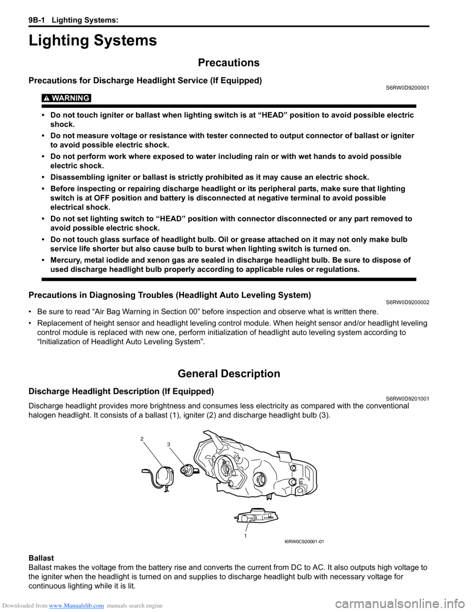
Discharge headlight provides more brightness and consumes less electricity as compared with the conventional
halogen headlight. It consists of a ballast (1), igniter (2) and discharge headlight bulb (3).
Ballast
Ballast makes the voltage from the battery rise and converts the current from DC to AC. It also outputs high voltage to
the igniter when the headlight is turned on and supplies to discharge headlight bulb with necessary voltage for
continuous lighting while it is lit.
2
1 3
I6RW0C920001-01