2006 SUZUKI SX4 checking oil
[x] Cancel search: checking oilPage 865 of 1556

Downloaded from www.Manualslib.com manuals search engine Table of Contents 6- i
6
Section 6
CONTENTS
Steering
Precautions ................................................. 6-1
Precautions............................................................. 6-1
Precautions on Steering........................................ 6-1
Steering General Diagnosis.................... 6A-1
Precautions........................................................... 6A-1
Precautions for Steering Diagnosis ..................... 6A-1
Diagnostic Information and Procedures ............ 6A-1
Steering Symptom Diagnosis .............................. 6A-1
Steering System Inspection ................................ 6A-2
Steering Wheel and Column................... 6B-1
Precautions........................................................... 6B-1
Service Precautions of Steering Wheel and
Column.............................................................. 6B-1
General Description ............................................. 6B-1
Steering Wheel and Column Construction .......... 6B-1
Diagnostic Information and Procedures ............ 6B-2
Checking Steering Column for Accident
Damage ............................................................ 6B-2
Repair Instructions .............................................. 6B-3
Steering Wheel and Column Construction .......... 6B-3
Steering Wheel Removal and Installation ........... 6B-4
Contact Coil Cable Assembly Removal and
Installation ......................................................... 6B-5
Centering Contact Coil Cable Assembly ............. 6B-6
Contact Coil Cable Assembly Inspection ............ 6B-6
Steering Column Removal and Installation ......... 6B-6
Steering Column Inspection ................................ 6B-8
Ignition Switch Cylinder Assembly Removal
and Installation (Non- Keyless Start Model)...... 6B-8
Steering Lock Assembly (Ignition Switch)
Removal and Installation................................... 6B-9
Steering Lower Shaft Removal and
Installation ....................................................... 6B-10
Specifications..................................................... 6B-11
Tightening Torque Specifications ...................... 6B-11
Special Tools and Equipment ........................... 6B-11
Special Tool ...................................................... 6B-11
Power Assisted Steering System........... 6C-1
Precautions........................................................... 6C-1
P/S System Note ................................................. 6C-1
Precautions in Diagnosing Troubles ................... 6C-1General Description .............................................6C-2
P/S System Description ......................................6C-2
EPS Diagnosis General Description ...................6C-3
On-Board Diagnostic System Description ...........6C-3
Schematic and Routing Diagram ........................6C-4
EPS System Wiring Circuit Diagram ...................6C-4
Diagnostic Information and Procedures ............6C-5
EPS System Check .............................................6C-5
“EPS” Warning Light Check ................................6C-8
DTC Check..........................................................6C-8
DTC Clearance ...................................................6C-9
DTC Table ...........................................................6C-9
Visual Inspection ...............................................6C-11
Scan Tool Data .................................................6C-12
P/S System Symptom Diagnosis ......................6C-13
DLC and Its Communication Check (No
communication to P/S Control Module)...........6C-14
“EPS” Warning Light Does Not Come ON with
Ignition Switch Turned ON before Engine
Starts ...............................................................6C-16
“EPS” Warning Light Remains ON Steady
after Engine Starts ..........................................6C-18
DTC C1111 / C1113 / C1115: Torque Sensor
Circuit Failure ..................................................6C-19
DTC C1116: Steering Torque Sensor Power
Supply Circuit ..................................................6C-21
DTC C1121 / C1123 / C1124: Vehicle Speed
Signal Circuit Failure .......................................6C-22
DTC C1122: Engine Speed Signal....................6C-24
DTC C1141 / C1142 / C1143 / C1145: Motor
Circuit Failure ..................................................6C-26
DTC C1153: P/S Control Module Power
Supply Circuit ..................................................6C-27
DTC C1155: P/S Control Module Internal
Failure .............................................................6C-28
P/S Control Module Power Supply and
Ground Circuit Check ......................................6C-29
Inspection of P/S Control Module and Its
Circuits ............................................................6C-30
Steering Wheel Play Check ..............................6C-34
Steering Force Check .......................................6C-34
Repair Instructions ............................................6C-35
Steering Gear Case Assembly Components ....6C-35
Tie-Rod End Boot On-Vehicle Inspection .........6C-36
Tie-Rod End Removal and Installation..............6C-36
Page 877 of 1556

Downloaded from www.Manualslib.com manuals search engine Steering Wheel and Column: 6B-8
3) Align flat part “a” of steering lower shaft (1) with bolt
hole “b” of shaft joint (2) of column as shown. Then
insert lower shaft into shaft joint of steering column.
4) Tighten lower shaft upper joint bolt (3) to specified
torque.
CAUTION!
After tightening column nuts, tighten steering
shaft upper joint bolt. Otherwise, shaft joint
bearing is damaged.
Tightening torque
Steering lower shaft assembly upper joint bolt
(a): 25 N·m (2.5 kgf-m, 18.5 lb-ft)
5) Install lighting switch and wiper switch to steering
column.
6) (Immobilizer model)
Install immobilizer control module from steering
column, referring to “ICM Removal and Installation in
Section 10C”.
7) Install contact coil cable assembly and steering
wheel referring to “Contact Coil Cable Assembly
Removal and Installation” and “Steering Wheel
Removal and Installation”.
8) Connect negative (–) cable to battery.
9) Enable air bag system referring to “Enabling Air Bag
System in Section 8B”.
Steering Column InspectionS6RW0D6206009
Check steering column for damage and operation
referring to “Checking Steering Column for Accident
Damage”.
Ignition Switch Cylinder Assembly Removal
and Installation (Non- Keyless Start Model)
S6RW0D6206010
Removal
1) Disconnect negative (–) cable at battery.
2) Disable air bag system referring to “Disabling Air
Bag System in Section 8B”.
3) Remove steering column upper and lower covers.
4) (Immobilizer model)
Remove immobilizer control module referring to
“ICM Removal and Installation in Section 10C”.
5) Remove ignition switch cylinder assembly as follows.
a) Turn ignition key to “ACC” position.
b) Insert 2 mm (0.078 in.) rod (2) through hole (3)
and push ignition switch cylinder lock.
c) Detach ignition switch cylinder assembly (1) from
steering lock assembly (4).
Installation
1) Install ignition switch cylinder assembly as follows.
a) Turn ignition key to “ACC” position.
b) In this state, push ignition switch cylinder
assembly into steering lock assembly till it clicks.
2) (Immobilizer model)
Install immobilizer control module referring to “ICM
Removal and Installation in Section 10C”.
3) Install upper and lower cover and screws.
4) Connect negative (–) cable to battery.
5) Enabling air bag system referring to “Enabling Air
Bag System in Section 8B”.
6) (Immobilizer model)
If ignition switch cylinder assembly (that is ignition
key) has replaced, register ignition key transponder
code to ECM referring to “Registration of the Ignition
Key in Section 10C”.
1 2
“a”“b”
3, (a)
I5RW0A620007-01
2
3
1
4
I5JB0A620025-01
Page 952 of 1556

Downloaded from www.Manualslib.com manuals search engine 7B-12 Air Conditioning System: Manual Type
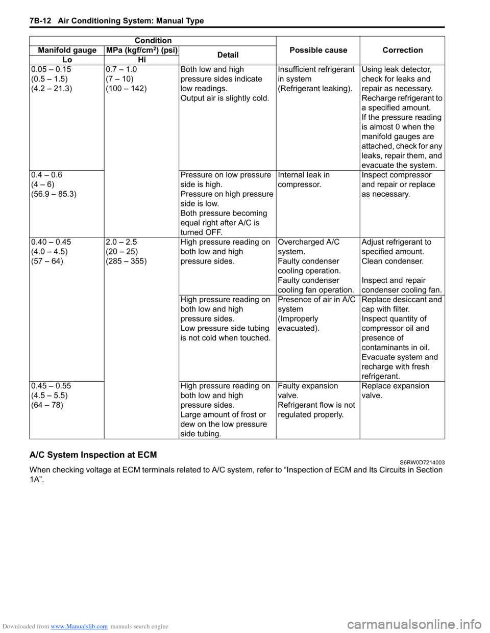
A/C System Inspection at ECMS6RW0D7214003
When checking voltage at ECM terminals related to A/C system, refer to “Inspection of ECM and Its Circuits in Section
1A”.0.05 – 0.15
(0.5 – 1.5)
(4.2 – 21.3)0.7 – 1.0
(7 – 10)
(100 – 142)Both low and high
pressure sides indicate
low readings.
Output air is slightly cold.Insufficient refrigerant
in system
(Refrigerant leaking).Using leak detector,
check for leaks and
repair as necessary.
Recharge refrigerant to
a specified amount.
If the pressure reading
is almost 0 when the
manifold gauges are
attached, check for any
leaks, repair them, and
evacuate the system.
0.4 – 0.6
(4 – 6)
(56.9 – 85.3)Pressure on low pressure
side is high.
Pressure on high pressure
side is low.
Both pressure becoming
equal right after A/C is
turned OFF.Internal leak in
compressor.Inspect compressor
and repair or replace
as necessary.
0.40 – 0.45
(4.0 – 4.5)
(57 – 64)2.0 – 2.5
(20 – 25)
(285 – 355)High pressure reading on
both low and high
pressure sides.Overcharged A/C
system.Adjust refrigerant to
specified amount.
Faulty condenser
cooling operation.Clean condenser.
Faulty condenser
cooling fan operation.Inspect and repair
condenser cooling fan.
High pressure reading on
both low and high
pressure sides.
Low pressure side tubing
is not cold when touched.Presence of air in A/C
system
(Improperly
evacuated).Replace desiccant and
cap with filter.
Inspect quantity of
compressor oil and
presence of
contaminants in oil.
Evacuate system and
recharge with fresh
refrigerant.
0.45 – 0.55
(4.5 – 5.5)
(64 – 78)High pressure reading on
both low and high
pressure sides.
Large amount of frost or
dew on the low pressure
side tubing.Faulty expansion
valve.
Refrigerant flow is not
regulated properly.Replace expansion
valve. Condition
Possible cause Correction Manifold gauge MPa (kgf/cm
2) (psi)
Detail
Lo Hi
Page 1130 of 1556

Downloaded from www.Manualslib.com manuals search engine 8B-91 Air Bag System:
CAUTION!
After detecting one time of such collision as
to meet deployment conditions, the SDM
must not be used.
Refer to “Air Bag Diagnostic System Check”
when checking the SDM.
Accident with Deployment / Activation – Component
Replacement
When driver and passenger air bags are deployed, the
following components must be replaced.
• Driver and passenger air bag (inflator) modules
• Driver and passenger seat belt pretensioners
• SDM after detecting such collision as to meet
deployment conditions
• Forward impact-sensor
• Instrument panel
When side-air bag and side curtain-air bag are deployed,
the following components must be replaced.
• Deployed side-air bag (inflator) module
• Deployed side curtain-air bag (inflator) module
• Side impact-sensor
•SDM
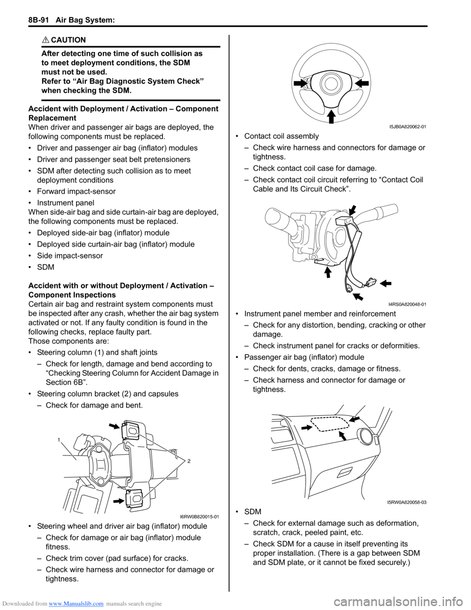
Accident with or without Deployment / Activation –
Component Inspections
Certain air bag and restraint system components must
be inspected after any crash, whether the air bag system
activated or not. If any faulty condition is found in the
following checks, replace faulty part.
Those components are:
• Steering column (1) and shaft joints
– Check for length, damage and bend according to
“Checking Steering Column for Accident Damage in
Section 6B”.
• Steering column bracket (2) and capsules
– Check for damage and bent.
• Steering wheel and driver air bag (inflator) module
– Check for damage or air bag (inflator) module
fitness.
– Check trim cover (pad surface) for cracks.
– Check wire harness and connector for damage or
tightness.• Contact coil assembly
– Check wire harness and connectors for damage or
tightness.
– Check contact coil case for damage.
– Check contact coil circuit referring to “Contact Coil
Cable and Its Circuit Check”.
• Instrument panel member and reinforcement
– Check for any distortion, bending, cracking or other
damage.
– Check instrument panel for cracks or deformities.
• Passenger air bag (inflator) module
– Check for dents, cracks, damage or fitness.
– Check harness and connector for damage or
tightness.
•SDM
– Check for external damage such as deformation,
scratch, crack, peeled paint, etc.
– Check SDM for a cause in itself preventing its
proper installation. (There is a gap between SDM
and SDM plate, or it cannot be fixed securely.)
1
2
I6RW0B820015-01
I5JB0A820062-01
I4RS0A820048-01
I5RW0A820058-03
Page 1332 of 1556

Downloaded from www.Manualslib.com manuals search engine 9B-13 Lighting Systems:
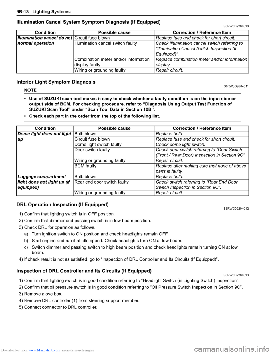
Illumination Cancel System Symptom Diagnosis (If Equipped)S6RW0D9204010
Interior Light Symptom DiagnosisS6RW0D9204011
NOTE
• Use of SUZUKI scan tool makes it easy to check whether a faulty condition is on the input side or
output side of BCM. For checking procedure, refer to “Diagnosis Using Output Test Function of
SUZUKI Scan Tool” under “Scan Tool Data in Section 10B”.
• Check each part in the order from the top of the following list.
DRL Operation Inspection (If Equipped)S6RW0D9204012
1) Confirm that lighting switch is in OFF position.
2) Confirm that dimmer and passing switch is in low beam position.
3) Check DRL for operation as follows.
a) Turn ignition switch to ON position and check headlights remain OFF.
b) Start engine and run it at idle speed. Check headlights turn ON at low beam.
c) Switch dimmer and passing switch to high beam position and check headlights remain turning ON at low
beam.
4) If check result is not as satisfied, go to “Inspection of DRL Controller and Its Circuits (If Equipped)”.
Inspection of DRL Controller and Its Circuits (If Equipped)S6RW0D9204013
1) Confirm that lighting switch is in good condition referring to “Headlight Switch (in Lighting Switch) Inspection”.
2) Confirm that oil pressure switch is in good condition referring to “Oil Pressure Switch Inspection in Section 9C”.
3) Remove glove box.
4) Remove DRL controller (1) from steering support member.
5) Connect connector to DRL controller.Condition Possible cause Correction / Reference Item
Illumination cancel do not
normal operationCircuit fuse blownReplace fuse and check for short circuit.
Illumination cancel switch faultyCheck illumination cancel switch referring to
“Illumination Cancel Switch Inspection (If
Equipped)”.
Combination meter and/or information
display faultyReplace combination meter and/or information
display.
Wiring or grounding faultyRepair circuit.
Condition Possible cause Correction / Reference Item
Dome light does not light
upBulb blownReplace bulb.
Circuit fuse blownReplace fuse and check for short circuit.
Dome light switch faultyCheck dome light switch.
Door switch faultyCheck door switch referring to “Door Switch
(Front / Rear Door) Inspection in Section 9C”.
Wiring or grounding faultyRepair circuit.
BCM faultyReplace after making sure that none of above
parts is faulty.
Luggage compartment
light does not light up (if
equipped)Bulb blownReplace bulb.
Rear end door switch faultyCheck switch referring to “Rear End Door
Switch Inspection in Section 9C”.
Wiring or grounding faultyRepair circuit.