2006 SUZUKI SX4 Starting motor relay
[x] Cancel search: Starting motor relayPage 280 of 1556

Downloaded from www.Manualslib.com manuals search engine 1C-12 Engine Electrical Devices:
Main Relay, Fuel Pump Relay, Starting Motor
Control Relay, Throttle Actuator Control Relay
and Radiator Cooling Fan Relay Inspection
S6RW0D1306017
1) Disconnect negative cable at battery.
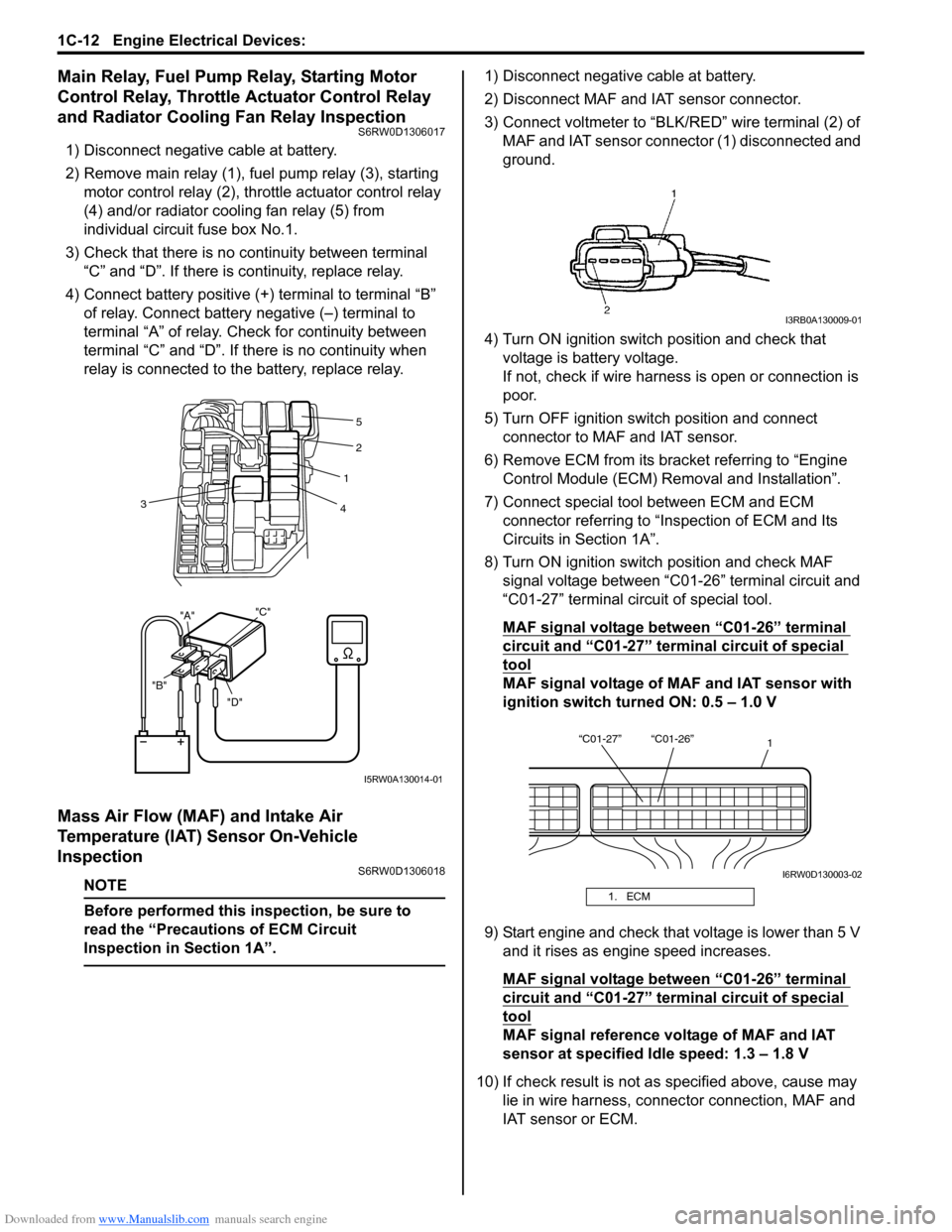
2) Remove main relay (1), fuel pump relay (3), starting
motor control relay (2), throttle actuator control relay
(4) and/or radiator cooling fan relay (5) from
individual circuit fuse box No.1.
3) Check that there is no continuity between terminal
“C” and “D”. If there is continuity, replace relay.
4) Connect battery positive (+) terminal to terminal “B”
of relay. Connect battery negative (–) terminal to
terminal “A” of relay. Check for continuity between
terminal “C” and “D”. If there is no continuity when
relay is connected to the battery, replace relay.
Mass Air Flow (MAF) and Intake Air
Temperature (IAT) Sensor On-Vehicle
Inspection
S6RW0D1306018
NOTE
Before performed this inspection, be sure to
read the “Precautions of ECM Circuit
Inspection in Section 1A”.
1) Disconnect negative cable at battery.
2) Disconnect MAF and IAT sensor connector.
3) Connect voltmeter to “BLK/RED” wire terminal (2) of
MAF and IAT sensor connector (1) disconnected and
ground.
4) Turn ON ignition switch position and check that
voltage is battery voltage.
If not, check if wire harness is open or connection is
poor.
5) Turn OFF ignition switch position and connect
connector to MAF and IAT sensor.
6) Remove ECM from its bracket referring to “Engine
Control Module (ECM) Removal and Installation”.
7) Connect special tool between ECM and ECM
connector referring to “Inspection of ECM and Its
Circuits in Section 1A”.
8) Turn ON ignition switch position and check MAF
signal voltage between “C01-26” terminal circuit and
“C01-27” terminal circuit of special tool.
MAF signal voltage between “C01-26” terminal
circuit and “C01-27” terminal circuit of special
tool
MAF signal voltage of MAF and IAT sensor with
ignition switch turned ON: 0.5 – 1.0 V
9) Start engine and check that voltage is lower than 5 V
and it rises as engine speed increases.
MAF signal voltage between “C01-26” terminal
circuit and “C01-27” terminal circuit of special
tool
MAF signal reference voltage of MAF and IAT
sensor at specified Idle speed: 1.3 – 1.8 V
10) If check result is not as specified above, cause may
lie in wire harness, connector connection, MAF and
IAT sensor or ECM.
"D" "B""A""C"
2
1
4 3
5
I5RW0A130014-01
1. ECM
I3RB0A130009-01
“C01-27” “C01-26”
1
I6RW0D130003-02
Page 406 of 1556

Downloaded from www.Manualslib.com manuals search engine 1I-1 Starting System:
Engine
Starting System
Schematic and Routing Diagram
Cranking System Circuit DiagramS6RW0D1902001
Diagnostic Information and Procedures
Cranking System Symptom DiagnosisS6RW0D1904001
Possible symptoms due to starting system trouble would be as follows:
• Starting motor does not run (or runs slowly)
• Starting motor runs but fails to crank engine
• Abnormal noise is heard
Proper diagnosis must be made to determine exactly where the cause of each trouble lies in battery, wiring harness,
(including starting motor switch), starting motor or engine.
Do not remove motor just because starting motor does not run. Check the following items and narrow down scope of
possible causes.
1) Condition of trouble
2) Tightness of battery terminals (including ground cable connection on engine side) and starting motor terminals
3) Discharge of battery
4) Mounting of starting motor
I4RS0A190001-01
1. Pinion drive lever 6. Magnetic switch contacts 11. Ignition & Starter switch
2. Pinion & Over-running clutch 7. Pull-in coil 12. Battery
3. Magnetic switch 8. Starting motor 13. To ECM
4. Hold-in coil 9. Starting motor control relay
5. Plunger 10. A/T: Transmission range sensor (shift switch)
Page 407 of 1556

Downloaded from www.Manualslib.com manuals search engine Starting System: 1I-2
Condition Possible cause Correction / Reference Item
Motor not running (No
operating sound of
magnetic switch)Transmission range sensor is not in P or
N, or not adjusted (A/T model)Shift in P or N, or adjust sensor. (A/T model)
Battery run downRecharge battery.
Battery voltage too low due to battery
deteriorationReplace battery.
Poor contact in battery terminal
connectionRetighten or replace.
Loose grounding cable connectionRetighten.
Fuse set loose or blown offTighten or replace.
Poor contacting action of ignition switch
and magnetic switchReplace.
Lead wire coupler loose in placeRetighten.
Open-circuit between ignition switch and
magnetic switchRepair.
Open-circuit in pull-in coilReplace magnetic switch.
Brushes are seating poorly or worn
downRepair or replace.
Poor sliding of plunger and/or pinionRepair.
Faulty starting motor control relay“Main Relay, Fuel Pump Relay, Starting Motor
Control Relay, Throttle Actuator Control Relay
and Radiator Cooling Fan Relay Inspection in
Section 1C”.
Faulty ECM and its circuit“Inspection of ECM and Its Circuits in Section
1A”.
Motor not running
(Operating sound of
magnetic switch heard)Battery run downRecharge battery.
Battery voltage too low due to battery
deteriorationReplace battery.
Loose battery cable connectionsRetighten.
Burnt main contact point, or poor
contacting action of magnetic switchReplace magnetic switch.
Brushes are seating poorly or worn
downRepair or replace.
Weakened brush springReplace.
Burnt commutatorReplace armature.
Layer short-circuit of armatureReplace.
Crankshaft rotation obstructedRepair.
Starting motor running
but too slow (small
torque) (If battery and
wiring are satisfactory,
inspect starting motor)Insufficient contact of magnetic switch
main contactsReplace magnetic switch.
Layer short-circuit of armatureReplace.
Disconnected, burnt or worn
commutatorRepair commutator or replace armature.
Worn brushesReplace brush.
Weakened brush springsReplace spring.
Burnt or abnormally worn end bushReplace bush.
Starting motor running,
but not cranking engineWorn pinion tipReplace over-running clutch.
Poor sliding of over-running clutchRepair.
Over-running clutch slippingReplace over-running clutch.
Worn teeth of ring gearReplace flywheel (M/T model) or drive plate (A/
T model).
NoiseAbnormally worn bushReplace bush.
Worn pinion or worn teeth of ring gearReplace over-running clutch, flywheel (M/T
model) or drive plate (A/T model).
Poor sliding of pinion (failure in return
movement)Repair or replace.
Worn internal or planetary gear teethReplace.
Lack of oil in each partLubricate.
Page 943 of 1556

Downloaded from www.Manualslib.com manuals search engine Air Conditioning System: Manual Type 7B-3
Manual A/C Electronic Input Output TableS6RW0D7211002
A/C Operation Description at ECMS6RW0D7211003
ECM controls the A/C compressor relay and condenser cooling fan relay according to signals from HVAC control unit,
A/C refrigerant pressure sensor, ECT sensor and evaporator temperature sensor. The A/C switch ON signal from
HVAC control unit is transmitted to ECM through BCM. For CAN communication system, refer to “CAN
Communication System Description in Section 1A”.
ECM turns ON the A/C compressor relay when the vehicle state satisfy conditions described below.
• A/C switch ON signal is inputted from HVAC control unit
• A/C refrigerant pressure is within specified range
• Evaporator temperature is within specified range
• Engine speed is within specified range
• Engine coolant temperature is lower than specified value
• Throttle opening is lower than specified value
• Vehicle is not in either state of starting or quick acceleration
• ECT sensor malfunction is not detected
• A/C refrigerant pressure sensor malfunction is not detected
Condenser Cooling Fan Relay Control
ECM turn ON the condenser cooling fan relay at the same time when ECM turn ON the A/C compressor relay.
ECM
BCM
A/C switch Air intake selector
A/C refrigerant pressure sensor
A/C evaporator temperature sensorCompressor relay
ECT sensor
Condensor cooling fan relay
*
Wheel speed sensor (VSS)
HVAC control unit
Blower motor Blower motor resistor
Air intake control actuator
*Blower speed selector
ABS control module
I6RW0C721001-01
*: CAN communication
Page 980 of 1556

Downloaded from www.Manualslib.com manuals search engine 7B-40 Air Conditioning System: Automatic Type
HVAC Control DescriptionS6RW0D7221002
Temperature Control
HVAC control module calculates the target temperature
control door position based on signals from the
temperature selector, inside air temperature sensor,
outside air temperature sensor and sunload sensor and
controls the temperature control actuator so that the
current position of the temperature control door matches
its target position.
Fan Speed Control
HVAC control module calculates the target blower fan
speed based on signals from the temperature selector,
inside air temperature sensor, outside air temperature
sensor, ECT sensor and sunload sensor, compares it
with the current blower fan speed inputted from the
blower motor controller to control the current blower fan
speed to the target level.
Air Flow Outlet Control
HVAC control module calculates the target temperature
control door position based on signals from the
temperature selector, inside air temperature sensor,
outside air temperature sensor, ECT sensor and sunload
sensor. Using thus obtained target temperature control
door position, it further calculates the target air flow
control door position and controls the air flow control
actuator so that the current air flow control door position
becomes the target position.
Air Intake Position Control
HVAC control module determines the position of the air
intake control door based on signals from the
temperature selector, inside air temperature sensor,
outside air temperature sensor and sunload sensor and
selects any of the following positions by controlling the
position of the air intake control door.
• FRESH position (FRE)
• RECIRCULATION position (REC)
• MIX position (MIX)A/C Compressor Relay Control
HVAC control module outputs A/C switch ON signal to
ECM via BCM when the vehicle state satisfy conditions
described below.
• A/C switch is ON
• Evaporator temperature is higher than specified value
• Evaporator temperature sensor malfunction is not
detected
Communication of ECM and BCM is established by CAN
(Controller Area Network). (For more detail of CAN
communication, refer to “CAN Communication System
Description in Section 1A”).
ECM turns ON the A/C compressor relay when the
vehicle state satisfy conditions described below.
• A/C switch ON signal is inputted
• A/C refrigerant pressure is within specified range
• Engine speed is within specified range
• Engine coolant temperature is lower than specified
value
• Throttle opening is lower than specified value
• Vehicle is not in either state of starting or quick
acceleration
• ECT sensor malfunction is not detected
• A/C refrigerant pressure sensor malfunction is not
detected
Condenser Cooling Fan Relay Control
ECM turn ON the condenser cooling fan relay at the
same time when ECM turn ON the A/C compressor
relay.
Sub-Cool A/C System DescriptionS6RW0D7221003
Refer to “Sub-Cool A/C System Description”.
Page 1184 of 1556

Downloaded from www.Manualslib.com manuals search engine 9A-17 Wiring Systems:
E: Main harness
No./Color Connective position No./Color Connective position
E01/GRY ECM E164/BLK Front fog light (L)
E08/BLK ABS control module E165/N Side turn signal light (R)
E33/N Wheel speed sensor (FR) E166/N Side turn signal light (L)
E35/BLU Wheel speed sensor (FL)E183/GRY Brake fluid level switch
E36/BLK A/C pressure sensor E221/BLK Main relay
E37/BLK Ambient temperature sensor E222/BLK Radiator fan relay #1
E40/YEL Forward sensor E223/BLK Radiator fan relay #2
E62/BLU Windshield washer motor E224/BLK Radiator fan relay #3
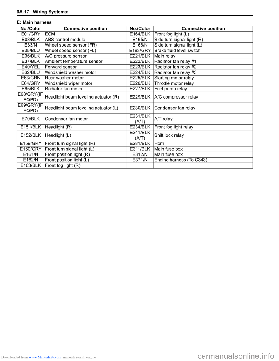
E63/GRN Rear washer motor E225/BLK Starting motor relay
E64/GRY Windshield wiper motor E226/BLK Throttle motor relay
E65/BLK Radiator fan motor E227/BLK Fuel pump relay
E68/GRY (IF
EQPD)Headlight beam leveling actuator (R) E229/BLK A/C compressor relay
E69/GRY (IF
EQPD)Headlight beam leveling actuator (L) E230/BLK Condenser fan relay
E70/BLK Condenser fan motorE231/BLK
(A/T)A/T relay
E151/BLK Headlight (R) E234/BLK Front fog light relay
E152/BLK Headlight (L)E241/BLK
(A/T)Shift lock relay
E159/GRY Front turn signal light (R) E281/BLK Horn
E160/GRY Front turn signal light (L) E311/BLK Main fuse box
E161/N Front position light (R) E312/N Main fuse box
E162/N Front position light (L) E371/N Engine harness (To C343)
E163/BLK Front fog light (R)
Page 1185 of 1556

Downloaded from www.Manualslib.com manuals search engine Wiring Systems: 9A-18
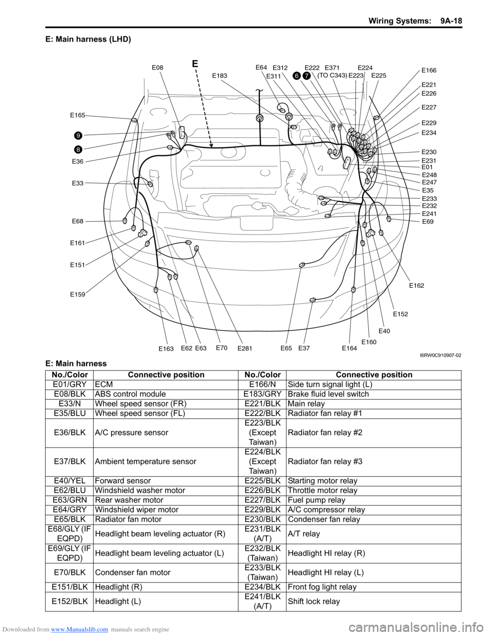
E: Main harness (LHD)
E: Main harness
E40
E33
E165
E36
E161
E68
E151
E159
E70E281E163E62E63E65E37E164
E64
E183
E08
E311
E312E222E224E225E223
E221
E371
(TO C343)E166
E227
E229
E234
E230
E01
E35
E69 E248
E247
E233
E232
E241
E162
E152
E160
E231
E226
8
9
76
E
I6RW0C910907-02
No./Color Connective position No./Color Connective position
E01/GRY ECM E166/N Side turn signal light (L)
E08/BLK ABS control module E183/GRY Brake fluid level switch
E33/N Wheel speed sensor (FR) E221/BLK Main relay
E35/BLU Wheel speed sensor (FL)E222/BLK Radiator fan relay #1
E36/BLK A/C pressure sensorE223/BLK
(Except
Ta i w a n )Radiator fan relay #2
E37/BLK Ambient temperature sensorE224/BLK
(Except
Ta i w a n )Radiator fan relay #3
E40/YEL Forward sensor E225/BLK Starting motor relay
E62/BLU Windshield washer motor E226/BLK Throttle motor relay
E63/GRN Rear washer motor E227/BLK Fuel pump relay
E64/GRY Windshield wiper motor E229/BLK A/C compressor relay
E65/BLK Radiator fan motor E230/BLK Condenser fan relay
E68/GLY (IF
EQPD)Headlight beam leveling actuator (R)E231/BLK
(A/T)A/T relay
E69/GLY (IF
EQPD)Headlight beam leveling actuator (L)E232/BLK
(Taiwan)Headlight HI relay (R)
E70/BLK Condenser fan motorE233/BLK
(Taiwan)Headlight HI relay (L)
E151/BLK Headlight (R) E234/BLK Front fog light relay
E152/BLK Headlight (L)E241/BLK
(A/T)Shift lock relay
Page 1201 of 1556

Downloaded from www.Manualslib.com manuals search engine Wiring Systems: 9A-34
Power Supply Diagram
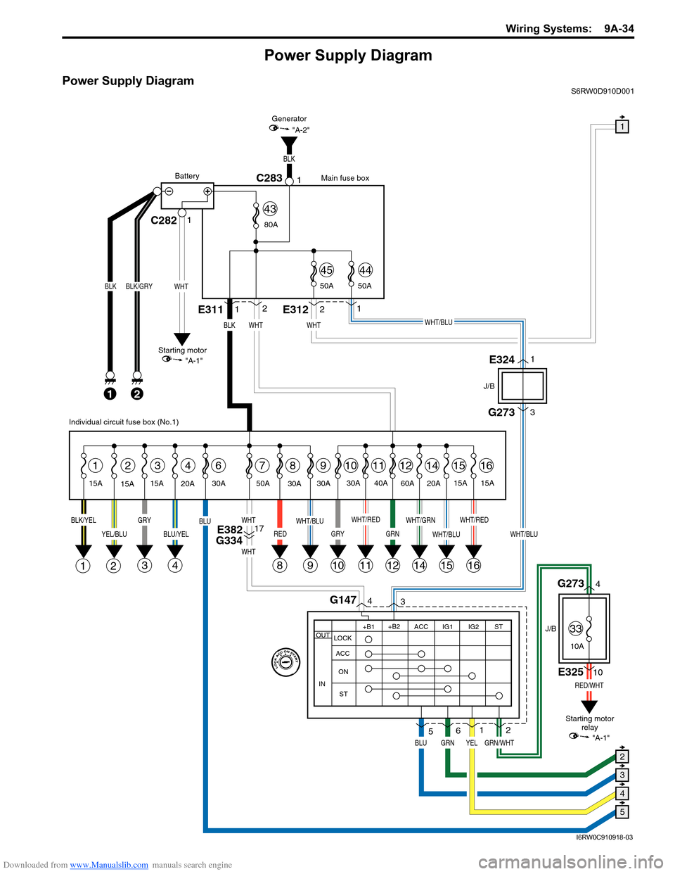
Power Supply DiagramS6RW0D910D001
G273
J/B
J/B
3
WHT/BLU
GRN/WHT
RED/WHT
4G1473
1
2
8
BLK
21
BLK/GRY
15A
15A15A
2314678
1E3112
WHT
1112141516
BLK/YELGRY
3
YEL/BLU
21
BLU/YEL
4
BLU
RED
WHT
WHT
WHT/RED
11
WHT/GRN
14
WHT/BLU
1516
WHT/RED
GRN
12
30A
9
WHT/BLU
9
30A
20A30A 50A40A
60A
20A15A
15A
BLK
2E3121
WHT/BLU
C282C28311
WHT
BLK
Main fuse box
Starting motor
"A-1"Generator
"A-2"
Battery
80A
50A 50A
4544
43
E3241
E32510
G2734
WHT
YEL
Individual circuit fuse box (No.1)
+B1
LOCK
ACC
ON
STACC IG1 IG2STOUT
IN
+B2
6
GRNBLU
5
Starting motor
relay
10
GRY
10
30A
E382
G33417
1
5
4
3
2
"A-1"
33
10A
I6RW0C910918-03