2006 SUZUKI SX4 Parking light
[x] Cancel search: Parking lightPage 1163 of 1556
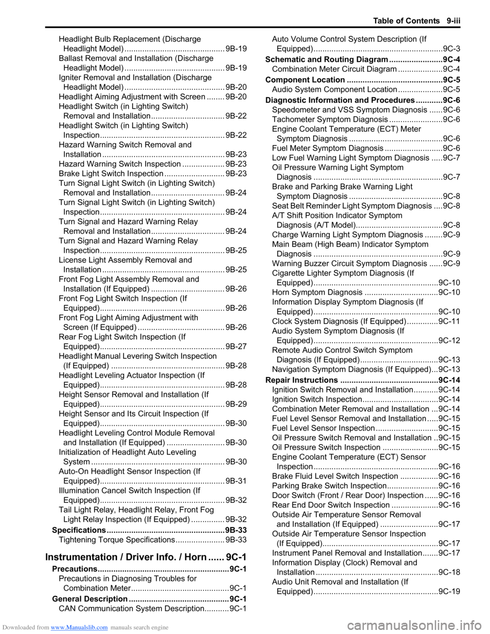
Downloaded from www.Manualslib.com manuals search engine Table of Contents 9-iii
Headlight Bulb Replacement (Discharge
Headlight Model) ............................................. 9B-19
Ballast Removal and Installation (Discharge
Headlight Model) ............................................. 9B-19
Igniter Removal and Installation (Discharge
Headlight Model) ............................................. 9B-20
Headlight Aiming Adjustment with Screen ........ 9B-20
Headlight Switch (in Lighting Switch)
Removal and Installation................................. 9B-22
Headlight Switch (in Lighting Switch)
Inspection........................................................ 9B-22
Hazard Warning Switch Removal and
Installation ....................................................... 9B-23
Hazard Warning Switch Inspection ................... 9B-23
Brake Light Switch Inspection ........................... 9B-23
Turn Signal Light Switch (in Lighting Switch)
Removal and Installation................................. 9B-24
Turn Signal Light Switch (in Lighting Switch)
Inspection........................................................ 9B-24
Turn Signal and Hazard Warning Relay
Removal and Installation................................. 9B-24
Turn Signal and Hazard Warning Relay
Inspection........................................................ 9B-25
License Light Assembly Removal and
Installation ....................................................... 9B-25
Front Fog Light Assembly Removal and
Installation (If Equipped) ................................. 9B-26
Front Fog Light Switch Inspection (If
Equipped)........................................................ 9B-26
Front Fog Light Aiming Adjustment with
Screen (If Equipped) ....................................... 9B-26
Rear Fog Light Switch Inspection (If
Equipped)........................................................ 9B-27
Headlight Manual Levering Switch Inspection
(If Equipped) ................................................... 9B-28
Headlight Leveling Actuator Inspection (If
Equipped)........................................................ 9B-28
Height Sensor Removal and Installation (If
Equipped)........................................................ 9B-29
Height Sensor and Its Circuit Inspection (If
Equipped)........................................................ 9B-30
Headlight Leveling Control Module Removal
and Installation (If Equipped) .......................... 9B-30
Initialization of Headlight Auto Leveling
System ............................................................ 9B-30
Auto-On Headlight Sensor Inspection (If
Equipped)........................................................ 9B-31
Illumination Cancel Switch Inspection (If
Equipped)........................................................ 9B-32
Tail Light Relay, Headlight Relay, Front Fog
Light Relay Inspection (If Equipped) ............... 9B-32
Specifications..................................................... 9B-33
Tightening Torque Specifications ...................... 9B-33
Instrumentation / Driver Info. / Horn ...... 9C-1
Precautions........................................................... 9C-1
Precautions in Diagnosing Troubles for
Combination Meter............................................ 9C-1
General Description ............................................. 9C-1
CAN Communication System Description........... 9C-1Auto Volume Control System Description (If
Equipped) ..........................................................9C-3
Schematic and Routing Diagram ........................9C-4
Combination Meter Circuit Diagram ....................9C-4
Component Location ...........................................9C-5
Audio System Component Location ....................9C-5
Diagnostic Information and Procedures ............9C-6
Speedometer and VSS Symptom Diagnosis ......9C-6
Tachometer Symptom Diagnosis ........................9C-6
Engine Coolant Temperature (ECT) Meter
Symptom Diagnosis ..........................................9C-6
Fuel Meter Symptom Diagnosis ..........................9C-6
Low Fuel Warning Light Symptom Diagnosis .....9C-7
Oil Pressure Warning Light Symptom
Diagnosis ..........................................................9C-7
Brake and Parking Brake Warning Light
Symptom Diagnosis ..........................................9C-8
Seat Belt Reminder Light Symptom Diagnosis ....9C-8
A/T Shift Position Indicator Symptom
Diagnosis (A/T Model).......................................9C-8
Charge Warning Light Symptom Diagnosis ........9C-9
Main Beam (High Beam) Indicator Symptom
Diagnosis ..........................................................9C-9
Warning Buzzer Circuit Symptom Diagnosis ......9C-9
Cigarette Lighter Symptom Diagnosis (If
Equipped) ........................................................9C-10
Horn Symptom Diagnosis .................................9C-10
Information Display Symptom Diagnosis (If
Equipped) ........................................................9C-10
Clock System Diagnosis (If Equipped) ..............9C-11
Audio System Symptom Diagnosis (If
Equipped) ........................................................9C-12
Remote Audio Control Switch Symptom
Diagnosis (If Equipped) ...................................9C-13
Navigation Symptom Diagnosis (If Equipped)...9C-13
Repair Instructions ............................................9C-14
Ignition Switch Removal and Installation...........9C-14
Ignition Switch Inspection..................................9C-14
Combination Meter Removal and Installation ...9C-14
Fuel Level Sensor Removal and Installation .....9C-15
Fuel Level Sensor Inspection ............................9C-15
Oil Pressure Switch Removal and Installation ..9C-15
Oil Pressure Switch Inspection .........................9C-15
Engine Coolant Temperature (ECT) Sensor
Inspection ........................................................9C-16
Brake Fluid Level Switch Inspection .................9C-16
Parking Brake Switch Inspection.......................9C-16
Door Switch (Front / Rear Door) Inspection ......9C-16
Rear End Door Switch Inspection .....................9C-16
Outside Air Temperature Sensor Removal
and Installation (If Equipped) ..........................9C-17
Outside Air Temperature Sensor Inspection
(If Equipped)....................................................9C-17
Instrument Panel Removal and Installation.......9C-17
Information Display (Clock) Removal and
Installation .......................................................9C-18
Audio Unit Removal and Installation (If
Equipped) ........................................................9C-19
Page 1196 of 1556
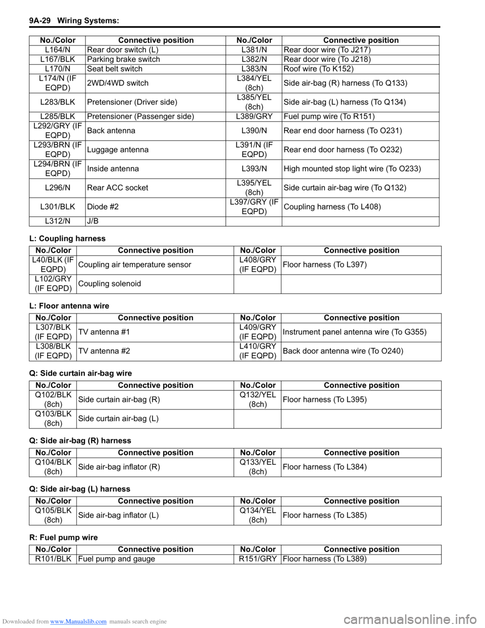
Downloaded from www.Manualslib.com manuals search engine 9A-29 Wiring Systems:
L: Coupling harness
L: Floor antenna wire
Q: Side curtain air-bag wire
Q: Side air-bag (R) harness
Q: Side air-bag (L) harness
R: Fuel pump wireL164/N Rear door switch (L) L381/N Rear door wire (To J217)
L167/BLK Parking brake switch L382/N Rear door wire (To J218)
L170/N Seat belt switch L383/N Roof wire (To K152)
L174/N (IF
EQPD)2WD/4WD switchL384/YEL
(8ch)Side air-bag (R) harness (To Q133)
L283/BLK Pretensioner (Driver side)L385/YEL
(8ch)Side air-bag (L) harness (To Q134)
L285/BLK Pretensioner (Passenger side) L389/GRY Fuel pump wire (To R151)
L292/GRY (IF
EQPD)Back antenna L390/N Rear end door harness (To O231)
L293/BRN (IF
EQPD)Luggage antennaL391/N (IF
EQPD)Rear end door harness (To O232)
L294/BRN (IF
EQPD)Inside antenna L393/N High mounted stop light wire (To O233)
L296/N Rear ACC socketL395/YEL
(8ch)Side curtain air-bag wire (To Q132)
L301/BLK Diode #2L397/GRY (IF
EQPD)Coupling harness (To L408)
L312/N J/B No./Color Connective position No./Color Connective position
No./Color Connective position No./Color Connective position
L40/BLK (IF
EQPD)Coupling air temperature sensorL408/GRY
(IF EQPD)Floor harness (To L397)
L102/GRY
(IF EQPD)Coupling solenoid
No./Color Connective position No./Color Connective position
L307/BLK
(IF EQPD)TV antenna #1L409/GRY
(IF EQPD)Instrument panel antenna wire (To G355)
L308/BLK
(IF EQPD)TV antenna #2L410/GRY
(IF EQPD)Back door antenna wire (To O240)
No./Color Connective position No./Color Connective position
Q102/BLK
(8ch)Side curtain air-bag (R)Q132/YEL
(8ch)Floor harness (To L395)
Q103/BLK
(8ch)Side curtain air-bag (L)
No./Color Connective position No./Color Connective position
Q104/BLK
(8ch)Side air-bag inflator (R)Q133/YEL
(8ch)Floor harness (To L384)
No./Color Connective position No./Color Connective position
Q105/BLK
(8ch)Side air-bag inflator (L)Q134/YEL
(8ch)Floor harness (To L385)
No./Color Connective position No./Color Connective position
R101/BLK Fuel pump and gauge R151/GRY Floor harness (To L389)
Page 1197 of 1556
Downloaded from www.Manualslib.com manuals search engine Wiring Systems: 9A-30
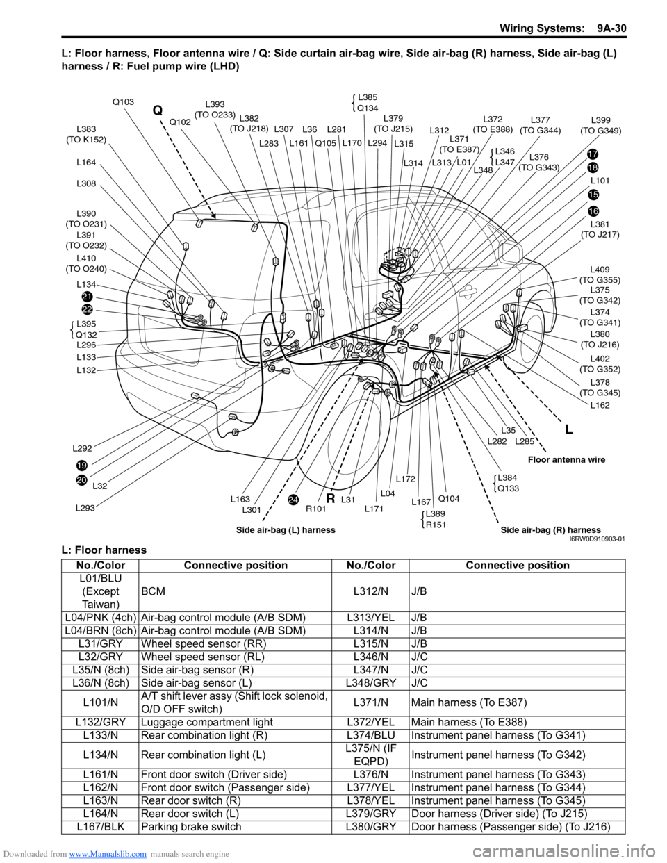
L: Floor harness, Floor antenna wire / Q: Side curtain air-bag wire, Side air-bag (R) harness, Side air-bag (L)
harness / R: Fuel pump wire (LHD)
L: Floor harness
21
22
20
24
19
17
18
15
16
L383
(TO K152)
L390
(TO O231)
L391
(TO O232)
L410
(TO O240)
L164
L308
L134
L292
L293
L32
L132
L133
L296L381
(TO J217)
L375
(TO G342)
L402
(TO G352)
L374
(TO G341)L409
(TO G355)
L380
(TO J216)
L378
(TO G345)
L162
L285L282
L35
L36L281 L307
L301
Q105
R101L171
L294 L170
L31L167Q104L04
L172
Q103
L382
(TO J218)
L376
(TO G343)L379
(TO J215)
L371
(TO E387)
L372
(TO E388)L377
(TO G344)Q102
L161L283
L163
L101L348
L399
(TO G349)
L314
L315
L312
L313
L01
L395
Q132
L385
Q134L393
(TO O233)
L346
L347
L389
R151
L384
Q133
L
R Q
Side air-bag (R) harnessFloor antenna wire
Side air-bag (L) harnessI6RW0D910903-01
No./Color Connective position No./Color Connective position
L01/BLU
(Except
Ta i w a n )BCM L312/N J/B
L04/PNK (4ch) Air-bag control module (A/B SDM) L313/YEL J/B
L04/BRN (8ch) Air-bag control module (A/B SDM) L314/N J/B
L31/GRY Wheel speed sensor (RR) L315/N J/B
L32/GRY Wheel speed sensor (RL) L346/N J/C
L35/N (8ch) Side air-bag sensor (R) L347/N J/C
L36/N (8ch) Side air-bag sensor (L) L348/GRY J/C
L101/NA/T shift lever assy (Shift lock solenoid,
O/D OFF switch)L371/N Main harness (To E387)
L132/GRY Luggage compartment light L372/YEL Main harness (To E388)
L133/N Rear combination light (R) L374/BLU Instrument panel harness (To G341)
L134/N Rear combination light (L)L375/N (IF
EQPD)Instrument panel harness (To G342)
L161/N Front door switch (Driver side) L376/N Instrument panel harness (To G343)
L162/N Front door switch (Passenger side) L377/YEL Instrument panel harness (To G344)
L163/N Rear door switch (R) L378/YEL Instrument panel harness (To G345)
L164/N Rear door switch (L) L379/GRY Door harness (Driver side) (To J215)
L167/BLK Parking brake switch L380/GRY Door harness (Passenger side) (To J216)
Page 1273 of 1556
Downloaded from www.Manualslib.com manuals search engine Wiring Systems: 9A-106
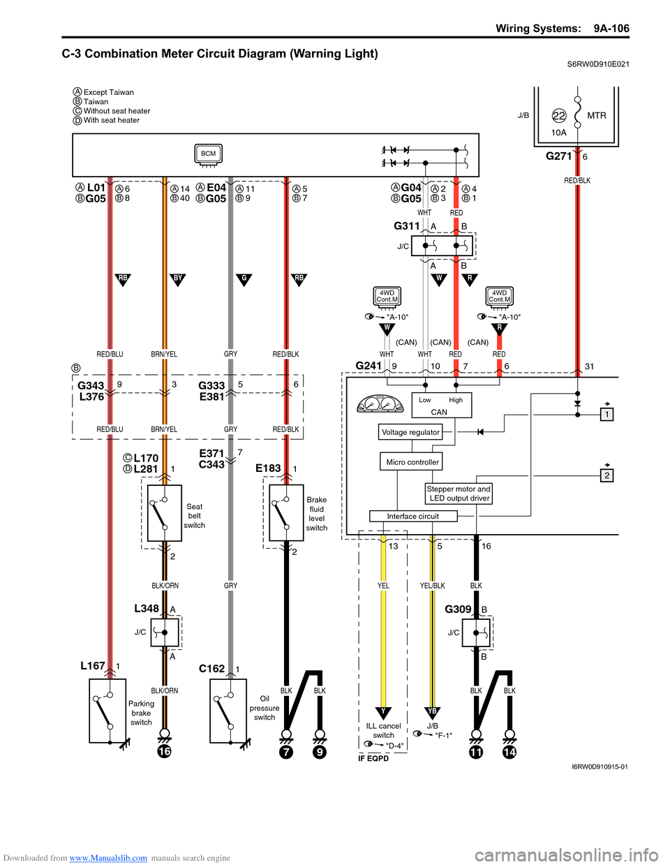
C-3 Combination Meter Circuit Diagram (Warning Light)S6RW0D910E021
J/BMTR
10A22
31
Stepper motor and
LED output driver
Voltage regulator
Micro controller
G2716
RED/BLK
516
YB
YEL/BLK
"F-1"
CAN
High Low
WHTWHTRED
RW
10G2419
7
L01
G05
RED/BLUBRN/YEL
L1671
Parking
brake
switch
1
2
A
A
16
BLK/ORN
BLK/ORN
J/C
L348B
B
J/C
G309
Seat
belt
switch
Oil
pressure
switch
J/B
13
Y
YEL
"D-4"
ILL cancel
switch
E371
C3437
G343
L37693G333
E38156
GRY
GRY
1C162
RED/BLK
RED/BLUBRN/YELGRYRED/BLK
E1831
Brake
fluid
level
switch
2
71114
BLK
BLK
BLK
9
BLKBLK
W
WHTRED
1
2
A
AB
B
J/C
G311
RBGBYRB
BCM
"A-10"
4WD
Cont.M
Interface circuit
RED
6
R"A-10"
4WD
Cont.M
(CAN) (CAN) (CAN)
IF EQPD
Except Taiwan
Taiwan
Without seat heater
With seat heater A
A
B
L170
L281C
D
G04
G05A
BE04
G05A
B
BCD
B
6
8AB14
40AB11
9AB5
7AB2
3AB4
1AB
I6RW0D910915-01
Page 1308 of 1556
Downloaded from www.Manualslib.com manuals search engine 9A-141 Wiring Systems:
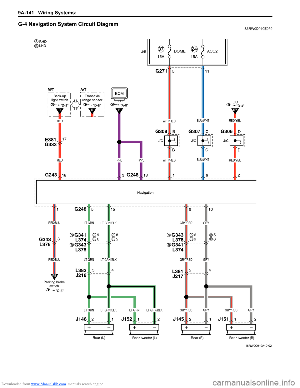
G-4 Navigation System Circuit DiagramS6RW0D910E059
G2715
5
4
11
2
12
1 5
156
16
"D-4"RY
WHT/RED
WHT/RED
G248
G2481
G307
J/B
15ADOME
37
J/C
BLU/WHT
BLU/WHTRED/YEL
15AACC2
24
Rear (R)
J/C
Rear (L)
GRY/REDGRYLT GRN/BLKLT GRN
GRY/REDGRYLT GRN/BLKLT GRN
GRY/REDGRYLT GRN/BLKLT GRN
1
Navigation
RED/YEL
92
J146
C
CG308
J/C
B
BG306
J/C
D
D
PPLPPL
18G243183
L381
J2175
4L382
J218
J145
G341
L374
G343
L376
1
2
Rear tweeter (R)
GRY/REDGRY
J1511
2
Rear tweeter (L)
LT GRNLT GRN/BLK
J152
A
B
G343
L376
G341
L374A
B
9
6AB8
5AB6
9AB5
8AB
M/T
RED/BLU
RED/BLU
Parking brake
switchBack-up
light switch
"C-3"
RB
"A-8"P
BCM
RED
RED
"D-8"R
E381
G33317
G343
L3763
A/T
Transaxle
range sensor
"D-8"
R
RHD
LHD AB
I6RW0C910A10-02
Page 1354 of 1556
Downloaded from www.Manualslib.com manuals search engine 9C-2 Instrumentation / Driver Info. / Horn:
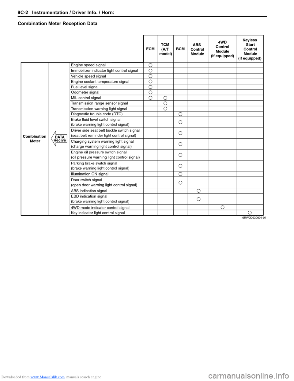
Combination Meter Reception Data
ECM BCM
Keyless
Start
Control
Module
(if equipped)
Combination
Meter4WD
Control
Module
(if equipped)TCM
(A/T
model)
Engine speed signal
Immobilizer indicator light control signal
Vehicle speed signal
Engine coolant temperature signal
Fuel level signal
MIL control signal
Transmission range sensor signal
Transmission warning light signal
Diagnostic trouble code (DTC)
Brake fluid level switch signal
(brake warning light control signal)
Driver side seat belt buckle switch signal
(seat belt reminder light control signal)
Charging system warning light signal
(charge warning light control signal)
Engine oil pressure switch signal
(oil pressure warning light control signal)
Parking brake switch signal
(brake warning light control signal)
Illumination ON signal
Door switch signal
(open door warning light control signal)
ABS indication signal
EBD indication signal
(brake warning light control signal)
4WD mode indicator control signal
Key indicator light control signal
ABS
Control
Module
Odometer signal
DATA
Recive
I6RW0D930001-01
Page 1360 of 1556
Downloaded from www.Manualslib.com manuals search engine 9C-8 Instrumentation / Driver Info. / Horn:
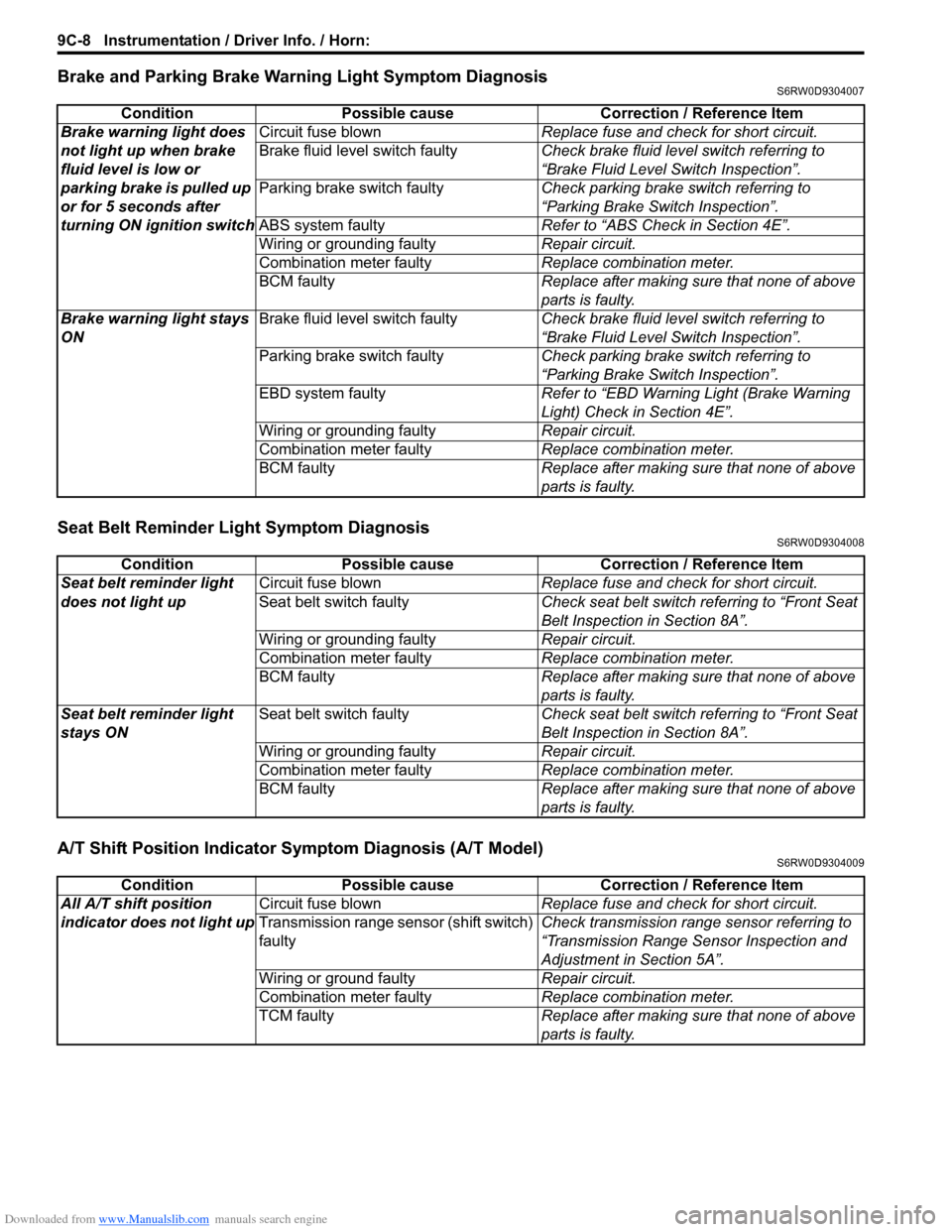
Brake and Parking Brake Warning Light Symptom DiagnosisS6RW0D9304007
Seat Belt Reminder Light Symptom DiagnosisS6RW0D9304008
A/T Shift Position Indicator Symptom Diagnosis (A/T Model)S6RW0D9304009
Condition Possible cause Correction / Reference Item
Brake warning light does
not light up when brake
fluid level is low or
parking brake is pulled up
or for 5 seconds after
turning ON ignition switchCircuit fuse blownReplace fuse and check for short circuit.
Brake fluid level switch faultyCheck brake fluid level switch referring to
“Brake Fluid Level Switch Inspection”.
Parking brake switch faultyCheck parking brake switch referring to
“Parking Brake Switch Inspection”.
ABS system faultyRefer to “ABS Check in Section 4E”.
Wiring or grounding faultyRepair circuit.
Combination meter faultyReplace combination meter.
BCM faultyReplace after making sure that none of above
parts is faulty.
Brake warning light stays
ONBrake fluid level switch faultyCheck brake fluid level switch referring to
“Brake Fluid Level Switch Inspection”.
Parking brake switch faultyCheck parking brake switch referring to
“Parking Brake Switch Inspection”.
EBD system faultyRefer to “EBD Warning Light (Brake Warning
Light) Check in Section 4E”.
Wiring or grounding faultyRepair circuit.
Combination meter faultyReplace combination meter.
BCM faultyReplace after making sure that none of above
parts is faulty.
Condition Possible cause Correction / Reference Item
Seat belt reminder light
does not light upCircuit fuse blownReplace fuse and check for short circuit.
Seat belt switch faultyCheck seat belt switch referring to “Front Seat
Belt Inspection in Section 8A”.
Wiring or grounding faultyRepair circuit.
Combination meter faultyReplace combination meter.
BCM faultyReplace after making sure that none of above
parts is faulty.
Seat belt reminder light
stays ONSeat belt switch faultyCheck seat belt switch referring to “Front Seat
Belt Inspection in Section 8A”.
Wiring or grounding faultyRepair circuit.
Combination meter faultyReplace combination meter.
BCM faultyReplace after making sure that none of above
parts is faulty.
Condition Possible cause Correction / Reference Item
All A/T shift position
indicator does not light upCircuit fuse blownReplace fuse and check for short circuit.
Transmission range sensor (shift switch)
faultyCheck transmission range sensor referring to
“Transmission Range Sensor Inspection and
Adjustment in Section 5A”.
Wiring or ground faultyRepair circuit.
Combination meter faultyReplace combination meter.
TCM faultyReplace after making sure that none of above
parts is faulty.
Page 1474 of 1556
Downloaded from www.Manualslib.com manuals search engine 10B-1 Body Electrical Control System:
Control Systems
Body Electrical Control System
Precautions
Precautions in Diagnosing TroubleS6RW0DA200001
• Diagnostic information stored in BCM memory can be cleared as well as checked by using SUZUKI scan tool.
Before using scan tool, read its Operator’s (Instruction) Manual carefully to have good understanding as to what
functions are available and how to use it.
• Be sure to read “Precautions for Electrical Circuit Service in Section 00” before inspection and observe what is
written there.
• Communication of ECM, TCM (A/T model), ABS control module, 4WD control module (if equipped), keyless start
control module (if equipped), combination meter and BCM is established by CAN (Controller Area Network). For
detail of CAN communication for BCM, refer to “CAN Communication System Description”. Therefore, handle CAN
communication line with care referring to “Precaution for CAN Communication System in Section 00”.
General Description
BCM General DescriptionS6RW0DA201001
The Body electrical Control Module (BCM) is
incorporated in junction block. Do not attempt removal of
BCM from junction block as it may cause contact failure.
The BCM incorporates relays and controllers which are
used for the following systems and controls them.
• Power door lock (if equipped)
• Keyless entry (if equipped)
• Door lock function of keyless start system (if
equipped)
• Rear wiper
• Combination meter
• Interior light• Warning buzzer
• Rear end door window defogger and door mirror
heater (if equipped)
• Rear end door opener (if equipped)
• Theft deterrent light
Also, the BCM has a function to cause the interior light
and open door warning light in the combination meter to
turn off when any door is left open for longer than 15
minutes to reduce wasteful battery consumption.
In addition, it is possible to check operation of actuator
which is controlled by BCM by using the output test
function of SUZUKI scan tool to operate actuator
simulatively.
CAN Communication System DescriptionS6RW0DA201002
Refer to “CAN Communication System Description in Section 1A” for CAN communication system description.
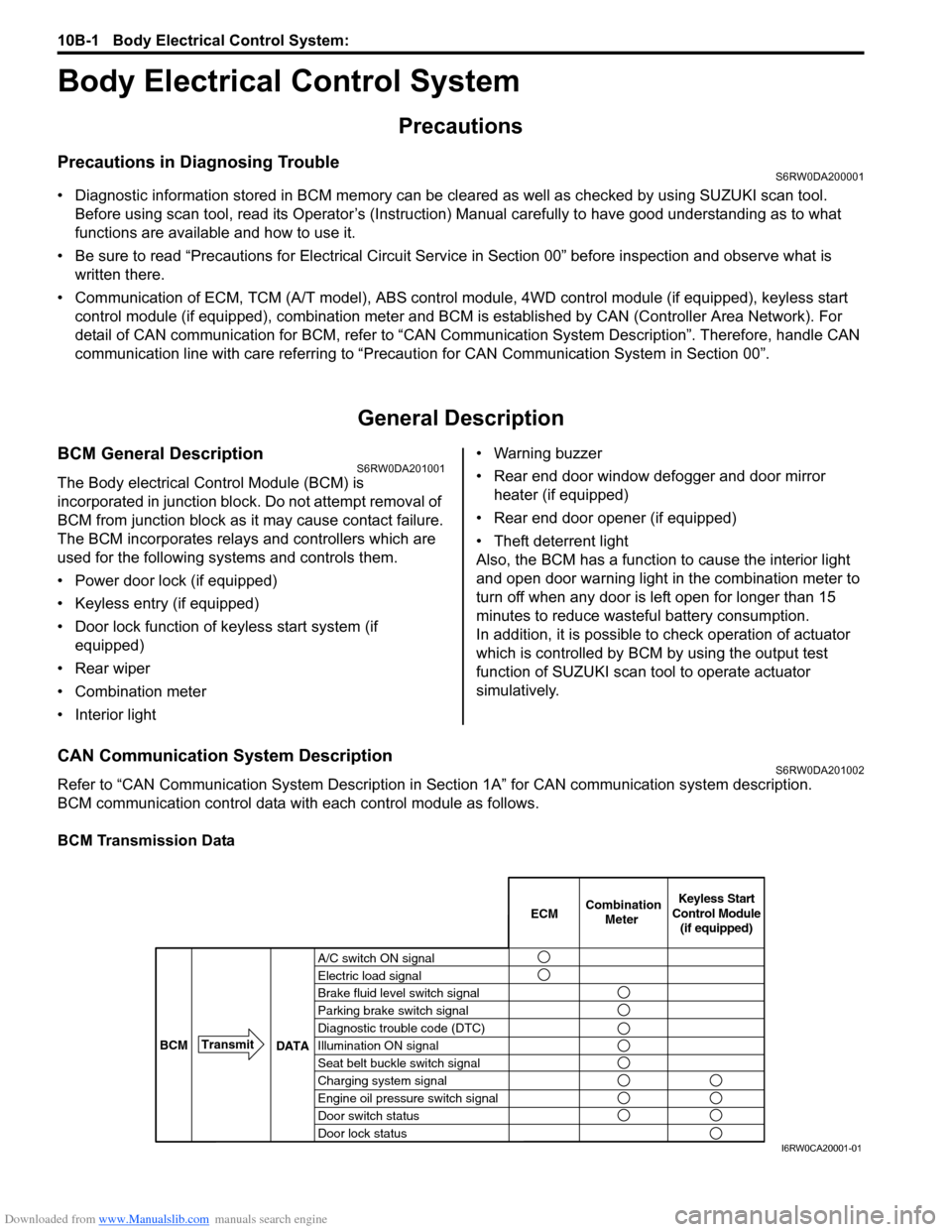
BCM communication control data with each control module as follows.
BCM Transmission Data
A/C switch ON signal
Electric load signal
Brake fluid level switch signal
Parking brake switch signal
Diagnostic trouble code (DTC)
Illumination ON signal
Seat belt buckle switch signal
Charging system signal
Engine oil pressure switch signal
Door switch status
Door lock statusECMKeyless Start
Control Module
(if equipped) Combination
Meter
BCMTransmit
DATA
I6RW0CA20001-01