2006 SUZUKI SX4 Oil ring
[x] Cancel search: Oil ringPage 838 of 1556
Downloaded from www.Manualslib.com manuals search engine 5B-26 Manual Transmission/Transaxle:
Reassembly
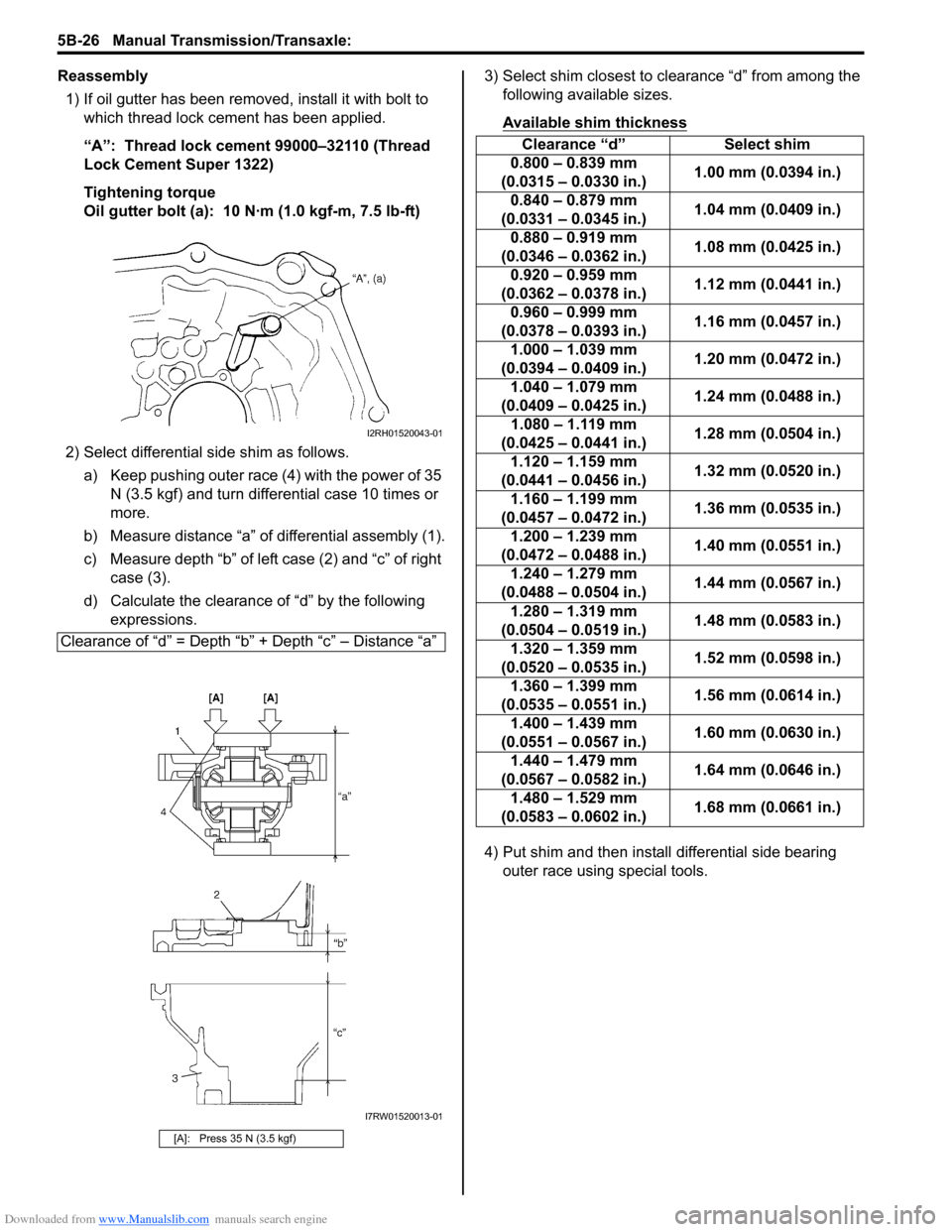
1) If oil gutter has been removed, install it with bolt to
which thread lock cement has been applied.
“A”: Thread lock cement 99000–32110 (Thread
Lock Cement Super 1322)
Tightening torque
Oil gutter bolt (a): 10 N·m (1.0 kgf-m, 7.5 lb-ft)
2) Select differential side shim as follows.
a) Keep pushing outer race (4) with the power of 35
N (3.5 kgf) and turn differential case 10 times or
more.
b) Measure distance “a” of differential assembly (1).
c) Measure depth “b” of left case (2) and “c” of right
case (3).
d) Calculate the clearance of “d” by the following
expressions.3) Select shim closest to clearance “d” from among the
following available sizes.
Available shim thickness
4) Put shim and then install differential side bearing
outer race using special tools. Clearance of “d” = Depth “b” + Depth “c” – Distance “a”
[A]: Press 35 N (3.5 kgf)
I2RH01520043-01
I7RW01520013-01
Clearance “d” Select shim
0.800 – 0.839 mm
(0.0315 – 0.0330 in.)1.00 mm (0.0394 in.)
0.840 – 0.879 mm
(0.0331 – 0.0345 in.)1.04 mm (0.0409 in.)
0.880 – 0.919 mm
(0.0346 – 0.0362 in.)1.08 mm (0.0425 in.)
0.920 – 0.959 mm
(0.0362 – 0.0378 in.)1.12 mm (0.0441 in.)
0.960 – 0.999 mm
(0.0378 – 0.0393 in.)1.16 mm (0.0457 in.)
1.000 – 1.039 mm
(0.0394 – 0.0409 in.)1.20 mm (0.0472 in.)
1.040 – 1.079 mm
(0.0409 – 0.0425 in.)1.24 mm (0.0488 in.)
1.080 – 1.119 mm
(0.0425 – 0.0441 in.)1.28 mm (0.0504 in.)
1.120 – 1.159 mm
(0.0441 – 0.0456 in.)1.32 mm (0.0520 in.)
1.160 – 1.199 mm
(0.0457 – 0.0472 in.)1.36 mm (0.0535 in.)
1.200 – 1.239 mm
(0.0472 – 0.0488 in.)1.40 mm (0.0551 in.)
1.240 – 1.279 mm
(0.0488 – 0.0504 in.)1.44 mm (0.0567 in.)
1.280 – 1.319 mm
(0.0504 – 0.0519 in.)1.48 mm (0.0583 in.)
1.320 – 1.359 mm
(0.0520 – 0.0535 in.)1.52 mm (0.0598 in.)
1.360 – 1.399 mm
(0.0535 – 0.0551 in.)1.56 mm (0.0614 in.)
1.400 – 1.439 mm
(0.0551 – 0.0567 in.)1.60 mm (0.0630 in.)
1.440 – 1.479 mm
(0.0567 – 0.0582 in.)1.64 mm (0.0646 in.)
1.480 – 1.529 mm
(0.0583 – 0.0602 in.)1.68 mm (0.0661 in.)
Page 839 of 1556
Downloaded from www.Manualslib.com manuals search engine Manual Transmission/Transaxle: 5B-27
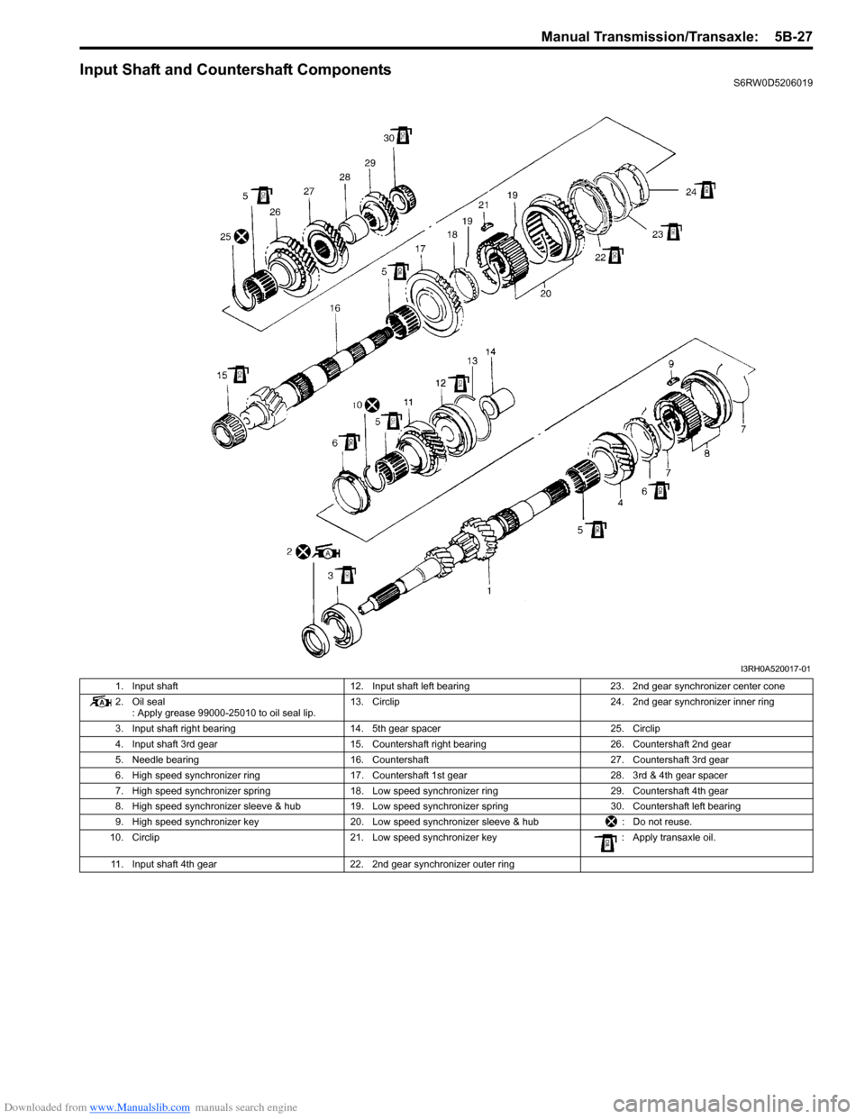
Input Shaft and Countershaft ComponentsS6RW0D5206019
I3RH0A520017-01
1. Input shaft 12. Input shaft left bearing 23. 2nd gear synchronizer center cone
2. Oil seal
: Apply grease 99000-25010 to oil seal lip.13. Circlip 24. 2nd gear synchronizer inner ring
3. Input shaft right bearing 14. 5th gear spacer 25. Circlip
4. Input shaft 3rd gear 15. Countershaft right bearing 26. Countershaft 2nd gear
5. Needle bearing 16. Countershaft 27. Countershaft 3rd gear
6. High speed synchronizer ring 17. Countershaft 1st gear 28. 3rd & 4th gear spacer
7. High speed synchronizer spring 18. Low speed synchronizer ring 29. Countershaft 4th gear
8. High speed synchronizer sleeve & hub 19. Low speed synchronizer spring 30. Countershaft left bearing
9. High speed synchronizer key 20. Low speed synchronizer sleeve & hub : Do not reuse.
10. Circlip 21. Low speed synchronizer key : Apply transaxle oil.
11. Input shaft 4th gear 22. 2nd gear synchronizer outer ring
Page 841 of 1556
Downloaded from www.Manualslib.com manuals search engine Manual Transmission/Transaxle: 5B-29
Reassembly
1) Clean all components thoroughly, inspect them for
any abnormality and replace with new ones as
necessary.
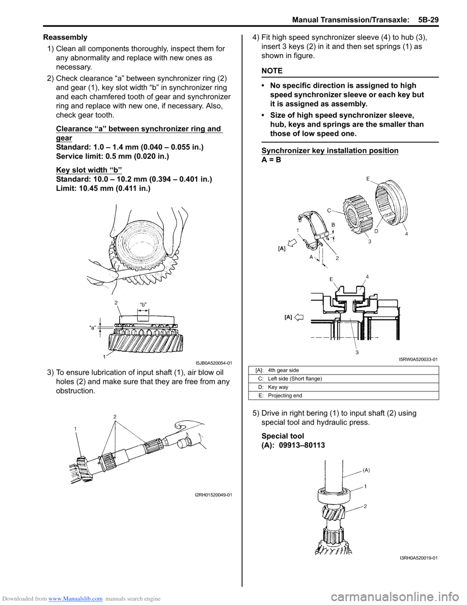
2) Check clearance “a” between synchronizer ring (2)
and gear (1), key slot width “b” in synchronizer ring
and each chamfered tooth of gear and synchronizer
ring and replace with new one, if necessary. Also,
check gear tooth.
Clearance “a” between synchronizer ring and
gear
Standard: 1.0 – 1.4 mm (0.040 – 0.055 in.)
Service limit: 0.5 mm (0.020 in.)
Key slot width “b”
Standard: 10.0 – 10.2 mm (0.394 – 0.401 in.)
Limit: 10.45 mm (0.411 in.)
3) To ensure lubrication of input shaft (1), air blow oil
holes (2) and make sure that they are free from any
obstruction.4) Fit high speed synchronizer sleeve (4) to hub (3),
insert 3 keys (2) in it and then set springs (1) as
shown in figure.
NOTE
• No specific direction is assigned to high
speed synchronizer sleeve or each key but
it is assigned as assembly.
• Size of high speed synchronizer sleeve,
hub, keys and springs are the smaller than
those of low speed one.
Synchronizer key installation position
A = B
5) Drive in right bering (1) to input shaft (2) using
special tool and hydraulic press.
Special tool
(A): 09913–80113
I5JB0A520054-01
I2RH01520049-01
[A]: 4th gear side
C: Left side (Short flange)
D: Key way
E: Projecting end
I5RW0A520033-01
I3RH0A520019-01
Page 842 of 1556
Downloaded from www.Manualslib.com manuals search engine 5B-30 Manual Transmission/Transaxle:
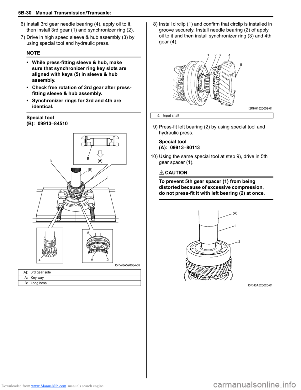
6) Install 3rd gear needle bearing (4), apply oil to it,
then install 3rd gear (1) and synchronizer ring (2).
7) Drive in high speed sleeve & hub assembly (3) by
using special tool and hydraulic press.
NOTE
• While press-fitting sleeve & hub, make
sure that synchronizer ring key slots are
aligned with keys (5) in sleeve & hub
assembly.
• Check free rotation of 3rd gear after press-
fitting sleeve & hub assembly.
• Synchronizer rings for 3rd and 4th are
identical.
Special tool
(B): 09913–845108) Install circlip (1) and confirm that circlip is installed in
groove securely. Install needle bearing (2) of apply
oil to it and then install synchronizer ring (3) and 4th
gear (4).
9) Press-fit left bearing (2) by using special tool and
hydraulic press.
Special tool
(A): 09913–80113
10) Using the same special tool at step 9), drive in 5th
gear spacer (1).
CAUTION!
To prevent 5th gear spacer (1) from being
distorted because of excessive compression,
do not press-fit it with left bearing (2) at once.
[A]: 3rd gear side
A: Key way
B: Long boss
B
[A]3
(B)
4A 5
21
I5RW0A520034-02
5. Input shaft
I2RH01520052-01
I3RH0A520020-01
Page 844 of 1556

Downloaded from www.Manualslib.com manuals search engine 5B-32 Manual Transmission/Transaxle:
6) Disassemble synchronizer sleeve & hub assembly.
7) Take out 1st gear needle bearing from shaft.
8) In order to remove right bearing (1) from
countershaft, grind with a grinder (2) one part “a” of
right bearing (1) as illustrated till it becomes thin.
CAUTION!
Be careful not to grind too far not to damage
the shaft (3).
9) Break with a chisel (1) the thin ground right bearing
(2) and it can be removed.
Reassembly
1) Clean all components thoroughly, inspect them for
any abnormality and replace with new one as
necessary.
2) Check clearance “a” between synchronizer ring (2)
and gear (1), key slot width “b” in synchronizer ring
and each chamfered tooth of gear and synchronizer
ring and replace with new one, if necessary. Also,
check gear tooth.
Clearance “a” between synchronizer ring and
gear
Standard: 1.0 – 1.4 mm (0.040 – 0.055 in.)
Service limit: 0.5 mm (0.020 in.)
Key slot width “b”
Standard: 10.0 – 10.2 mm (0.394 – 0.401 in.)
Limit: 10.45 mm (0.411 in.)3) Put the synchronizer outer ring (1), inner ring (3) and
the cone (2) together and then measure the step
difference between the outer ring and the inner ring.
And also check each chamfered tooth of gear and
synchronizer ring and replace with new one, if
necessary. Also, check gear tooth.
Difference between synchronizer outer ring and
inner ring (2nd)
Standard “b”: 0.95 – 1.25 mm (0.036 – 0.048 in.)
Service limit “b”: 0.5 mm (0.019 in.)
4) To ensure lubrication of countershaft (1), air blow oil
holes (2) and make sure that they are free from any
obstruction.
3
1
2
“a”31
I5RW0A520035-01
1
2I5RW0A520036-01
I5JB0A520079-01
I2RH01520059-01
I2RH01520060-01
Page 845 of 1556
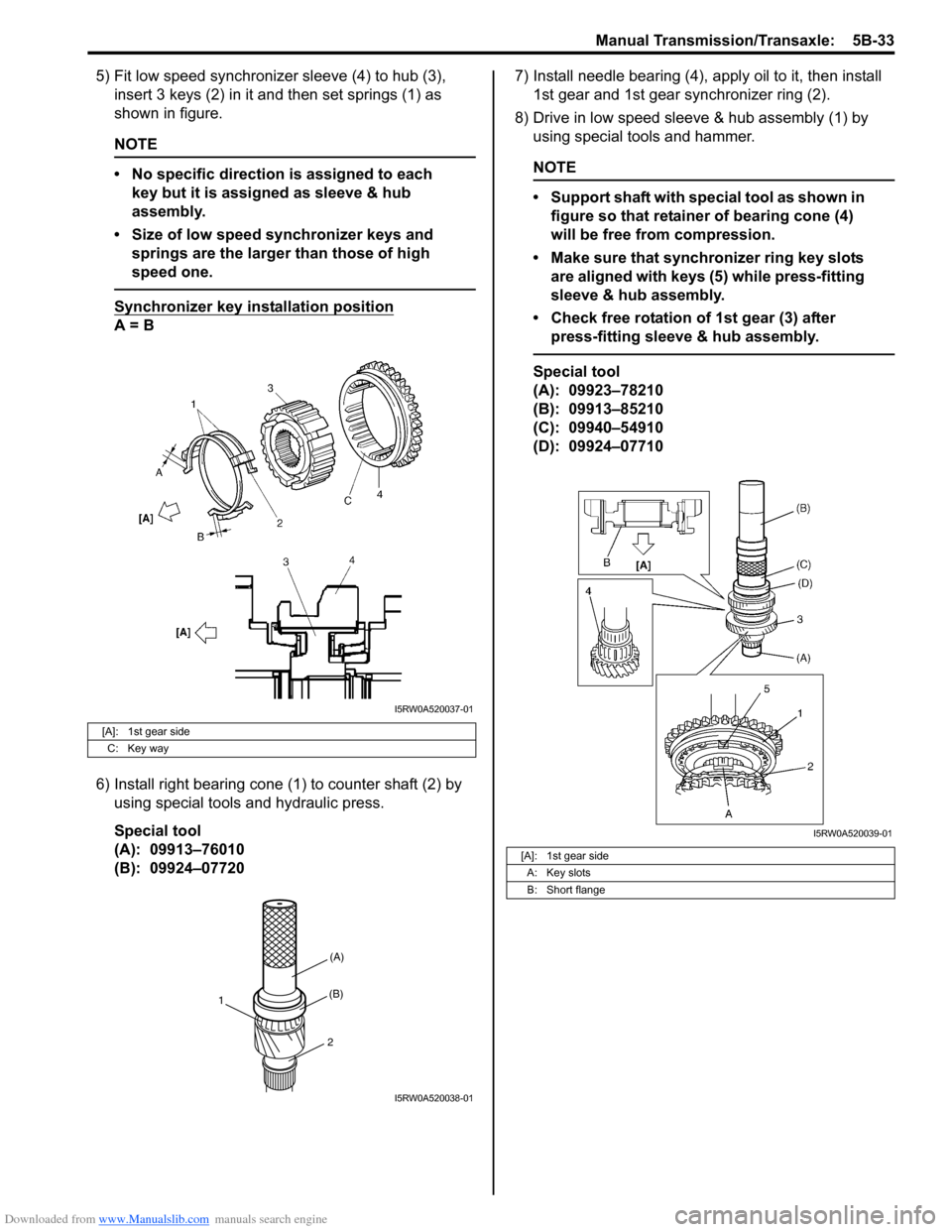
Downloaded from www.Manualslib.com manuals search engine Manual Transmission/Transaxle: 5B-33
5) Fit low speed synchronizer sleeve (4) to hub (3),
insert 3 keys (2) in it and then set springs (1) as
shown in figure.
NOTE
• No specific direction is assigned to each
key but it is assigned as sleeve & hub
assembly.
• Size of low speed synchronizer keys and
springs are the larger than those of high
speed one.
Synchronizer key installation position
A = B
6) Install right bearing cone (1) to counter shaft (2) by
using special tools and hydraulic press.
Special tool
(A): 09913–76010
(B): 09924–077207) Install needle bearing (4), apply oil to it, then install
1st gear and 1st gear synchronizer ring (2).
8) Drive in low speed sleeve & hub assembly (1) by
using special tools and hammer.
NOTE
• Support shaft with special tool as shown in
figure so that retainer of bearing cone (4)
will be free from compression.
• Make sure that synchronizer ring key slots
are aligned with keys (5) while press-fitting
sleeve & hub assembly.
• Check free rotation of 1st gear (3) after
press-fitting sleeve & hub assembly.
Special tool
(A): 09923–78210
(B): 09913–85210
(C): 09940–54910
(D): 09924–07710
[A]: 1st gear side
C: Key way
I5RW0A520037-01
(A)
(B)
2
1
I5RW0A520038-01
[A]: 1st gear side
A: Key slots
B: Short flange
I5RW0A520039-01
Page 846 of 1556

Downloaded from www.Manualslib.com manuals search engine 5B-34 Manual Transmission/Transaxle:
9) Install circlip (1) and confirm that circlip is installed in
groove securely.
Install needle bearing (2) and apply oil to needle
bearing.
With synchronizer outer ring (3), center cone (4) and
inner ring (5) put together and installed to 2nd gear
(6) as shown in figure.
10) Press-fit 3rd gear (2) and spacer (1) by using special
tools and hydraulic press.
NOTE
It is recommended to press-fit spacer and 3rd
gear first, and then 4th gear later separately
so that countershaft will not be compressed
excessively.
Special tool
(A): 09923–78210
(B): 09913–8521011) Press-fit 4th gear (2) by using the same procedure at
step 10).
12) Install left bearing cone (1) by using special tool and
hydraulic press.
NOTE
For protection of bearing cone (3), always
support shaft with special tool as shown in
figure.
Special tool
(A): 09923–78210
(E): 09913–80113
[A]: Section A – A
3. 2nd gear
I5RW0A520040-01
I4RH01520036-01
I2RH01520066-01
Page 847 of 1556

Downloaded from www.Manualslib.com manuals search engine Manual Transmission/Transaxle: 5B-35
Gear Shift Shaft ComponentsS6RW0D5206022
5th and Reverse Gear Shift Shafts Disassembly
and Reassembly
S6RW0D5206023
Disassembly
Disassemble component parts by using special tool and
hammer.
Special tool
: 09922–85811
Reassembly
Replace or correct parts as required and assemble
shafts making sure that component parts are in proper
order as shown in figure.
NOTE
Install 2 steel balls (3) in reverse gear shift
arm (1) without fail.
Gear Shift Shaft and Fork InspectionS6RW0D5206024
1) Using feeler gauge, check clearance between fork
(1) and sleeve (2) and replace those parts if it
exceeds limit of 1.0 mm (0.039 in.).
NOTE
For correct judgement of parts replacement,
carefully inspect contact portion of fork and
sleeve.
Clearance “a” between fork and sleeve
Service limit: 1.0 mm (0.039 in.)
2) Insert each gear shift shaft into case and check that
it moves smoothly. If it doesn’t, correct by using
oilstone, reamer or the like.
I5RW0A520041-01
1. Low speed gear shift shaft 4. 5th & reverse gear shift guide shaft 7. 5th & reverse gear shift yoke
2. High speed gear shift shaft 5. Reverse gear shift arm : 13 N⋅m (1.3 kgf-m, 9.5 lb-ft)
3. 5th & reverse gear shift shaft 6. Gear shift locating bolt
: Apply sealant 99000-31260 to bolt thread.
2. Spring 6. 5th & reverse gear shift yoke
4. Spring pin 7. 5th & reverse gear shift guide shaft
5. 5th & reverse gear shift shaft
I5RW0A520042-01
I2RH01520068-01