2006 SUZUKI SX4 Ac wiring
[x] Cancel search: Ac wiringPage 1110 of 1556
Downloaded from www.Manualslib.com manuals search engine 8B-71 Air Bag System:
DTC Troubleshooting
NOTE
Upon completion of inspection and repair work, perform the following items.
• Reconnect all air bag system components and ensure all components are properly mounted.
• Clear DTCs referring to “DTC Clearance”, if any.
• Repeat “Air Bag Diagnostic System Check” to confirm that the trouble has been corrected.
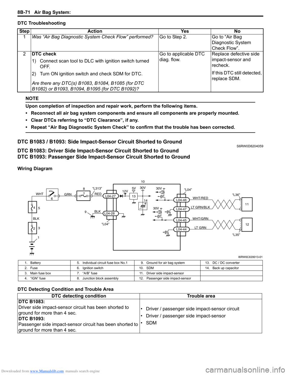
DTC B1083 / B1093: Side Impact-Sensor Circuit Shorted to GroundS6RW0D8204059
DTC B1083: Driver Side Impact-Sensor Circuit Shorted to Ground
DTC B1093: Passenger Side Impact-Sensor Circuit Shorted to Ground
Wiring Diagram
DTC Detecting Condition and Trouble AreaStep Action Yes No
1Was “Air Bag Diagnostic System Check Flow” performed?Go to Step 2. Go to “Air Bag
Diagnostic System
Check Flow”.
2DTC check
1) Connect scan tool to DLC with ignition switch turned
OFF.
2) Turn ON ignition switch and check SDM for DTC.
Are there any DTC(s) B1083, B1084, B1085 (for DTC
B1082) or B1093, B1094, B1095 (for DTC B1092)?Go to applicable DTC
diag. flow.Replace defective side
impact-sensor and
recheck.
If this DTC still detected,
replace SDM.
10
“L04”30V
30VL04-47 L04-46WHT/RED
LT GRN/BLK“L36”
11
L04-44 L04-45WHT/GRN
LT GRN
“L35”12
“L04”
BLK
L04-28
6 8
7
RED
GRN“L313”L04-27
9
1
2 BLKWHT3
4
5
13
12V5V30V
14
I6RW0C820013-01
1. Battery 5. Individual circuit fuse box No.1 9. Ground for air bag system 13. DC / DC converter
2. Fuse 6. Ignition switch 10. SDM 14. Back up capacitor
3. Main fuse box 7. “A/B” fuse 11. Driver side impact-sensor
4. “IGN” fuse 8. Junction block assembly 12. Passenger side impact-sensor
DTC detecting condition Trouble area
DTC B1083:
Driver side impact-sensor circuit has been shorted to
ground for more than 4 sec.
DTC B1093:
Passenger side impact-sensor circuit has been shorted to
ground for more than 4 sec.• Driver / passenger side impact-sensor circuit
• Driver / passenger side impact-sensor
•SDM
Page 1112 of 1556
Downloaded from www.Manualslib.com manuals search engine 8B-73 Air Bag System:
DTC B1084 / B1094: Side Impact-Sensor Circuit OpenS6RW0D8204060
DTC B1084: Driver Side Impact-Sensor Circuit Open
DTC B1094: Passenger Side Impact-Sensor Circuit Open
Wiring Diagram
Refer to “DTC B1083 / B1093: Side Impact-Sensor Circuit Shorted to Ground”.
DTC Detecting Condition and Trouble Area
DTC TroubleshootingDTC detecting condition Trouble area
DTC B1084:
Driver side impact-sensor circuit has been shorted to
power circuit or opened for more than 4 sec.
DTC B1094:
Passenger side impact-sensor circuit has been shorted to
power circuit or opened or more than 4 sec.• Driver / passenger side impact-sensor circuit
• Driver / passenger side impact-sensor
•SDM
Step Action Yes No
1Was “Air Bag Diagnostic System Check Flow” performed?Go to Step 2. Go to “Air Bag
Diagnostic System
Check Flow”.
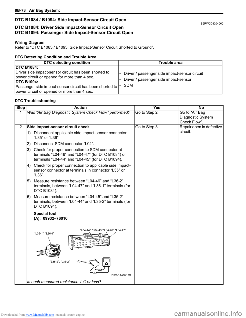
2Side impact-sensor circuit check
1) Disconnect applicable side impact-sensor connector
“L35” or “L36”.
2) Disconnect SDM connector “L04”.
3) Check for proper connection to SDM connector at
terminals “L04-46” and “L04-47” (for DTC B1084) or
terminals “L04-44” and “L04-45” (for DTC B1094).
4) Check for proper connection to applicable side impact-
sensor connector at terminals in connector “L35” or
“L36”.
5) Measure resistance between “L04-46” and “L36-2”
terminals, between “L04-47” and “L36-1” terminals (for
DTC B1084).
6) Measure resistance between “L04-45” and “L35-2”
terminals, between “L04-44” and “L35-2” terminals (for
DTC B1094).
Special tool
(A): 09932–76010
Is each measured resistance 1
Ω or less?Go to Step 3. Repair open in defective
circuit.
“L35-1”, “L36-1”
“L35-2”, “L36-2”
(A)
“L04-44”“L04-45” “L04-46” “L04-47”
I7RW01822071-01
Page 1114 of 1556
Downloaded from www.Manualslib.com manuals search engine 8B-75 Air Bag System:
NOTE
Upon completion of inspection and repair work, perform the following items.
• Reconnect all air bag system components and ensure all components are properly mounted.
• Clear DTCs referring to “DTC Clearance”, if any.
• Repeat “Air Bag Diagnostic System Check” to confirm that the trouble has been corrected.
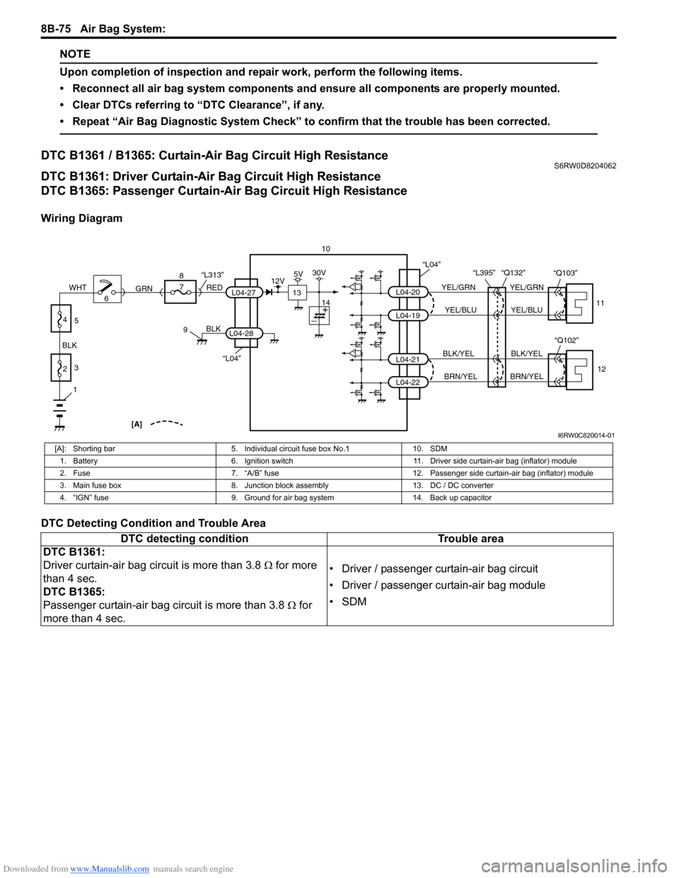
DTC B1361 / B1365: Curtain-Air Bag Circuit High ResistanceS6RW0D8204062
DTC B1361: Driver Curtain-Air Bag Circuit High Resistance
DTC B1365: Passenger Curtain-Air Bag Circuit High Resistance
Wiring Diagram
DTC Detecting Condition and Trouble Area
10
L04-20
L04-19
L04-21
L04-22
YEL/GRN
YEL/BLU
BLK/YEL
BRN/YELYEL/GRN
YEL/BLU
BLK/YEL
BRN/YEL “L395” “Q132”
11
12
“L04”
“Q102” “Q103”
“L04”
BLK
L04-28
6 8
7
RED
GRN“L313”L04-27
9
1
2 BLKWHT3
4
5
[A]
13
12V5V30V
14
I6RW0C820014-01
[A]: Shorting bar 5. Individual circuit fuse box No.1 10. SDM
1. Battery 6. Ignition switch 11. Driver side curtain-air bag (inflator) module
2. Fuse 7. “A/B” fuse 12. Passenger side curtain-air bag (inflator) module
3. Main fuse box 8. Junction block assembly 13. DC / DC converter
4. “IGN” fuse 9. Ground for air bag system 14. Back up capacitor
DTC detecting condition Trouble area
DTC B1361:
Driver curtain-air bag circuit is more than 3.8 Ω for more
than 4 sec.
DTC B1365:
Passenger curtain-air bag circuit is more than 3.8 Ω for
more than 4 sec.• Driver / passenger curtain-air bag circuit
• Driver / passenger curtain-air bag module
•SDM
Page 1118 of 1556
Downloaded from www.Manualslib.com manuals search engine 8B-79 Air Bag System:
DTC B1362 / B1366: Curtain-Air Bag Circuit Low ResistanceS6RW0D8204063
DTC B1362: Driver Curtain-Air Bag Circuit Low Resistance
DTC B1366: Passenger Curtain-Air Bag Circuit Low Resistance
Wiring Diagram
Refer to “DTC B1361 / B1365: Curtain-Air Bag Circuit High Resistance”.
DTC Detecting Condition and Trouble Area
DTC TroubleshootingDTC detecting condition Trouble area
DTC B1362:
Driver curtain-air bag circuit is less than 1.0 Ω for more
than 4 sec.
DTC B1366:
Passenger curtain-air bag circuit is less than 1.0 Ω for
more than 4 sec.• Driver / passenger curtain-air bag circuit
• Driver / passenger curtain-air bag module
•SDM
Step Action Yes No
1Was “Air Bag Diagnostic System Check Flow” performed?Go to Step 2. Go to “Air Bag
Diagnostic System
Check Flow”.
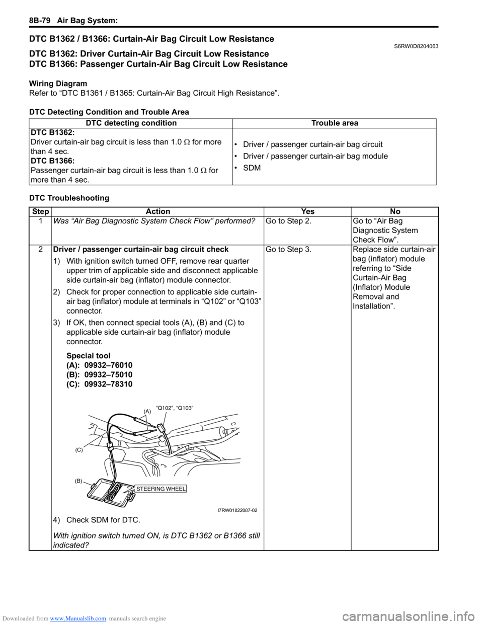
2Driver / passenger curtain-air bag circuit check
1) With ignition switch turned OFF, remove rear quarter
upper trim of applicable side and disconnect applicable
side curtain-air bag (inflator) module connector.
2) Check for proper connection to applicable side curtain-
air bag (inflator) module at terminals in “Q102” or “Q103”
connector.
3) If OK, then connect special tools (A), (B) and (C) to
applicable side curtain-air bag (inflator) module
connector.
Special tool
(A): 09932–76010
(B): 09932–75010
(C): 09932–78310
4) Check SDM for DTC.
With ignition switch turned ON, is DTC B1362 or B1366 still
indicated?Go to Step 3. Replace side curtain-air
bag (inflator) module
referring to “Side
Curtain-Air Bag
(Inflator) Module
Removal and
Installation”.
STEERING WHEEL(B)(C)
(A)“Q102”, “Q103”
I7RW01822087-02
Page 1120 of 1556
Downloaded from www.Manualslib.com manuals search engine 8B-81 Air Bag System:
DTC B1363 / B1367: Curtain-Air Bag Circuit Shorted to GroundS6RW0D8204064
DTC B1363: Driver Curtain-Air Bag Circuit Shorted to Ground
DTC B1367: Passenger Curtain-Air Bag Circuit Shorted to Ground
Wiring Diagram
Refer to “DTC B1361 / B1365: Curtain-Air Bag Circuit High Resistance”.
DTC Detecting Condition and Trouble Area
DTC TroubleshootingDTC detecting condition Trouble area
DTC B1363:
Driver curtain-air bag circuit has been shorted to ground
for more than 4 sec.
DTC B1367:
Passenger curtain-air bag circuit has been shorted to
ground for more than 4 sec.• Driver / passenger curtain-air bag circuit
•SDM
Step Action Yes No
1Was “Air Bag Diagnostic System Check Flow” performed?Go to Step 2. Go to “Air Bag
Diagnostic System
Check Flow”.
2Driver / passenger curtain-air bag circuit check
1) With ignition switch turned OFF, remove rear quarter
upper trim of applicable side and disconnect applicable
side curtain-air bag (inflator) module connector.
2) Disconnect SDM connector “L04”.
3) Check for proper connection to SDM connector at
terminal “L04-19” and “L04-20” (for DTC B1363) or
terminal “L04-21” and “L04-22” (For DTC B1367).
4) Check for proper connection to applicable side curtain-
air bag (inflator) module connector at terminal in its
connector.
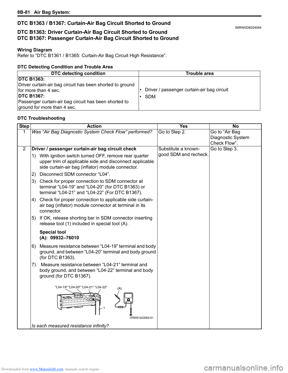
5) If OK, release shorting bar in SDM connector inserting
release tool (1) included in special tool (A).
Special tool
(A): 09932–76010
6) Measure resistance between “L04-19” terminal and body
ground, and between “L04-20” terminal and body ground
(for DTC B1363).
7) Measure resistance between “L04-21” terminal and
body ground, and between “L04-22” terminal and body
ground (for DTC B1367).
Is each measured resistance infinity?Substitute a known-
good SDM and recheck.Go to Step 3.
“L04-20” “L04-21” “L04-19”“L04-22”
1
(A)
I7RW01822092-01
Page 1122 of 1556
Downloaded from www.Manualslib.com manuals search engine 8B-83 Air Bag System:
DTC B1364 / B1368: Curtain-Air Bag Circuit Shorted to Power SupplyS6RW0D8204065
DTC B1364: Driver Curtain-Air Bag Circuit Shorted to Power Supply
DTC B1368: Passenger Curtain-Air Bag Circuit Shorted to Power Supply
Wiring Diagram
Refer to “DTC B1361 / B1365: Curtain-Air Bag Circuit High Resistance”.
DTC Detecting Condition and Trouble Area
DTC TroubleshootingDTC detecting condition Trouble area
DTC B1364:
Driver curtain-air bag circuit has been shorted to power
circuit for more than 4 sec.
DTC B1368:
Passenger curtain-air bag circuit has been shorted to
power circuit for more than 4 sec.• Driver / passenger curtain-air bag circuit
•SDM
Step Action Yes No
1Was “Air Bag Diagnostic System Check Flow” performed?Go to Step 2. Go to “Air Bag
Diagnostic System
Check Flow”.
2Driver / passenger curtain-air bag circuit check
1) With ignition switch turned OFF, remove rear quarter
upper trim of applicable side and disconnect applicable
side curtain-air bag (inflator) module connector.
2) Disconnect SDM connector “L04”.
3) Check for proper connection to SDM connector at
terminal “L04-19” and “L04-20” (for DTC B1364) or
terminal “L04-21” and “L04-22” (for DTC B1368).
4) Check for proper connection to applicable side curtain-
air bag (inflator) module its connector at terminal in its
connector.
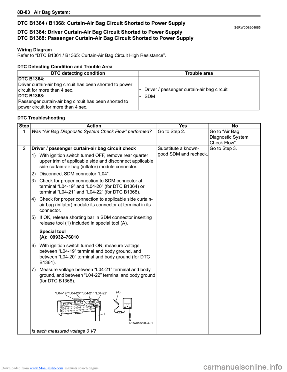
5) If OK, release shorting bar in SDM connector inserting
release tool (1) included in special tool (A).
Special tool
(A): 09932–76010
6) With ignition switch turned ON, measure voltage
between “L04-19” terminal and body ground, and
between “L04-20” terminal and body ground (for DTC
B1364).
7) Measure voltage between “L04-21” terminal and body
ground, and between “L04-22” terminal and body ground
(for DTC B1368).
Is each measured voltage 0 V?Substitute a known-
good SDM and recheck.Go to Step 3.
“L04-20” “L04-21” “L04-19”“L04-22”
1
(A)
I7RW01822094-01
Page 1124 of 1556
Downloaded from www.Manualslib.com manuals search engine 8B-85 Air Bag System:
SDM Power Supply and Ground Circuit CheckS6RW0D8204049
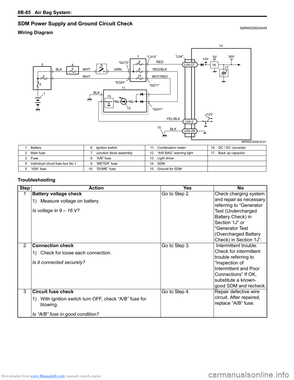
Wiring Diagram
Troubleshooting
“L04”14
5
9RED
RED/BLK GRN
YEL/BLK
BLK
8 7
11
12
15
L04-2
L04-28
L04-27
“G241” “G271” “L313”
13
12V
6
1BLK
WHT WHT
WHT/RED 2
34
310 BLK
“G273”
“E324”16
12V5V30V
17
I6RW0C820016-01
1. Battery 6. Ignition switch 11. Combination meter 16. DC / DC converter
2. Main fuse 7. Junction block assembly 12. “AIR BAG” warning light 17. Back up capacitor
3. Fuse 8. “A/B” fuse 13. Light driver
4. Individual circuit fuse box No.1 9. “METER” fuse 14. SDM
5. “IGN” fuse 10. “DOME” fuse 15. Ground for SDM
Step Action Yes No
1Battery voltage check
1) Measure voltage on battery.
Is voltage in 9 – 16 V?Go to Step 2. Check charging system
and repair as necessary
referring to “Generator
Test (Undercharged
Battery Check) in
Section 1J” or
“Generator Test
(Overcharged Battery
Check) in Section 1J”.
2Connection check
1) Check for loose each connection.
Is it connected securely?Go to Step 3. Intermittent trouble.
Check for intermittent
trouble referring to
“Inspection of
Intermittent and Poor
Connections” If OK,
substitute a known-
good SDM and recheck.
3Circuit fuse check
1) With ignition switch turn OFF, check “A/B” fuse for
blowing.
Is “A/B” fuse in good condition?Go to Step 4. Repair defective wire
circuit. After repaired,
replace “A/B” fuse.
Page 1128 of 1556
Downloaded from www.Manualslib.com manuals search engine 8B-89 Air Bag System:
Inspection of Intermittent and Poor
Connections
S6RW0D8204047
Most intermittents are caused by faulty electrical
connections or wiring. When a check for proper
connection is requested in a diagnostic flow, perform
careful check of suspect circuits.
If any abnormality is found, repair or replace as a wire
harness assembly.
• Poor mating of connector halves, or terminals not fully
seated in the connector body (backed out).• Dirt or corrosion on the terminals. The terminals must
be clean and free of any foreign material which could
impede proper terminal contact.
However, cleaning the terminal with a sand paper or
the like is prohibited.
• Damaged connector body, exposing the terminals to
moisture and dirt, as well as not maintaining proper
terminal orientation with the component or mating
connector. 4Contact coil circuit (horn, audio control and cruise
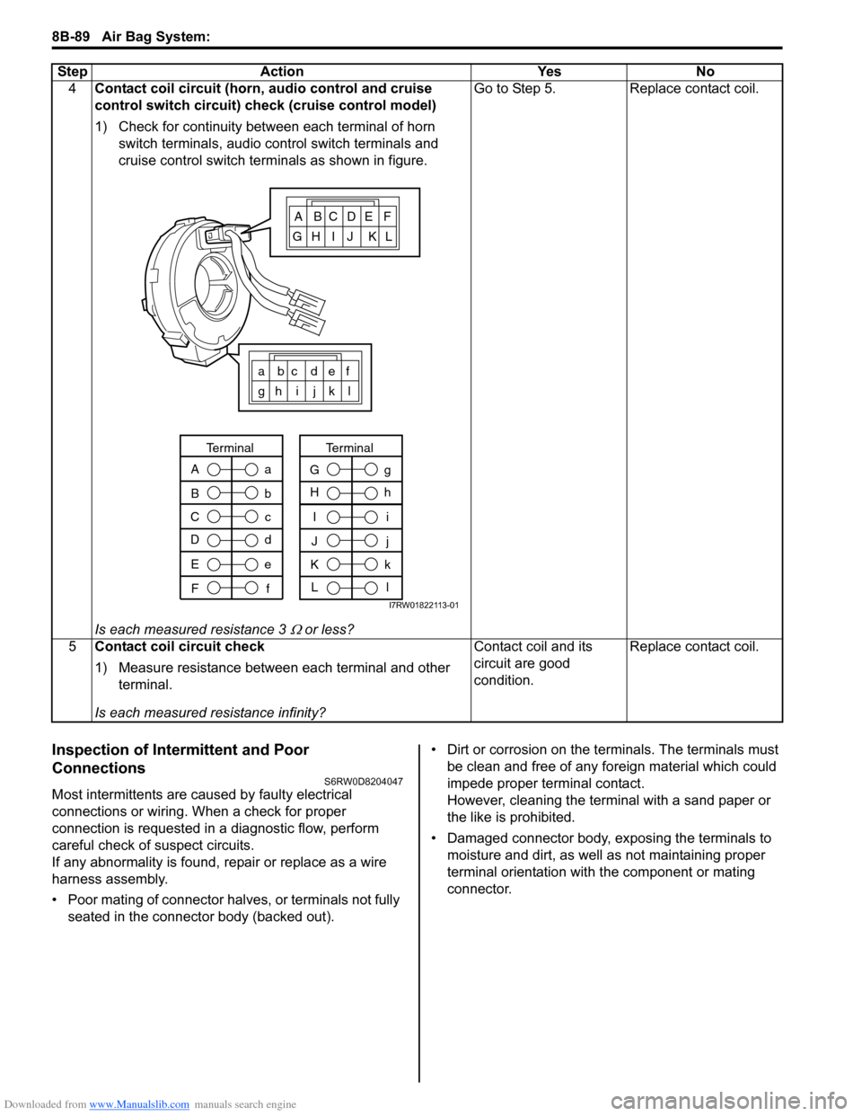
control switch circuit) check (cruise control model)
1) Check for continuity between each terminal of horn
switch terminals, audio control switch terminals and
cruise control switch terminals as shown in figure.
Is each measured resistance 3
Ω or less?Go to Step 5. Replace contact coil.
5Contact coil circuit check
1) Measure resistance between each terminal and other
terminal.
Is each measured resistance infinity?Contact coil and its
circuit are good
condition.Replace contact coil. Step Action Yes No
ABCDEF
GH I J KL
a bc def
gh i j k l
A
B
C
Da
b
c
d
Terminal
E
Fe
f
I
J
K
Li
j
k
l
Terminal
G
Hg
h
I7RW01822113-01