Page 494 of 1556
Downloaded from www.Manualslib.com manuals search engine 3A-15 Drive Shaft / Axle: Rear
Rear
General Description
Rear Drive Shaft ConstructionS6RW0D3121001
Refer to “Front Drive Shaft Construction”.
Repair Instructions
Rear Drive Shaft ComponentsS6RW0D3126001
I5RW0A312001-01
1. Differential side joint (Constant velocity DOJ joint)
: Apply dark gray grease included in spare part to
joint.6. Wheel side joint (Constant velocity ball joint)
: Apply black grease included in spare part to
joint.11. Boot (wheel side)
2. Snap ring 7. Cage : 175 N⋅m (17.5 kgf-m, 126.5 lb-ft)
3. Boot band (Large) 8. Drive shaft nut
: After tightening nut, caulk nut securely.: 80 N⋅m (8.0 kgf-m, 58.0 lb-ft)
4. Boot (Differential side) 9. Rear drive shaft flange nut : Do not reuse.
5. Boot band (Small) 10. Circrip
Page 496 of 1556

Downloaded from www.Manualslib.com manuals search engine 3A-17 Drive Shaft / Axle: Rear
Reassembly
Refer to “Front Drive Shaft Disassembly and
Reassembly” note the following points which is different
from the front drive shaft is described.
• Apply grease to each joint.
Grease color
Wheel side: Black
Differential side: Dark gray
Amount
Wheel side: 50 – 70 g (1.8 – 2.5 oz)
Differential side: 70 – 90 g (2.5 – 3.2 oz)
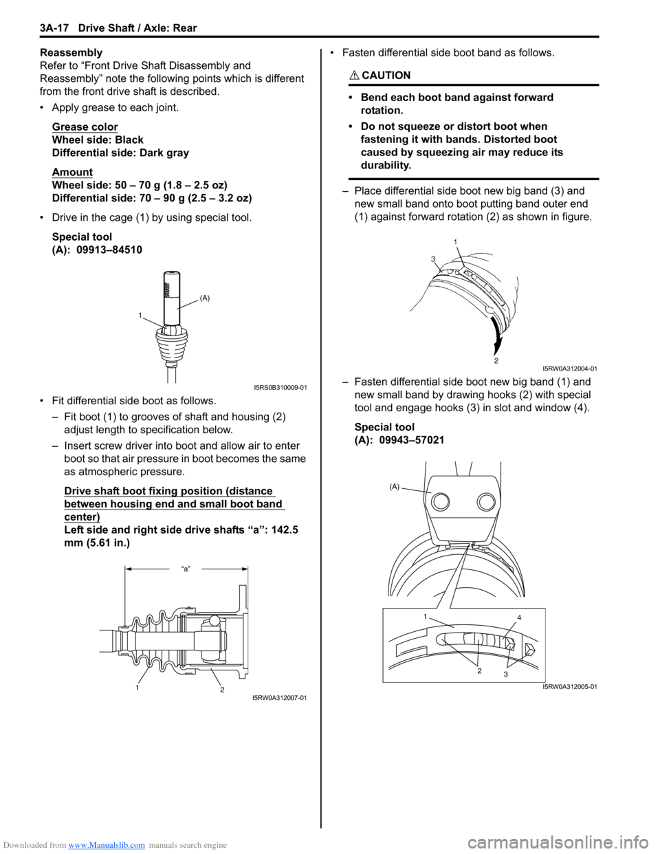
• Drive in the cage (1) by using special tool.
Special tool
(A): 09913–84510
• Fit differential side boot as follows.
– Fit boot (1) to grooves of shaft and housing (2)
adjust length to specification below.
– Insert screw driver into boot and allow air to enter
boot so that air pressure in boot becomes the same
as atmospheric pressure.
Drive shaft boot fixing position (distance
between housing end and small boot band
center)
Left side and right side drive shafts “a”: 142.5
mm (5.61 in.)• Fasten differential side boot band as follows.
CAUTION!
• Bend each boot band against forward
rotation.
• Do not squeeze or distort boot when
fastening it with bands. Distorted boot
caused by squeezing air may reduce its
durability.
– Place differential side boot new big band (3) and
new small band onto boot putting band outer end
(1) against forward rotation (2) as shown in figure.
– Fasten differential side boot new big band (1) and
new small band by drawing hooks (2) with special
tool and engage hooks (3) in slot and window (4).
Special tool
(A): 09943–57021
(A)
1
I5RS0B310009-01
“a”
2
1I5RW0A312007-01
I5RW0A312004-01
(A)
1
4
2
3
I5RW0A312005-01
Page 499 of 1556

Downloaded from www.Manualslib.com manuals search engine Differential: 3B-2
General Description
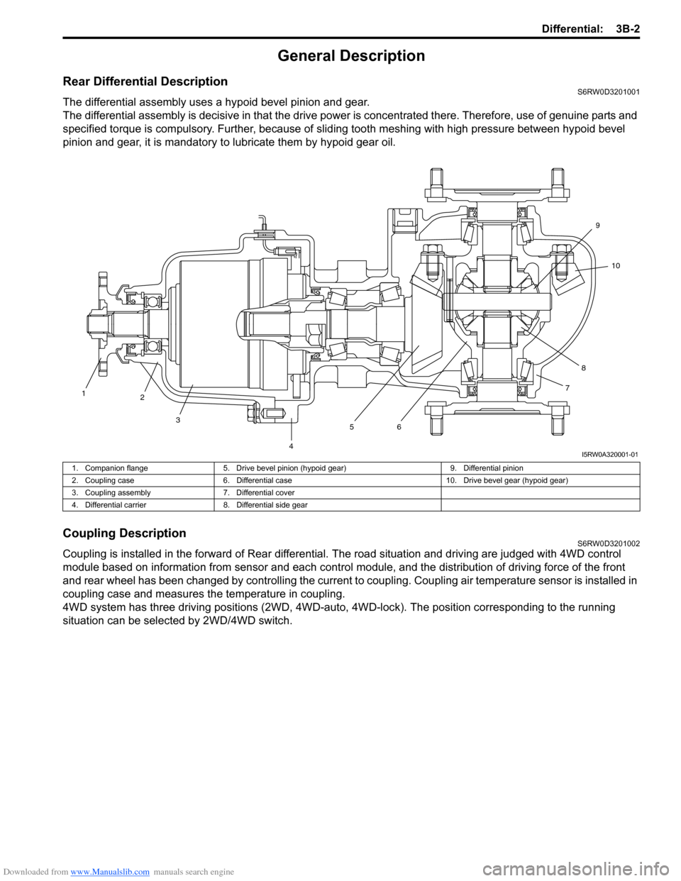
Rear Differential DescriptionS6RW0D3201001
The differential assembly uses a hypoid bevel pinion and gear.
The differential assembly is decisive in that the drive power is concentrated there. Therefore, use of genuine parts and
specified torque is compulsory. Further, because of sliding tooth meshing with high pressure between hypoid bevel
pinion and gear, it is mandatory to lubricate them by hypoid gear oil.
Coupling DescriptionS6RW0D3201002
Coupling is installed in the forward of Rear differential. The road situation and driving are judged with 4WD control
module based on information from sensor and each control module, and the distribution of driving force of the front
and rear wheel has been changed by controlling the current to coupling. Coupling air temperature sensor is installed in
coupling case and measures the temperature in coupling.
4WD system has three driving positions (2WD, 4WD-auto, 4WD-lock). The position corresponding to the running
situation can be selected by 2WD/4WD switch.
1
2
3
4567810 9
I5RW0A320001-01
1. Companion flange 5. Drive bevel pinion (hypoid gear) 9. Differential pinion
2. Coupling case 6. Differential case 10. Drive bevel gear (hypoid gear)
3. Coupling assembly 7. Differential cover
4. Differential carrier 8. Differential side gear
Page 500 of 1556
Downloaded from www.Manualslib.com manuals search engine 3B-3 Differential:
4WD Control System ComponentsS6RW0D3201003
2
1
3
6
5 4
I5RW0A320002-04
1. 4WD control module 3. 4WD LOCK indicator 5. Coupling assembly
2. 4WD AUTO indicator 4. 2WD/4WD switch 6. Coupling air temperature sensor
Page 502 of 1556

Downloaded from www.Manualslib.com manuals search engine 3B-5 Differential:
4WD Control System Wiring Circuit DiagramS6RW0D3201006
Terminal Arrangement of 4WD Control ModuleS6RW0D3201007
5V
5V
12V
G26-3
YEL
GRY
G26-2
G26-22G26-23REDWHT
G26-13
G26-14
G26-12
G26-11
G26-10BLK
WHT/RED
RED/BLK
GRY/YEL
RED/WHT
12V
L102-1
L102-4
1
37
9
10
12
13
14
12V
G26-21BLU
G26-25
G26-24ORN
BRN
5V
28
11
WHT
WHT
WHTWHTWHTWHT
WHT
RED
RED
RED
REDRED
RED
RED
46
5
L174-4BLK/ORNL174-5L174-1
I7RW01320001-01
1. Coupling assembly 6. ECM 11. Data link connector (DLC)
2. Coupling air temperature sensor 7. 4WD control module 12. “IG COIL” fuse
3. Combination meter 8. 2WD/4WD switch 13. “4WD” fuse
4. BCM 9. “4WD” switch 14. Main fuse box
5. ABS / ESP® control module 10. “4WD lock” switch
1 2 3 4 5 6 7 8 9 10 11 12
13 14 15 16 17 18 19 20 21 22 23 24 25 26
[A]
I4JA01332038-01
[A]: Connector “G26” viewed from harness side
Te r m i n a l C i r c u i t Te r m i n a l C i r c u i t
G26-2 Coupling assembly (power) G26-14 “4WD lock” switch
G26-3 Coupling assembly (ground) G26-21 Data link connector (DLC)
G26-10 Ground G26-22 CAN communication line (high)
G26-11 Power source for internal memory G26-23 CAN communication line (low)
G26-12 Power source G26-24 Coupling air temperature sensor (ground)
G26-13 “4WD” switch G26-25 Coupling air temperature sensor (power)
Page 503 of 1556

Downloaded from www.Manualslib.com manuals search engine Differential: 3B-6
Input / Output Signal Table of 4WD Control ModuleS6RW0D3201008
4WD control module outputs the following signals to coupling assembly, indicators, according to the 2WD/4WD switch
operation.
On-Board Diagnostic System DescriptionS6RW0D3201009
For 4WD control system, 4WD control module has the following functions.
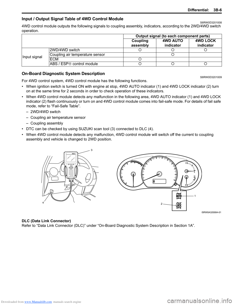
• When ignition switch is turned ON with engine at stop, 4WD AUTO indicator (1) and 4WD LOCK indicator (2) turn
on at the same time for 2 seconds in order to check operation of these indicators.
• When 4WD control module detects any malfunction in the following area, 4WD AUTO indicator (1) and 4WD LOCK
indicator (2) flash continuously or turn on and 4WD control module comes into fail-safe mode. For details of fail safe
mode, refer to “Fail-Safe Table”.
– 2WD/4WD switch
– Coupling air temperature sensor
– Coupling assembly
• DTC can be checked by using SUZUKI scan tool (3) connected to DLC (4).
• When 4WD control module detects any malfunction, 4WD control module will switch off the current to coupling
assembly and vehicle is changed to 2WD position.
DLC (Data Link Connector)
Refer to “Data Link Connector (DLC)” under “On-Board Diagnostic System Description in Section 1A”.Output signal (to each component parts)
Coupling
assembly4WD AUTO
indicator4WD LOCK
indicator
Input signal2WD/4WD switch�{�{�{
Coupling air temperature sensor�{
ECM�{
ABS / ESP® control module�{�{�{
1
2 3
4
I5RW0A320004-01
Page 505 of 1556

Downloaded from www.Manualslib.com manuals search engine Differential: 3B-8
Diagnostic Information and Procedures
4WD Control System CheckS6RW0D3204001
Refer to the following items for the details of each step.
Step Action Yes No
1�) Customer complaint analysis
1) Perform customer complaint analysis.
Was customer complaint analysis performed?Go to Step 2. Perform customer
complaint analysis.
2�) DTC check, record and clearance
1) Check for DTC.
Is there any DTC(s)?Print DTC or write them
down and clear them by
referring to “DTC
Clearance”. Go to Step
3.Go to Step 4.
3�) Visual inspection
1) Perform visual inspection.
Is there any faulty condition?Repair or replace
malfunction part. Go to
St ep 11 .Go to Step 5.
4�) Visual inspection
1) Perform visual inspection.
Is there any faulty condition?Repair or replace
malfunction part. Go to
St ep 11 .Go to Step 8.
5�) Trouble symptom confirmation
1) Select 2WD/4WD switch to “2WD”, “4WD-auto” and
“4WD-lock” positions referring to “4WD Control System
Operation Inspection”.
2) Confirm trouble symptom.
Is trouble symptom identified?Go to Step 6. Go to Step 7.
6�) Rechecking and record of DTC
1) Recheck for DTC referring to “DTC Check”.
Is there any DTC(s)?Go to Step 9. Go to Step 8.
7�) Rechecking and record of DTC
1) Recheck for DTC referring to “DTC Check”.
Is there any DTC(s)?Go to Step 9. Go to Step 10.
8�) 4WD control symptom diagnosis
1) Check and repair according to “4WD Control Symptom
Diagnosis”.
Are check and repair complete?Go to Step 11. Check and repair
malfunction part(s). Go
to Step 11.
9�) Troubleshooting for DTC
1) Check and repair according to applicable DTC flow.
Are check and repair complete?Go to Step 11. Check and repair
malfunction part(s). Go
to Step 11.
10�) Check for intermittent problems
1) Check for intermittent problems referring to “Intermittent
and Poor Connection Inspection in Section 00”.
Is there any faulty condition?Repair or replace
malfunction part(s). Go
to Step 11.Go to Step 11.
11�) Final confirmation test
1) Clear DTC if any.
2) Perform final confirmation test.
Is there any problem symptom, DTC or abnormal condition?Go to Step 6. END.
Page 506 of 1556

Downloaded from www.Manualslib.com manuals search engine 3B-9 Differential:
Detail of 4WD Control System Check
Step 1. Customer complaint analysis
Record details of the problem (failure, complaint) and how it occurred as described by the customer.
For this purpose, use of such a questionnaire form as shown in the following will facilitate collecting information to the
point required for proper analysis and diagnosis.
Customer questionnaire (Example)
NOTE
The form is a standard sample. It should be modified according to conditions characteristic of each
market.
Customer’s name: Model: VIN:
Problem Symptoms
Frequency of Occurrence
Conditions for
Occurrence of Problem
Environmental Condition
Diagnostic Trouble Code
Date of Reg:
4WD position indicator abnormal: fails to turn on / fails to turn off /
flashes
Abnormal noise while vehicle running: from coupling assembly
other
No changed to “2WD” position
No changed to “4WD-lock” position
No changed to “4WD-auto” position
When starting: at initial start only / at every start / other
Vehicle speed: while accelerating / while decelerating / at stop /
while turning / while running at constant speed /
other
Road surface condition: Paved road / rough road / snow-covered road /
other
Wheather: fine / cloudy / rain / snow / other
Temperature: ( )
First check: Normal code / malfunction code ( )
Second check after test drive: Normal code / malfunction code ( ) Continuous / Intermittent ( times a day, a month) /
otherDate of problem: Mileage: Date of issue:
I5RW0A320007-02