Page 1274 of 1556
Downloaded from www.Manualslib.com manuals search engine 9A-107 Wiring Systems:
GEAR
ABS
BELT
DOOR
CHARGE
CHECK ENGINEAIRBAG
OILDRLD/F LOCK4WD AUTO
SETCRUISEIMMOBI
BRAKE
FUEL
DOME
15A37
32 5
WHT/RED
WHT/RED
J/B
G271
G241
1
2
J/C
G308B
B
IF EQPD
I6RW0C910976-01
Page 1298 of 1556
Downloaded from www.Manualslib.com manuals search engine 9A-131 Wiring Systems:
F-1 Air-Bag System Circuit Diagram (4ch)S6RW0D910E032
2
ORN
Y
A/B
SDM
L04
J/B
15AA/B
27
RED
L313
BCM
15
BLK
1
15ADOME
37
WHT/RED
G2715
E388
L3721G349
L3992
PNK/BLK
E40
Forward sensor
1 2
Contact
coil
G347
S172
L377
G3442L399
G34911
L28312S121
YEL/RED
GRN
12
21
YEL/RED
L285 G25912
4
38
75
69
10 2832 27
37
5051
2
"A-8"
L378
G345
ORN
PNK/BLKYEL
YEL
GRN/RED
GRN/REDGRNGRN/ORNGRN/YEL
BLU/RED
BLU/REDBLU/ORNBLU/YEL
L3134
G27213
J/B J/B
"C-3"YB
YEL/BLK
YEL/BLK
J/B side connector (BCM)
Except M16A engine M/T
M16A engine M/T
Except Taiwan
Taiwan A
B
E
D
2 12 1
BCDE
Check terminal
J/C
G308B
B
5
4
C
51114
E382
G33419
C343
E3718
BLK/ORN
BLK/ORNBLK/ORN
7
BLU
PPL/WHT
PPL/WHT
BLU
PPL/WHT
J/C IF EQPD
G308A
A
L313
G043
5
J/CJ/B
G309B
B
DLC
16
WHT
WHT/RED
RED
RW
PW
PW
"A-8"
14 6
BCM
BCM
(CAN)
G2114
BLKBLK
BLK
E
Y"A-8"
D
8A
I6RW0C910A00-01
Page 1299 of 1556
Downloaded from www.Manualslib.com manuals search engine Wiring Systems: 9A-132
F-1 Air-Bag System Circuit Diagram (8ch)S6RW0D910E033
Y
A/B
SDM
L04
J/B
15AA/B
27
REDWHT/RED
L313
BCM
15
BLK
1
15ADOME
37
G2715
2
2832 2737
"A-8"
YEL
YEL
G349
L399
J/C
G308B
B
L399
G3491
5
41114
E382
G33419
C343
E3718
BLK/ORNWHT/RED
BLK/ORNBLK/ORN
7
BLU
PPL/WHT
PPL/WHT
J/C IF EQPD
G308A
A
J/C
G309B
B
DLC
16
WHTRED
RW
PW
"A-8"
14 6
BCM
(CAN)
G2114
BLKBLK
BLK
J/B
E
Y"A-8"
D
B
5
C
D
E
J/B side connector (BCM)
Except M16A engine M/T
M16A engine M/T
Except Taiwan
Taiwan
Without Auto cruise
With Auto cruise ABCDEFG
Contact
coil
G347
S172
L377
G34421
S121
GRN
4
3
GRN/RED
GRN/REDGRN
1
2FG2
1FG
1
2FG2
1FG
BLU
PPL/WHTL313
G043
5
J/B
PW
BCM
8A
G25912
21
5
6
L378
G345
BLU/RED
BLU/RED
YEL/RED
YEL/RED
I6RW0C910A01-01
Page 1320 of 1556
Downloaded from www.Manualslib.com manuals search engine 9B-1 Lighting Systems:
Body, Cab and Accessories
Lighting Systems
Precautions
Precautions for Discharge Headlight Service (If Equipped)S6RW0D9200001
WARNING!
• Do not touch igniter or ballast when lighting switch is at “HEAD” position to avoid possible electric
shock.
• Do not measure voltage or resistance with tester connected to output connector of ballast or igniter
to avoid possible electric shock.
• Do not perform work where exposed to water including rain or with wet hands to avoid possible
electric shock.
• Disassembling igniter or ballast is strictly prohibited as it may cause an electric shock.
• Before inspecting or repairing discharge headlight or its peripheral parts, make sure that lighting
switch is at OFF position and battery is disconnected at negative terminal to avoid possible
electrical shock.
• Do not set lighting switch to “HEAD” position with connector disconnected or any part removed to
avoid possible electric shock.
• Do not touch glass surface of headlight bulb. Oil or grease attached on it may not only make bulb
service life shorter but also cause bulb to burst when lighting switch is turned on.
• Mercury, metal iodide and xenon gas are sealed in discharge headlight bulb. Be sure to dispose of
used discharge headlight bulb properly according to applicable rules or regulations.
Precautions in Diagnosing Troubles (Headlight Auto Leveling System)S6RW0D9200002
• Be sure to read “Air Bag Warning in Section 00” before inspection and observe what is written there.
• Replacement of height sensor and headlight leveling control module. When height sensor and/or headlight leveling
control module is replaced with new one, perform initialization of headlight auto leveling system according to
“Initialization of Headlight Auto Leveling System”.
General Description
Discharge Headlight Description (If Equipped)S6RW0D9201001
Discharge headlight provides more brightness and consumes less electricity as compared with the conventional
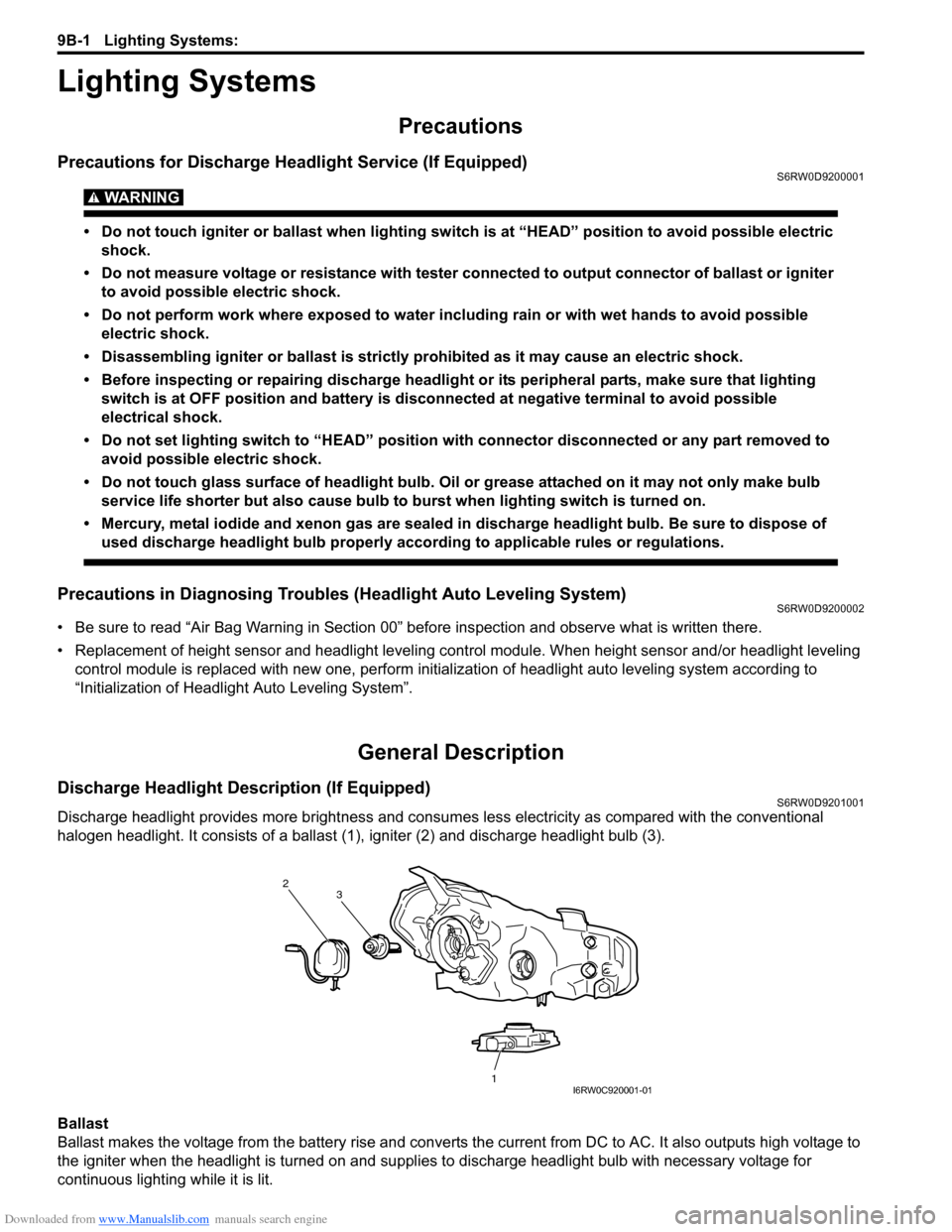
halogen headlight. It consists of a ballast (1), igniter (2) and discharge headlight bulb (3).
Ballast
Ballast makes the voltage from the battery rise and converts the current from DC to AC. It also outputs high voltage to
the igniter when the headlight is turned on and supplies to discharge headlight bulb with necessary voltage for
continuous lighting while it is lit.
2
1 3
I6RW0C920001-01
Page 1353 of 1556
Downloaded from www.Manualslib.com manuals search engine Instrumentation / Driver Info. / Horn: 9C-1
Body, Cab and Accessories
Instrumentation / Driver Info. / Horn
Precautions
Precautions in Diagnosing Troubles for Combination MeterS6RW0D9300001
Combination meter uses signals (information) from each control module by CAN communication to control
speedometer, tachometer, fuel meter, engine coolant temp meter, warning light and indicator light (other than air bag
warning light, EPS warning light, headlight leveling warning light (if equipped), rear fog light indicator light (if
equipped), high beam indicator light and turn signal indicator light). Therefor, check that no DTC is detected in each
module before performing combination meter symptom diagnosis. If any DTC is detected, correct trouble indicated by
that DTC troubleshooting first.
General Description
CAN Communication System DescriptionS6RW0D9301001
Refer to “CAN Communication System Description in Section 1A” for CAN communication system description.
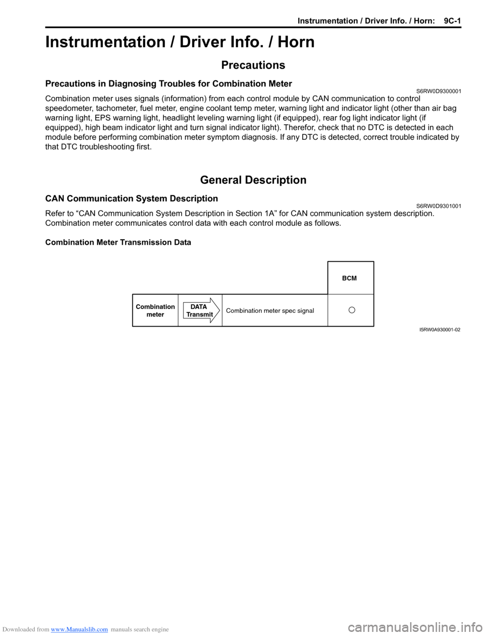
Combination meter communicates control data with each control module as follows.
Combination Meter Transmission Data
BCM
Combination
meterDATA
TransmitCombination meter spec signal
I5RW0A930001-02
Page 1357 of 1556
Downloaded from www.Manualslib.com manuals search engine Instrumentation / Driver Info. / Horn: 9C-5
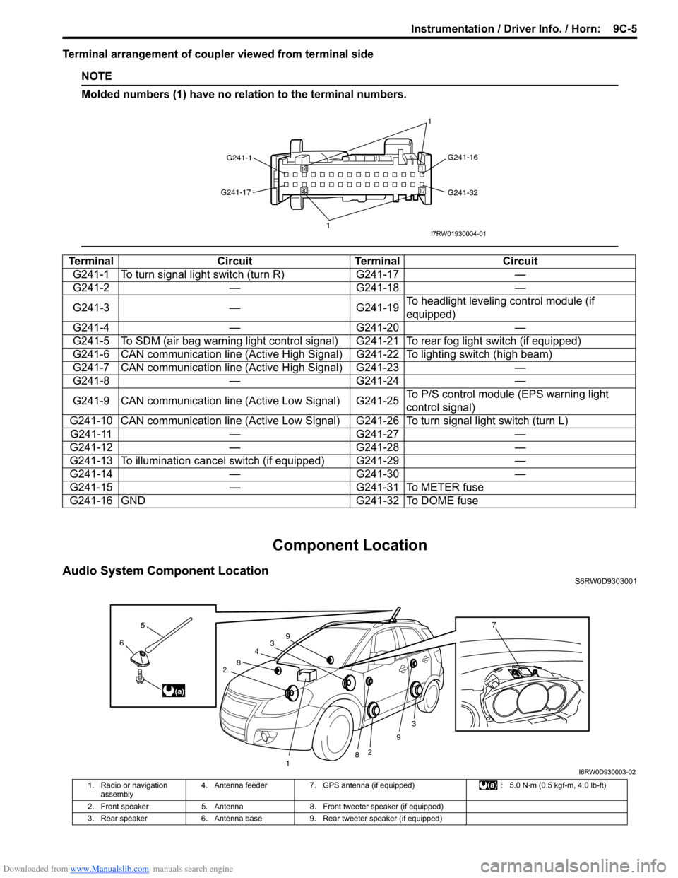
Terminal arrangement of coupler viewed from terminal side
NOTE
Molded numbers (1) have no relation to the terminal numbers.
Component Location
Audio System Component LocationS6RW0D9303001
Terminal Circuit Terminal Circuit
G241-1 To turn signal light switch (turn R) G241-17 —
G241-2 — G241-18 —
G241-3 — G241-19To headlight leveling control module (if
equipped)
G241-4 — G241-20 —
G241-5 To SDM (air bag warning light control signal) G241-21 To rear fog light switch (if equipped)
G241-6 CAN communication line (Active High Signal) G241-22 To lighting switch (high beam)
G241-7 CAN communication line (Active High Signal) G241-23 —
G241-8 — G241-24 —
G241-9 CAN communication line (Active Low Signal) G241-25To P/S control module (EPS warning light
control signal)
G241-10 CAN communication line (Active Low Signal) G241-26 To turn signal light switch (turn L)
G241-11 — G241-27 —
G241-12 — G241-28 —
G241-13 To illumination cancel switch (if equipped) G241-29 —
G241-14 — G241-30 —
G241-15 — G241-31 To METER fuse
G241-16 GND G241-32 To DOME fuse
G241-1G241-16
G241-32 G241-17
11I7RW01930004-01
3
2
3
2
1
4
8
8
9
96
5
(a)
7
I6RW0D930003-02
1. Radio or navigation
assembly4. Antenna feeder 7. GPS antenna (if equipped) : 5.0 N⋅m (0.5 kgf-m, 4.0 lb-ft)
2. Front speaker 5. Antenna 8. Front tweeter speaker (if equipped)
3. Rear speaker 6. Antenna base 9. Rear tweeter speaker (if equipped)
Page 1369 of 1556
Downloaded from www.Manualslib.com manuals search engine Instrumentation / Driver Info. / Horn: 9C-17
Outside Air Temperature Sensor Removal and
Installation (If Equipped)
S6RW0D9306013
Removal
1) Disconnect negative (–) cable at battery.
2) Remove front bumper referring to “Front Bumper
and Rear Bumper Components in Section 9K”.
3) Disconnect connector from outside air temperature
sensor.
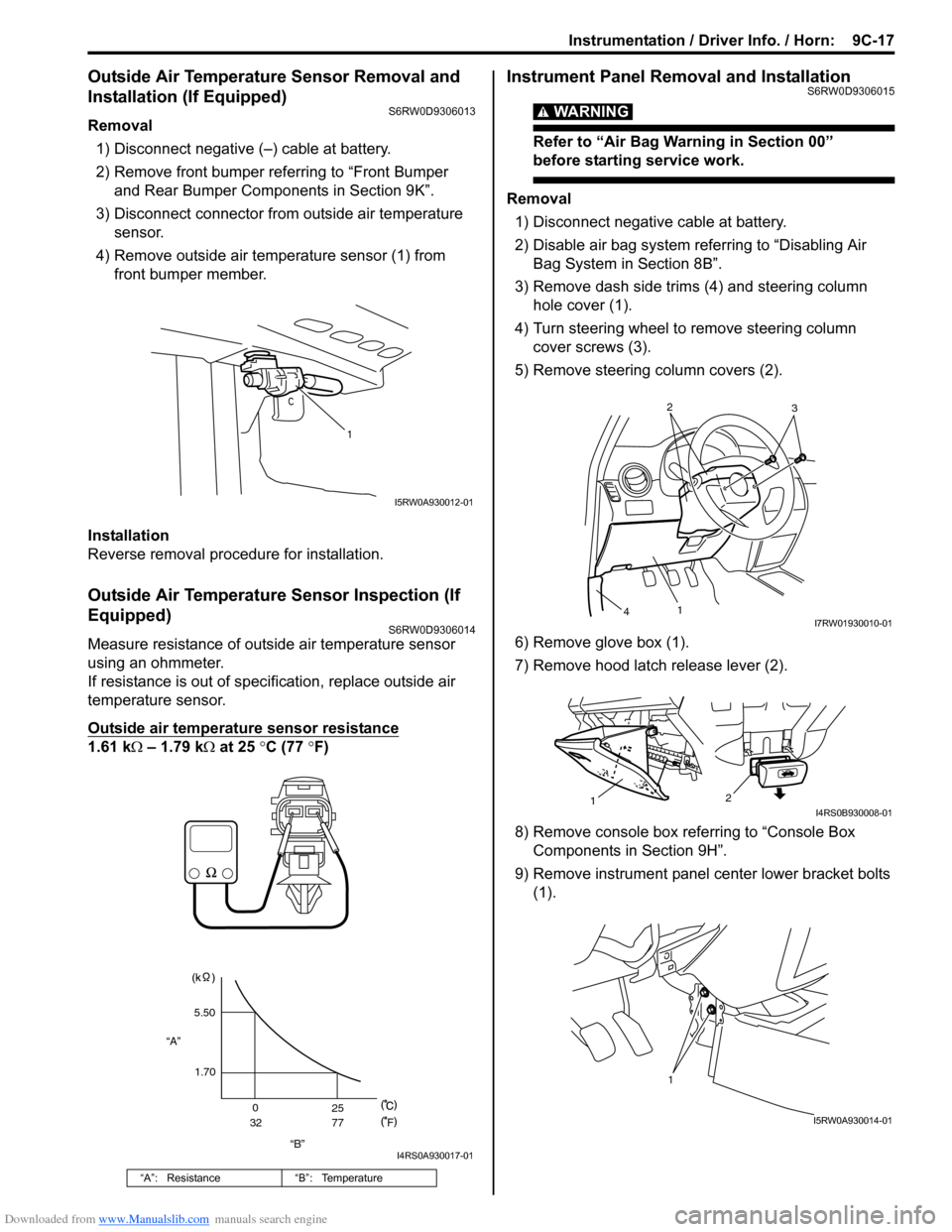
4) Remove outside air temperature sensor (1) from
front bumper member.
Installation
Reverse removal procedure for installation.
Outside Air Temperature Sensor Inspection (If
Equipped)
S6RW0D9306014
Measure resistance of outside air temperature sensor
using an ohmmeter.
If resistance is out of specification, replace outside air
temperature sensor.
Outside air temperature sensor resistance
1.61 kΩ – 1.79 kΩ at 25 °C (77 °F)
Instrument Panel Removal and InstallationS6RW0D9306015
WARNING!
Refer to “Air Bag Warning in Section 00”
before starting service work.
Removal
1) Disconnect negative cable at battery.
2) Disable air bag system referring to “Disabling Air
Bag System in Section 8B”.
3) Remove dash side trims (4) and steering column
hole cover (1).
4) Turn steering wheel to remove steering column
cover screws (3).
5) Remove steering column covers (2).
6) Remove glove box (1).
7) Remove hood latch release lever (2).
8) Remove console box referring to “Console Box
Components in Section 9H”.
9) Remove instrument panel center lower bracket bolts
(1).
“A”: Resistance “B”: Temperature
1
I5RW0A930012-01
“B” “A”5.50
1.70
0
3225
77
F
I4RS0A930017-01
2
3
1
4I7RW01930010-01
2
1I4RS0B930008-01
1
I5RW0A930014-01
Page 1370 of 1556
Downloaded from www.Manualslib.com manuals search engine 9C-18 Instrumentation / Driver Info. / Horn:
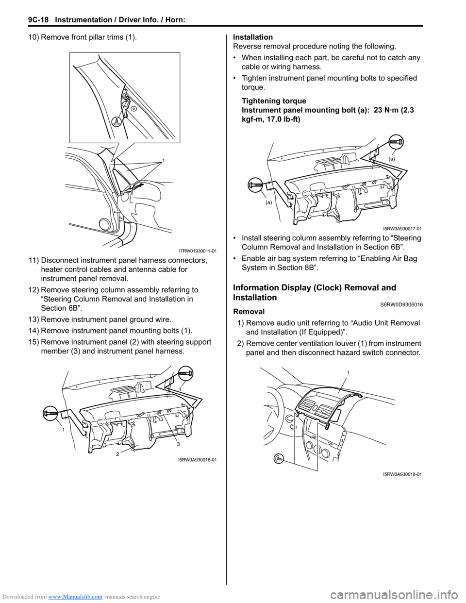
10) Remove front pillar trims (1).
11) Disconnect instrument panel harness connectors,
heater control cables and antenna cable for
instrument panel removal.
12) Remove steering column assembly referring to
“Steering Column Removal and Installation in
Section 6B”.
13) Remove instrument panel ground wire.
14) Remove instrument panel mounting bolts (1).
15) Remove instrument panel (2) with steering support
member (3) and instrument panel harness.Installation
Reverse removal procedure noting the following.
• When installing each part, be careful not to catch any
cable or wiring harness.
• Tighten instrument panel mounting bolts to specified
torque.
Tightening torque
Instrument panel mounting bolt (a): 23 N·m (2.3
kgf-m, 17.0 lb-ft)
• Install steering column assembly referring to “Steering
Column Removal and Installation in Section 6B”.
• Enable air bag system referring to “Enabling Air Bag
System in Section 8B”.
Information Display (Clock) Removal and
Installation
S6RW0D9306016
Removal
1) Remove audio unit referring to “Audio Unit Removal
and Installation (If Equipped)”.
2) Remove center ventilation louver (1) from instrument
panel and then disconnect hazard switch connector.
1
I7RW01930011-01
11
3
2I5RW0A930016-01
(a)
(a)
I5RW0A930017-01
1
I5RW0A930018-01


