Page 1250 of 1556

Downloaded from www.Manualslib.com manuals search engine 9A-83 Wiring Systems:
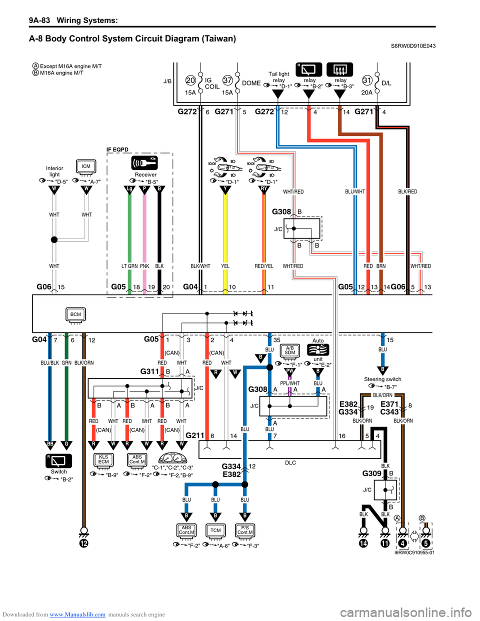
A-8 Body Control System Circuit Diagram (Taiwan)S6RW0D910E043
1G053
WHTRED
2
G211
4
6
14
WHTRED
PNKLT GRN
G05
DLC
4
111412
BLK
BLKBLK
B
B
J/C
G309
18
BLK/WHT
G041
WHT/RED
13
1920
Receiver
35
BLU
15
BLU
BLUBLU
BLUBLU
BLU
WHTWHT
"F-2""F-3"
P/S
Cont.MABS
Cont.M
"B-9"
KLS
ECM
"A-7"
ICM
RW
B
BB
E382
G334E371
C34319
G334
E38212
8
BLK/ORN
5
4
J/B
15ADOME
37
20AD/L
31
15AIG
COIL
20
G271 G2715G27212
BLK/RED
5 4
G2726
WHT/RED
WHT/RED
BLK/ORN
716
B
B
B
J/C
G308
BLK/ORN
A
AA
J/C
G308
B
BA
A
WHTREDWHTRED
RW
BA
J/C
G311
"F-2,"B-9" "C-1","C-2","C-3""B-2" Switch
7G04612
GRNBLU/BLKBLK/ORN
BB
"B-7" Steering switch unit Auto
"E-2""F-1"BB
PPL/WHTA
PW
G
BPLg
WHT
G06G06
BLU/WHT
12 4
RED
13 14
BRN
14G0515
WW"B-5"
Interior
light
"D-5"
Tail light
relay
"D-1"
RW
BCM
BLK
BLU
"A-6"
TCM
B
(CAN)
(CAN) (CAN)
"F-2"
ABS
Cont.M
A/B
SDM
WHTRED
RW
BA
(CAN)(CAN) IF EQPD
"D-1"
YEL
1011
relay
"B-2"
RYY
RED/YEL
"D-1"
relay
"B-3"
Except M16A engine M/T
M16A engine M/T A
A
5
B
B
I6RW0C910955-01
Page 1274 of 1556
Downloaded from www.Manualslib.com manuals search engine 9A-107 Wiring Systems:
GEAR
ABS
BELT
DOOR
CHARGE
CHECK ENGINEAIRBAG
OILDRLD/F LOCK4WD AUTO
SETCRUISEIMMOBI
BRAKE
FUEL
DOME
15A37
32 5
WHT/RED
WHT/RED
J/B
G271
G241
1
2
J/C
G308B
B
IF EQPD
I6RW0C910976-01
Page 1290 of 1556
Downloaded from www.Manualslib.com manuals search engine 9A-123 Wiring Systems:
D-7 Brake Light System Circuit DiagramS6RW0D910E028
Brake
light
switch
Shift lock
relay
(R)
Brake light
GRNLT GRN/BLK
BLK
(L)
E181
L134
GRN/WHT
GRN/WHT
GRN/WHTGRN/WHT
5
L315
E325
J/B
"F-2"
ABS
Cont.M
GRN/WHT
2 2 1
"A-5"
ECM
21
GW
GW
GRN/YEL
"A-5"
ECM
GY
GW
42
31
J/B
L1332
52
1
GRN/WHT
"A-6"
GW
O92
High mounted
stop light
201918
BLKBLK
BLKBLKBLK
23
BLK
BLK
2
GRN/WHTGRN/WHTGRN/WHT
E3232
L393
L2331
O233
L3932
L390
O2312 15A
30STOP
E32512 10A
26IG1 SIG
Cruise control
(IF EQPD)
I6RW0C910A15-01
Page 1301 of 1556
Downloaded from www.Manualslib.com manuals search engine Wiring Systems: 9A-134
F-2 Anti-Lock Brake System Circuit DiagramS6RW0D910E034
2326
24
25
72
13E08
BLK
30A
ABS
SOL
40A
ABS
MOT11
WHT/REDWHT/BLU
GRN/WHT
8
BLK
R
RED
W
WHT
REDWHT
REDWHT
"A-8"
"A-5"
J/B10AABS
28
E3259
GRN/ORN
9
L315
L338
3
2
GRN/YEL
GRN/ORN
6
GW"D-7"
Brake light
switch
Individual circuit
fuse box (No.1)
1
GRN/BLK
GRN/YEL
3
G sensor
L371
E38715
G333
E38112
14
RED
R
112
WHT
W
B
BG311
A
A
RW
J/C
(CAN)(CAN)
Taiwan
(CAN)
9
IF EQPD
GRN/BLK
ABS
Cont.M
BCM
ECM
I6RW0C910A03-01
Page 1302 of 1556
Downloaded from www.Manualslib.com manuals search engine 9A-135 Wiring Systems:
A
YEL
ABS
Cont.M
L32
LT GRN/BLKLT GRN
LT GRN/BLKLT GRN
L371
E38728
Wheel speed
sensor
(RL)
BRN
YELBRN
7
1
L31
Wheel speed
sensor
(RR)
WHT/BLK
E33
Wheel speed
sensor
(FR)
WHTRED
E35
Wheel speed
sensor
(FL)
RED/BLK
181711
2219
2021
10E08
121 21 21 2
16
DLC
E382
G334
5
BLU
BLU
BLU
WHT/RED
G211
B
WHTRED
RW
BCM
"A-8"
11
BLK
BLK
14
BLK
B
B
J/C
G309
4
E371
C3438
E382
G33412
BLK/ORN
BLK/ORN
B
B
J/C
G308
15ADOME
37
G2715
WHT/RED
J/B
BLK/ORN
14
67
16 19
A
A
J/C
IF EQPDTaiwan Except Taiwan
G308
9
5E04
G04
4
B
5
(CAN)
BCM
Except M16A engine M/T
M16A engine M/T AB
I6RW0C910A04-01
Page 1354 of 1556

Downloaded from www.Manualslib.com manuals search engine 9C-2 Instrumentation / Driver Info. / Horn:
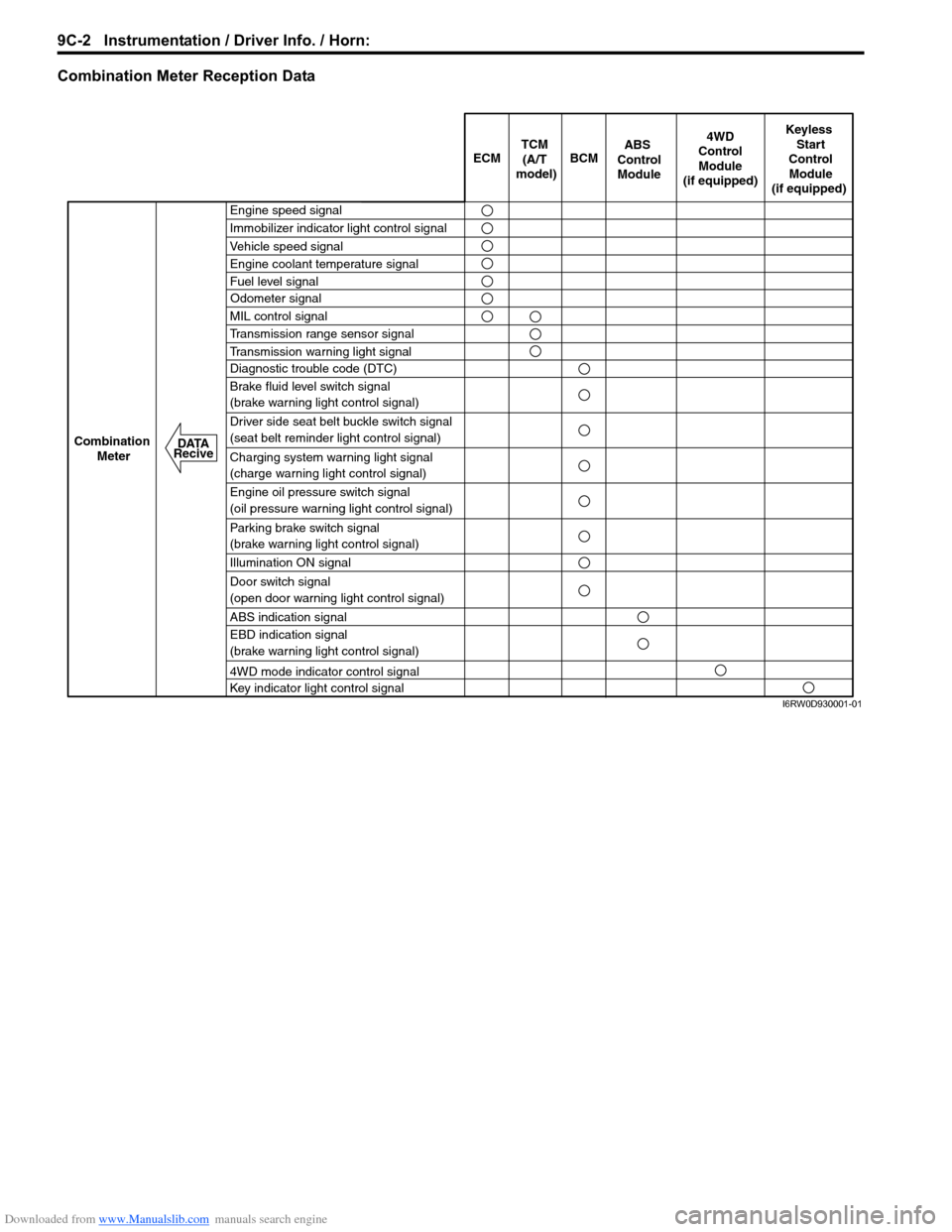
Combination Meter Reception Data
ECM BCM
Keyless
Start
Control
Module
(if equipped)
Combination
Meter4WD
Control
Module
(if equipped)TCM
(A/T
model)
Engine speed signal
Immobilizer indicator light control signal
Vehicle speed signal
Engine coolant temperature signal
Fuel level signal
MIL control signal
Transmission range sensor signal
Transmission warning light signal
Diagnostic trouble code (DTC)
Brake fluid level switch signal
(brake warning light control signal)
Driver side seat belt buckle switch signal
(seat belt reminder light control signal)
Charging system warning light signal
(charge warning light control signal)
Engine oil pressure switch signal
(oil pressure warning light control signal)
Parking brake switch signal
(brake warning light control signal)
Illumination ON signal
Door switch signal
(open door warning light control signal)
ABS indication signal
EBD indication signal
(brake warning light control signal)
4WD mode indicator control signal
Key indicator light control signal
ABS
Control
Module
Odometer signal
DATA
Recive
I6RW0D930001-01
Page 1360 of 1556

Downloaded from www.Manualslib.com manuals search engine 9C-8 Instrumentation / Driver Info. / Horn:
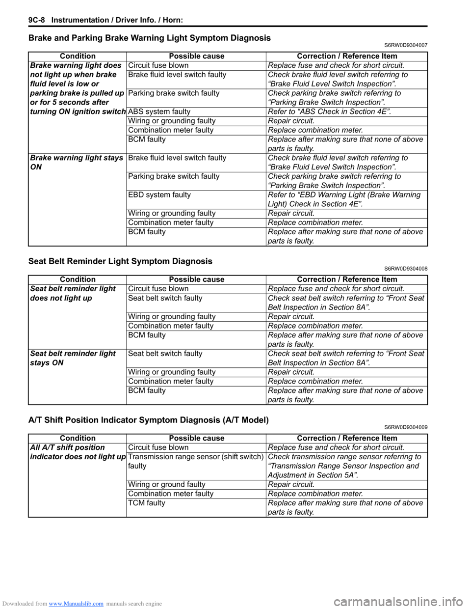
Brake and Parking Brake Warning Light Symptom DiagnosisS6RW0D9304007
Seat Belt Reminder Light Symptom DiagnosisS6RW0D9304008
A/T Shift Position Indicator Symptom Diagnosis (A/T Model)S6RW0D9304009
Condition Possible cause Correction / Reference Item
Brake warning light does
not light up when brake
fluid level is low or
parking brake is pulled up
or for 5 seconds after
turning ON ignition switchCircuit fuse blownReplace fuse and check for short circuit.
Brake fluid level switch faultyCheck brake fluid level switch referring to
“Brake Fluid Level Switch Inspection”.
Parking brake switch faultyCheck parking brake switch referring to
“Parking Brake Switch Inspection”.
ABS system faultyRefer to “ABS Check in Section 4E”.
Wiring or grounding faultyRepair circuit.
Combination meter faultyReplace combination meter.
BCM faultyReplace after making sure that none of above
parts is faulty.
Brake warning light stays
ONBrake fluid level switch faultyCheck brake fluid level switch referring to
“Brake Fluid Level Switch Inspection”.
Parking brake switch faultyCheck parking brake switch referring to
“Parking Brake Switch Inspection”.
EBD system faultyRefer to “EBD Warning Light (Brake Warning
Light) Check in Section 4E”.
Wiring or grounding faultyRepair circuit.
Combination meter faultyReplace combination meter.
BCM faultyReplace after making sure that none of above
parts is faulty.
Condition Possible cause Correction / Reference Item
Seat belt reminder light
does not light upCircuit fuse blownReplace fuse and check for short circuit.
Seat belt switch faultyCheck seat belt switch referring to “Front Seat
Belt Inspection in Section 8A”.
Wiring or grounding faultyRepair circuit.
Combination meter faultyReplace combination meter.
BCM faultyReplace after making sure that none of above
parts is faulty.
Seat belt reminder light
stays ONSeat belt switch faultyCheck seat belt switch referring to “Front Seat
Belt Inspection in Section 8A”.
Wiring or grounding faultyRepair circuit.
Combination meter faultyReplace combination meter.
BCM faultyReplace after making sure that none of above
parts is faulty.
Condition Possible cause Correction / Reference Item
All A/T shift position
indicator does not light upCircuit fuse blownReplace fuse and check for short circuit.
Transmission range sensor (shift switch)
faultyCheck transmission range sensor referring to
“Transmission Range Sensor Inspection and
Adjustment in Section 5A”.
Wiring or ground faultyRepair circuit.
Combination meter faultyReplace combination meter.
TCM faultyReplace after making sure that none of above
parts is faulty.
Page 1455 of 1556

Downloaded from www.Manualslib.com manuals search engine Paint / Coatings: 9L-1
Body, Cab and Accessories
Paint / Coatings
General Description
Anti-Corrosion Treatment ConstructionS6RW0D9C01001
WARNING!
Standard shop practices, particularly eye protection, should be followed during the performance of the
following operations to avoid personal injury.
As rust proof treatment, steel sheets are given corrosion resistance on the interior and/or exterior.
These corrosion resistance steel sheet materials are called one of two-side galvanized steel sheets.
It is for the sake of rust protection that these materials are selected and given a variety of treatments as described
blow.
• Steel sheets are treated with cathodic electro primer which is excellent in corrosion resistance.
• Rust proof wax coatings are applied to door and side sill insides where moisture is liable to stay.
• Vinyl coating is applied to body underside and wheel housing inside.
• Sealer is applied to door hem, engine compartment steel sheet-to-steel sheet joint, and the like portions to prevent
water penetration and resulting in rust occurrence.
In panel replacement or collision damage repair, leaving the relevant area untreated as it is in any operation which
does disturb the rust proof treatment will cause corrosion to that area. Therefore, it is the essential function of any
repair operation to correctly recoat the related surfaces of the relevant area.
All the metal panels are coated with metal conditioners and primer coating during vehicle production. Following the
repair and/or replacement parts installation, every accessible bare metal surface should be cleaned and coated with
rust proof primer. Perform this operation prior to the application of sealer and rust proof wax coating.
Sealer is applied to the specific joints of a vehicle during production. The sealer is intended to prevent dust from
entering the vehicle and serves also as an anticorrosion barrier. The sealer is applied to the door and hood hem areas
and between panels. Correct and reseal the originally sealed joints if damaged. Reseal the attaching joints of a new
replacement panel and reseal the hem area of a replacement door or hood.
Use a quality sealer to seal the flanged joints, overlap joints and seams. The sealer must have flexible characteristics
and paint ability after it’s applied to repair areas.
For the sealer to fill open joints, use caulking material. Select a sealer in conformance with the place and purpose of a
specific use. Observe the manufacturer’s label-stand instructions when using the sealer.
In many cases, repaired places require color painting. When this is required, follow the ordinary techniques specified
for the finish preparation, color painting and undercoating build-up.
Rust proof wax, a penetrative compound, is applied to the metal-to-metal surfaces (door and side sill insides) where it
is difficult to use ordinary undercoating material for coating. Therefore, when selecting the rust proof wax, it may be the
penetrative type.
During the undercoating (vinyl coating) application, care should be taken that sealer is not applied to the engine-
related parts and shock absorber mounting or rotating parts. Following the under coating, make sure that body drain
holes are kept open.
The sequence of the application steps of the anti-corrosion materials are as follows:
1) Clean and prepare the metal surface.
2) Apply primer.
3) Apply sealer (all joints sealed originally).
4) Apply color in areas where color is required such as hem flanges, exposed joints and under body components.
5) Apply anticorrosion compound (penetrative wax).
6) Apply undercoating (rust proof material).