2006 SUZUKI SX4 u0121
[x] Cancel search: u0121Page 524 of 1556

Downloaded from www.Manualslib.com manuals search engine 3B-27 Differential:
DTC U0073: Control Module Communication Bus OffS6RW0D3204022
Refer to “Troubleshooting for CAN-DTC in Section 1A”.
DTC U0100: Lost Communication with ECMS6RW0D3204023
Refer to “Troubleshooting for CAN-DTC in Section 1A”.
DTC U0121: Lost Communication with ABS / ESP® Control ModuleS6RW0D3204024
Refer to “Troubleshooting for CAN-DTC in Section 1A”.
DTC U0155: Lost Communication with Instrument Panel Cluster (IPC) Control ModuleS6RW0D3204025
Refer to “Troubleshooting for CAN-DTC in Section 1A”.
Inspection of 4WD Control Module and Its CircuitsS6RW0D3204026
4WD control module and its circuits can be checked at coupler connected to 4WD control module by measuring
voltage, pulse signal.
CAUTION!
4WD control module cannot be checked by itself. It is strictly prohibited to connect voltmeter or
ohmmeter to 4WD control module with couplers disconnected from it.
Voltage and Signal Check
1) Check voltage using voltmeter (1) connected to each terminal of couplers.
2) Check signal using oscilloscope (2) connected to each terminal of couplers.
NOTE
• As each terminal voltage is affected by the battery voltage, confirm that it is 11 V or more when
ignition switch is turned ON.
• Pulse signal cannot be measured by voltmeter. It can be measured by oscilloscope.
• Item with asterisk (*) in normal voltage column can be read only by oscilloscope.
12
I4JA01332053-01
Page 1511 of 1556

Downloaded from www.Manualslib.com manuals search engine Immobilizer Control System: 10C-9
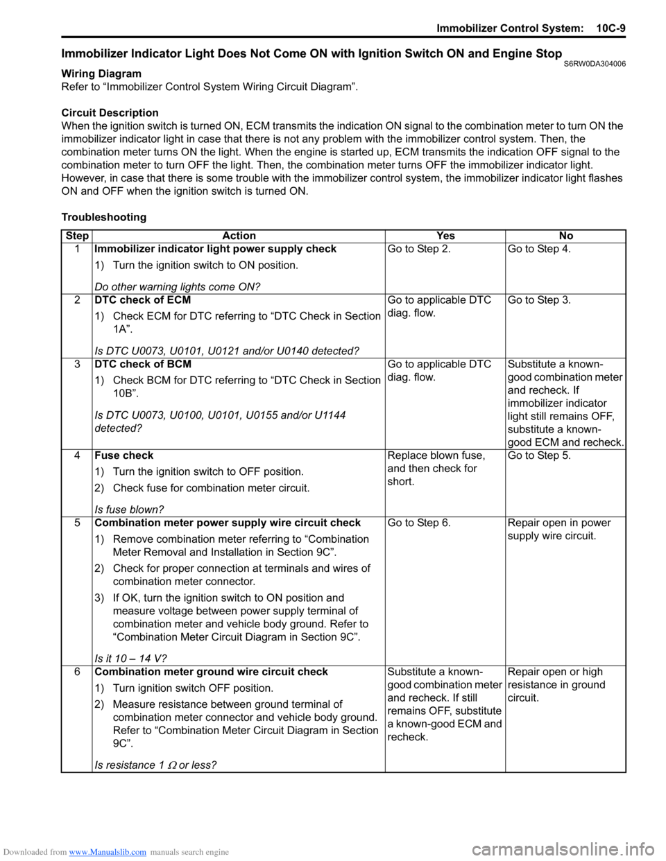
Immobilizer Indicator Light Does Not Come ON with Ignition Switch ON and Engine StopS6RW0DA304006
Wiring Diagram
Refer to “Immobilizer Control System Wiring Circuit Diagram”.
Circuit Description
When the ignition switch is turned ON, ECM transmits the indication ON signal to the combination meter to turn ON the
immobilizer indicator light in case that there is not any problem with the immobilizer control system. Then, the
combination meter turns ON the light. When the engine is started up, ECM transmits the indication OFF signal to the
combination meter to turn OFF the light. Then, the combination meter turns OFF the immobilizer indicator light.
However, in case that there is some trouble with the immobilizer control system, the immobilizer indicator light flashes
ON and OFF when the ignition switch is turned ON.
Troubleshooting
Step Action Yes No
1Immobilizer indicator light power supply check
1) Turn the ignition switch to ON position.
Do other warning lights come ON?Go to Step 2. Go to Step 4.
2DTC check of ECM
1) Check ECM for DTC referring to “DTC Check in Section
1A”.
Is DTC U0073, U0101, U0121 and/or U0140 detected?Go to applicable DTC
diag. flow.Go to Step 3.
3DTC check of BCM
1) Check BCM for DTC referring to “DTC Check in Section
10B”.
Is DTC U0073, U0100, U0101, U0155 and/or U1144
detected?Go to applicable DTC
diag. flow.Substitute a known-
good combination meter
and recheck. If
immobilizer indicator
light still remains OFF,
substitute a known-
good ECM and recheck.
4Fuse check
1) Turn the ignition switch to OFF position.
2) Check fuse for combination meter circuit.
Is fuse blown?Replace blown fuse,
and then check for
short.Go to Step 5.
5Combination meter power supply wire circuit check
1) Remove combination meter referring to “Combination
Meter Removal and Installation in Section 9C”.
2) Check for proper connection at terminals and wires of
combination meter connector.
3) If OK, turn the ignition switch to ON position and
measure voltage between power supply terminal of
combination meter and vehicle body ground. Refer to
“Combination Meter Circuit Diagram in Section 9C”.
Is it 10 – 14 V?Go to Step 6. Repair open in power
supply wire circuit.
6Combination meter ground wire circuit check
1) Turn ignition switch OFF position.
2) Measure resistance between ground terminal of
combination meter connector and vehicle body ground.
Refer to “Combination Meter Circuit Diagram in Section
9C”.
Is resistance 1
Ω or less?Substitute a known-
good combination meter
and recheck. If still
remains OFF, substitute
a known-good ECM and
recheck.Repair open or high
resistance in ground
circuit.
Page 1513 of 1556

Downloaded from www.Manualslib.com manuals search engine Immobilizer Control System: 10C-11
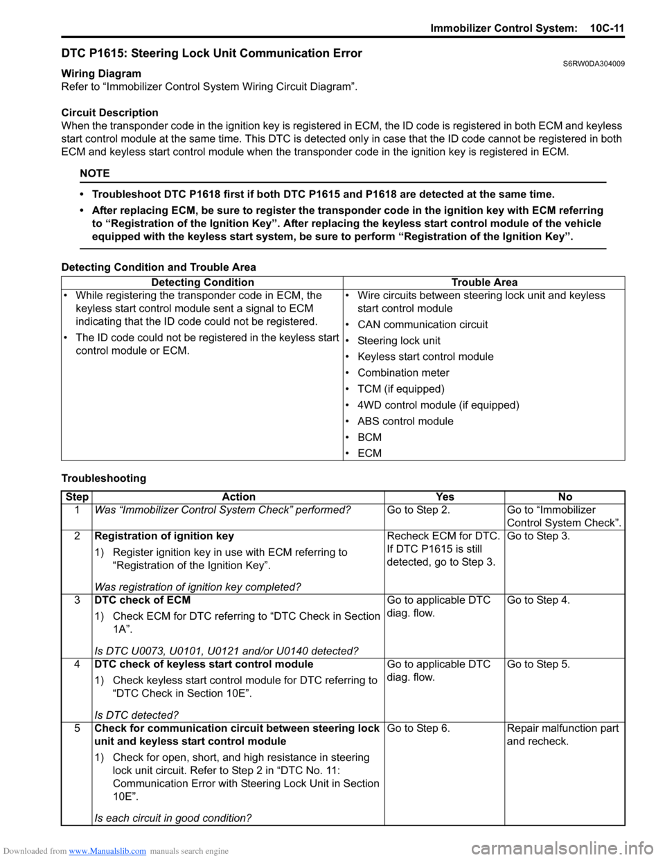
DTC P1615: Steering Lock Unit Communication ErrorS6RW0DA304009
Wiring Diagram
Refer to “Immobilizer Control System Wiring Circuit Diagram”.
Circuit Description
When the transponder code in the ignition key is registered in ECM, the ID code is registered in both ECM and keyless
start control module at the same time. This DTC is detected only in case that the ID code cannot be registered in both
ECM and keyless start control module when the transponder code in the ignition key is registered in ECM.
NOTE
• Troubleshoot DTC P1618 first if both DTC P1615 and P1618 are detected at the same time.
• After replacing ECM, be sure to register the transponder code in the ignition key with ECM referring
to “Registration of the Ignition Key”. After replacing the keyless start control module of the vehicle
equipped with the keyless start system, be sure to perform “Registration of the Ignition Key”.
Detecting Condition and Trouble Area
TroubleshootingDetecting Condition Trouble Area
• While registering the transponder code in ECM, the
keyless start control module sent a signal to ECM
indicating that the ID code could not be registered.
• The ID code could not be registered in the keyless start
control module or ECM.• Wire circuits between steering lock unit and keyless
start control module
• CAN communication circuit
• Steering lock unit
• Keyless start control module
• Combination meter
• TCM (if equipped)
• 4WD control module (if equipped)
• ABS control module
•BCM
•ECM
Step Action Yes No
1Was “Immobilizer Control System Check” performed?Go to Step 2. Go to “Immobilizer
Control System Check”.
2Registration of ignition key
1) Register ignition key in use with ECM referring to
“Registration of the Ignition Key”.
Was registration of ignition key completed?Recheck ECM for DTC.
If DTC P1615 is still
detected, go to Step 3.Go to Step 3.
3DTC check of ECM
1) Check ECM for DTC referring to “DTC Check in Section
1A”.
Is DTC U0073, U0101, U0121 and/or U0140 detected?Go to applicable DTC
diag. flow.Go to Step 4.
4DTC check of keyless start control module
1) Check keyless start control module for DTC referring to
“DTC Check in Section 10E”.
Is DTC detected?Go to applicable DTC
diag. flow.Go to Step 5.
5Check for communication circuit between steering lock
unit and keyless start control module
1) Check for open, short, and high resistance in steering
lock unit circuit. Refer to Step 2 in “DTC No. 11:
Communication Error with Steering Lock Unit in Section
10E”.
Is each circuit in good condition?Go to Step 6. Repair malfunction part
and recheck.
Page 1517 of 1556

Downloaded from www.Manualslib.com manuals search engine Immobilizer Control System: 10C-15
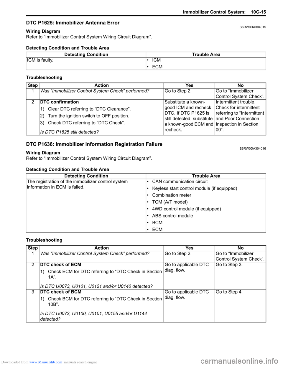
DTC P1625: Immobilizer Antenna ErrorS6RW0DA304015
Wiring Diagram
Refer to “Immobilizer Control System Wiring Circuit Diagram”.
Detecting Condition and Trouble Area
Troubleshooting
DTC P1636: Immobilizer Information Registration FailureS6RW0DA304016
Wiring Diagram
Refer to “Immobilizer Control System Wiring Circuit Diagram”.
Detecting Condition and Trouble Area
TroubleshootingDetecting Condition Trouble Area
ICM is faulty. • ICM
•ECM
Step Action Yes No
1Was “Immobilizer Control System Check” performed?Go to Step 2. Go to “Immobilizer
Control System Check”.
2DTC confirmation
1) Clear DTC referring to “DTC Clearance”.
2) Turn the ignition switch to OFF position.
3) Check DTC referring to “DTC Check”.
Is DTC P1625 still detected?Substitute a known-
good ICM and recheck
DTC. If DTC P1625 is
still detected, substitute
a known-good ECM and
recheck.Intermittent trouble.
Check for intermittent
referring to “Intermittent
and Poor Connection
Inspection in Section
00”.
Detecting Condition Trouble Area
The registration of the immobilizer control system
information in ECM is failed.• CAN communication circuit
• Keyless start control module (if equipped)
• Combination meter
• TCM (A/T model)
• 4WD control module (if equipped)
• ABS control module
•BCM
•ECM
Step Action Yes No
1Was “Immobilizer Control System Check” performed?Go to Step 2. Go to “Immobilizer
Control System Check”.
2DTC check of ECM
1) Check ECM for DTC referring to “DTC Check in Section
1A”.
Is DTC U0073, U0101, U0121 and/or U0140 detected?Go to applicable DTC
diag. flow.Go to Step 3.
3DTC check of BCM
1) Check BCM for DTC referring to “DTC Check in Section
10B”.
Is DTC U0073, U0100, U0101, U0155 and/or U1144
detected?Go to applicable DTC
diag. flow.Go to Step 4.
Page 1518 of 1556

Downloaded from www.Manualslib.com manuals search engine 10C-16 Immobilizer Control System:
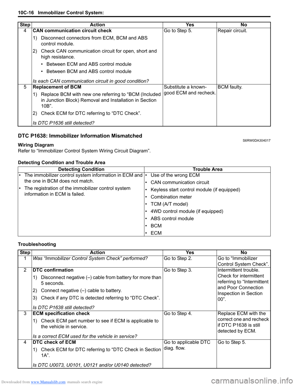
DTC P1638: Immobilizer Information MismatchedS6RW0DA304017
Wiring Diagram
Refer to “Immobilizer Control System Wiring Circuit Diagram”.
Detecting Condition and Trouble Area
Troubleshooting4CAN communication circuit check
1) Disconnect connectors from ECM, BCM and ABS
control module.
2) Check CAN communication circuit for open, short and
high resistance.
• Between ECM and ABS control module
• Between BCM and ABS control module
Is each CAN communication circuit in good condition?Go to Step 5. Repair circuit.
5Replacement of BCM
1) Replace BCM with new one referring to “BCM (Included
in Junction Block) Removal and Installation in Section
10B”.
2) Check ECM for DTC referring to “DTC Check”.
Is DTC P1636 still detected?Substitute a known-
good ECM and recheck.BCM faulty. Step Action Yes No
Detecting Condition Trouble Area
• The immobilizer control system information in ECM and
the one in BCM does not match.
• The registration of the immobilizer control system
information in ECM is failed.• Use of the wrong ECM
• CAN communication circuit
• Keyless start control module (if equipped)
• Combination meter
• TCM (A/T model)
• 4WD control module (if equipped)
• ABS control module
•BCM
•ECM
Step Action Yes No
1Was “Immobilizer Control System Check” performed?Go to Step 2. Go to “Immobilizer
Control System Check”.
2DTC confirmation
1) Disconnect negative (–) cable from battery for more than
5 seconds.
2) Connect negative (–) cable to battery.
3) Check if any DTC is detected referring to “DTC Check”.
Is DTC P1638 still detected?Go to Step 3. Intermittent trouble.
Check for intermittent
referring to “Intermittent
and Poor Connection
Inspection in Section
00”.
3ECM specification check
1) Check ECM part number to see if ECM is applicable to
the vehicle in service.
Is a correct ECM used for the vehicle in service?Go to Step 4. Replace ECM with the
correct one and recheck
if DTC P1638 is still
detected by ECM.
4DTC check of ECM
1) Check ECM for DTC referring to “DTC Check in Section
1A”.
Is DTC U0073, U0101, U0121 and/or U0140 detected?Go to applicable DTC
diag. flow.Go to Step 5.