2006 SUZUKI SX4 belt diagram
[x] Cancel search: belt diagramPage 1087 of 1556
Downloaded from www.Manualslib.com manuals search engine Air Bag System: 8B-48
DTC B1051 / B1055: Seat Belt Pretensioner Circuit High ResistanceS6RW0D8204026
DTC B1051: Driver Seat Belt Pretensioner Circuit High Resistance
DTC B1055: Passenger Seat Belt Pretensioner Circuit High Resistance
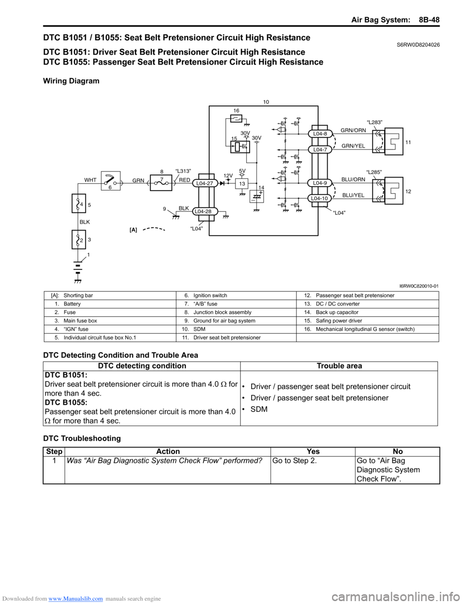
Wiring Diagram
DTC Detecting Condition and Trouble Area
DTC Troubleshooting
“L04”[A]
BLK
L04-28
6 8
7
RED
GRN“L313”L04-27
910
15
13
16
12V5V30V 30V
14
1
2 BLKWHT3
4
5
“L04”
GRN/ORN
GRN/YEL
BLU/ORN
BLU/YEL
L04-9
L04-7
L04-8
11
12 “L283”
L04-10
“L285”
I6RW0C820010-01
[A]: Shorting bar 6. Ignition switch 12. Passenger seat belt pretensioner
1. Battery 7. “A/B” fuse 13. DC / DC converter
2. Fuse 8. Junction block assembly 14. Back up capacitor
3. Main fuse box 9. Ground for air bag system 15. Safing power driver
4. “IGN” fuse 10. SDM 16. Mechanical longitudinal G sensor (switch)
5. Individual circuit fuse box No.1 11. Driver seat belt pretensioner
DTC detecting condition Trouble area
DTC B1051:
Driver seat belt pretensioner circuit is more than 4.0 Ω for
more than 4 sec.
DTC B1055:
Passenger seat belt pretensioner circuit is more than 4.0
Ω for more than 4 sec.• Driver / passenger seat belt pretensioner circuit
• Driver / passenger seat belt pretensioner
•SDM
Step Action Yes No
1Was “Air Bag Diagnostic System Check Flow” performed?Go to Step 2. Go to “Air Bag
Diagnostic System
Check Flow”.
Page 1090 of 1556
Downloaded from www.Manualslib.com manuals search engine 8B-51 Air Bag System:
DTC B1052 / B1056: Seat Belt Pretensioner Circuit Low ResistanceS6RW0D8204027
DTC B1052: Driver Seat Belt Pretensioner Circuit Low Resistance
DTC B1056: Passenger Seat Belt Pretensioner Circuit Low Resistance
Wiring Diagram
Refer to “DTC B1051 / B1055: Seat Belt Pretensioner Circuit High Resistance”.
DTC Detecting Condition and Trouble Area
DTC TroubleshootingDTC detecting condition Trouble area
DTC B1052:
Driver seat belt pretensioner circuit is less than 0.9 Ω for
more than 4 sec.
DTC B1056:
Passenger seat belt pretensioner circuit is less than 0.9 Ω
for more than 4 sec.• Driver / passenger seat belt pretensioner circuit
• Driver / passenger seat belt pretensioner
•SDM
Step Action Yes No
1Was “Air Bag Diagnostic System Check Flow” performed?Go to Step 2. Go to “Air Bag
Diagnostic System
Check Flow”.
2Seat belt pretensioner circuit check
1) With ignition switch turned OFF, remove center pillar
lower trim of applicable side and disconnect applicable
seat belt pretensioner connector “L283” or “L285”.
2) Check for proper connection to applicable seat belt
pretensioner at terminals in “L283” or “L285” connector.
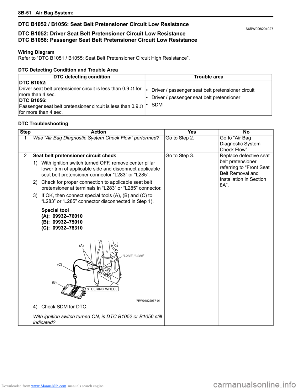
3) If OK, then connect special tools (A), (B) and (C) to
“L283” or “L285” connector disconnected in Step 1).
Special tool
(A): 09932–76010
(B): 09932–75010
(C): 09932–78310
4) Check SDM for DTC.
With ignition switch turned ON, is DTC B1052 or B1056 still
indicated?Go to Step 3. Replace defective seat
belt pretensioner
referring to “Front Seat
Belt Removal and
Installation in Section
8A”.
STEERING WHEEL
(B)(C)(A)
“L283”, “L285”
I7RW01822057-01
Page 1091 of 1556
Downloaded from www.Manualslib.com manuals search engine Air Bag System: 8B-52
NOTE
Upon completion of inspection and repair work, perform the following items.
• Reconnect all air bag system components and ensure all components are properly mounted.
• Clear DTCs referring to “DTC Clearance”, if any.
• Repeat “Air Bag Diagnostic System Check” to confirm that the trouble has been corrected.
DTC B1053 / B1057: Seat Belt Pretensioner Shorted to GroundS6RW0D8204028
DTC B1053: Driver Seat Belt Pretensioner Shorted to Ground
DTC B1057: Passenger Seat Belt Pretensioner Shorted to Ground
Wiring Diagram
Refer to “DTC B1051 / B1055: Seat Belt Pretensioner Circuit High Resistance”.
DTC Detecting Condition and Trouble Area3Seat belt pretensioner circuit resistance check
1) Disconnect special tools from applicable seat belt
pretensioner connector.
2) Disconnect SDM connector “L04”.
3) Check for proper connection to SDM at terminals “L04-7”
and “L04-8” (for DTC B1052) or terminals “L04-9” and
“L04-10” (for DTC B1056).
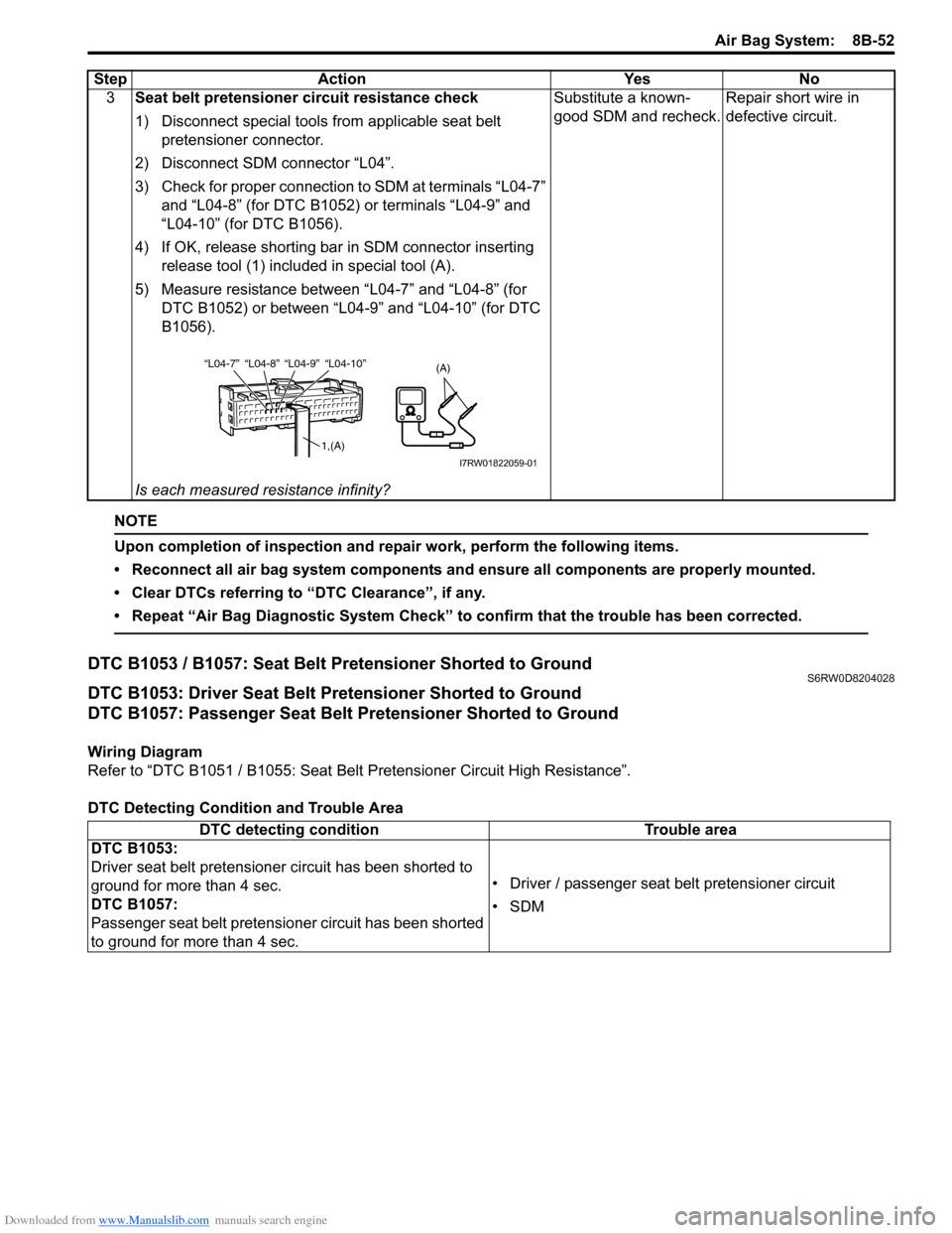
4) If OK, release shorting bar in SDM connector inserting
release tool (1) included in special tool (A).
5) Measure resistance between “L04-7” and “L04-8” (for
DTC B1052) or between “L04-9” and “L04-10” (for DTC
B1056).
Is each measured resistance infinity?Substitute a known-
good SDM and recheck.Repair short wire in
defective circuit. Step Action Yes No
“L04-8” “L04-9” “L04-10” “L04-7”(A)
1,(A)
I7RW01822059-01
DTC detecting condition Trouble area
DTC B1053:
Driver seat belt pretensioner circuit has been shorted to
ground for more than 4 sec.
DTC B1057:
Passenger seat belt pretensioner circuit has been shorted
to ground for more than 4 sec.• Driver / passenger seat belt pretensioner circuit
•SDM
Page 1093 of 1556
Downloaded from www.Manualslib.com manuals search engine Air Bag System: 8B-54
DTC B1054 / B1058: Seat Belt Pretensioner Circuit Shorted to Power SupplyS6RW0D8204029
DTC B1054: Driver Seat Belt Pretensioner Circuit Shorted to Power Supply
DTC B1058: Passenger Seat Belt Pretensioner Circuit Shorted to Power Supply
Wiring Diagram
Refer to “DTC B1051 / B1055: Seat Belt Pretensioner Circuit High Resistance”.
DTC Detecting Condition and Trouble Area
DTC Troubleshooting
NOTE
Upon completion of inspection and repair work, perform the following items.
• Reconnect all air bag system components and ensure all components are properly mounted.
• Clear DTCs referring to “DTC Clearance”, if any.
• Repeat “Air Bag Diagnostic System Check” to confirm that the trouble has been corrected.
DTC detecting condition Trouble area
DTC B1054:
Driver seat belt pretensioner circuit has been shorted to
power supply for more than 4 sec.
DTC B1058:
Passenger seat belt pretensioner circuit has been shorted
to power supply for more than 4 sec.• Driver / passenger seat belt pretensioner circuit
•SDM
Step Action Yes No
1Was “Air Bag Diagnostic System Check Flow” performed?Go to Step 2. Go to “Air Bag
Diagnostic System
Check Flow”.
2Seat belt pretensioner circuit check
1) With ignition switch turned OFF, remove center pillar
lower trim of applicable side and disconnect applicable
seat belt pretensioner connector “L283” or “L285”.
2) Disconnect SDM connector “L04”.
3) Check for proper connection to applicable seat belt
pretensioner at terminals in “L283” or “L285”.
4) Check for proper connection to SDM at terminals “L04-7”
and “L04-8” (for DTC B1054) or terminals “L04-9” and
“L04-10” (for DTC B1058).
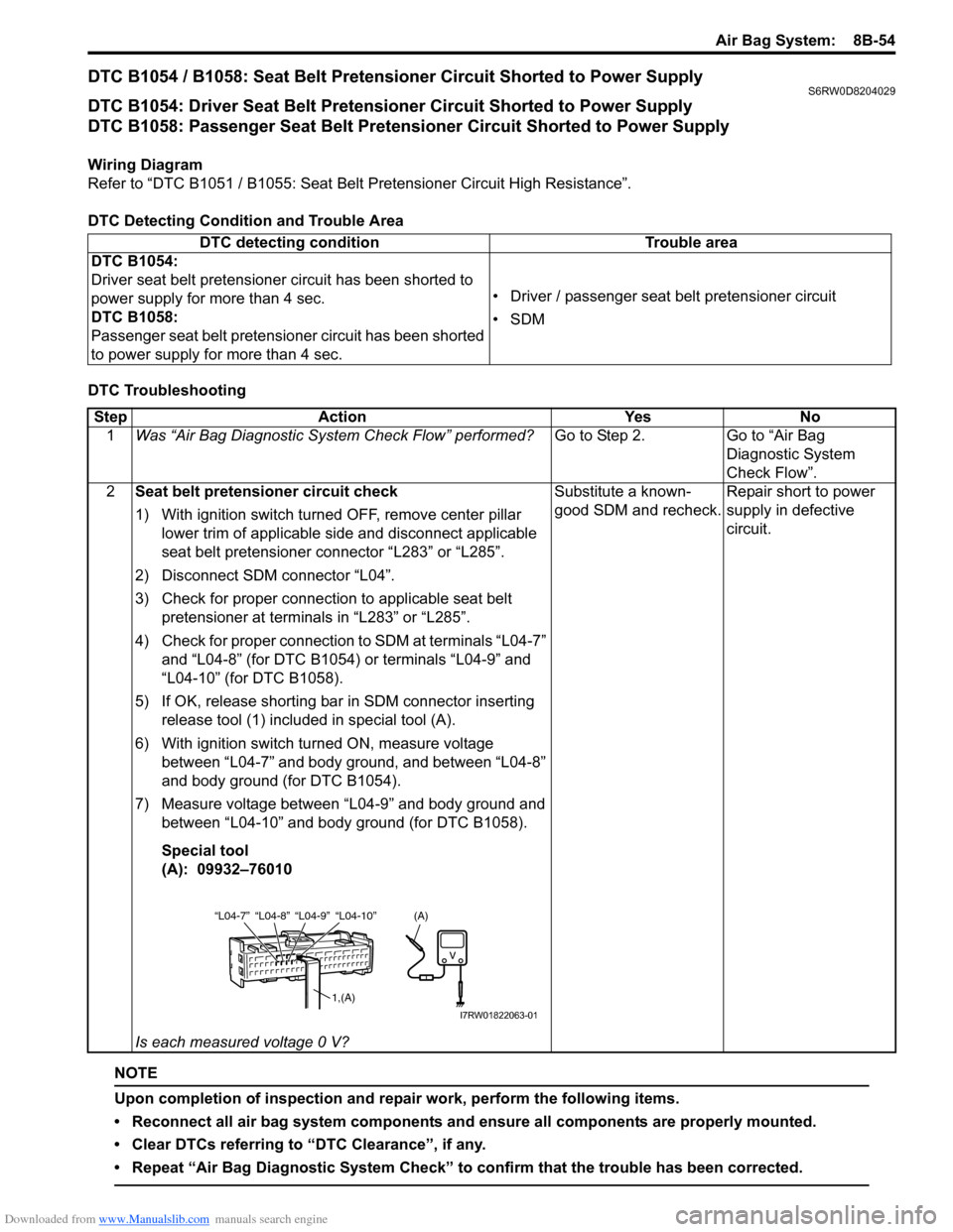
5) If OK, release shorting bar in SDM connector inserting
release tool (1) included in special tool (A).
6) With ignition switch turned ON, measure voltage
between “L04-7” and body ground, and between “L04-8”
and body ground (for DTC B1054).
7) Measure voltage between “L04-9” and body ground and
between “L04-10” and body ground (for DTC B1058).
Special tool
(A): 09932–76010
Is each measured voltage 0 V?Substitute a known-
good SDM and recheck.Repair short to power
supply in defective
circuit.
“L04-8” “L04-9” “L04-10” “L04-7”
1,(A)
(A)
I7RW01822063-01
Page 1163 of 1556
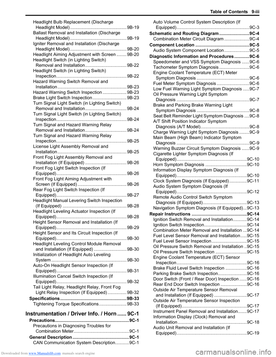
Downloaded from www.Manualslib.com manuals search engine Table of Contents 9-iii
Headlight Bulb Replacement (Discharge
Headlight Model) ............................................. 9B-19
Ballast Removal and Installation (Discharge
Headlight Model) ............................................. 9B-19
Igniter Removal and Installation (Discharge
Headlight Model) ............................................. 9B-20
Headlight Aiming Adjustment with Screen ........ 9B-20
Headlight Switch (in Lighting Switch)
Removal and Installation................................. 9B-22
Headlight Switch (in Lighting Switch)
Inspection........................................................ 9B-22
Hazard Warning Switch Removal and
Installation ....................................................... 9B-23
Hazard Warning Switch Inspection ................... 9B-23
Brake Light Switch Inspection ........................... 9B-23
Turn Signal Light Switch (in Lighting Switch)
Removal and Installation................................. 9B-24
Turn Signal Light Switch (in Lighting Switch)
Inspection........................................................ 9B-24
Turn Signal and Hazard Warning Relay
Removal and Installation................................. 9B-24
Turn Signal and Hazard Warning Relay
Inspection........................................................ 9B-25
License Light Assembly Removal and
Installation ....................................................... 9B-25
Front Fog Light Assembly Removal and
Installation (If Equipped) ................................. 9B-26
Front Fog Light Switch Inspection (If
Equipped)........................................................ 9B-26
Front Fog Light Aiming Adjustment with
Screen (If Equipped) ....................................... 9B-26
Rear Fog Light Switch Inspection (If
Equipped)........................................................ 9B-27
Headlight Manual Levering Switch Inspection
(If Equipped) ................................................... 9B-28
Headlight Leveling Actuator Inspection (If
Equipped)........................................................ 9B-28
Height Sensor Removal and Installation (If
Equipped)........................................................ 9B-29
Height Sensor and Its Circuit Inspection (If
Equipped)........................................................ 9B-30
Headlight Leveling Control Module Removal
and Installation (If Equipped) .......................... 9B-30
Initialization of Headlight Auto Leveling
System ............................................................ 9B-30
Auto-On Headlight Sensor Inspection (If
Equipped)........................................................ 9B-31
Illumination Cancel Switch Inspection (If
Equipped)........................................................ 9B-32
Tail Light Relay, Headlight Relay, Front Fog
Light Relay Inspection (If Equipped) ............... 9B-32
Specifications..................................................... 9B-33
Tightening Torque Specifications ...................... 9B-33
Instrumentation / Driver Info. / Horn ...... 9C-1
Precautions........................................................... 9C-1
Precautions in Diagnosing Troubles for
Combination Meter............................................ 9C-1
General Description ............................................. 9C-1
CAN Communication System Description........... 9C-1Auto Volume Control System Description (If
Equipped) ..........................................................9C-3
Schematic and Routing Diagram ........................9C-4
Combination Meter Circuit Diagram ....................9C-4
Component Location ...........................................9C-5
Audio System Component Location ....................9C-5
Diagnostic Information and Procedures ............9C-6
Speedometer and VSS Symptom Diagnosis ......9C-6
Tachometer Symptom Diagnosis ........................9C-6
Engine Coolant Temperature (ECT) Meter
Symptom Diagnosis ..........................................9C-6
Fuel Meter Symptom Diagnosis ..........................9C-6
Low Fuel Warning Light Symptom Diagnosis .....9C-7
Oil Pressure Warning Light Symptom
Diagnosis ..........................................................9C-7
Brake and Parking Brake Warning Light
Symptom Diagnosis ..........................................9C-8
Seat Belt Reminder Light Symptom Diagnosis ....9C-8
A/T Shift Position Indicator Symptom
Diagnosis (A/T Model).......................................9C-8
Charge Warning Light Symptom Diagnosis ........9C-9
Main Beam (High Beam) Indicator Symptom
Diagnosis ..........................................................9C-9
Warning Buzzer Circuit Symptom Diagnosis ......9C-9
Cigarette Lighter Symptom Diagnosis (If
Equipped) ........................................................9C-10
Horn Symptom Diagnosis .................................9C-10
Information Display Symptom Diagnosis (If
Equipped) ........................................................9C-10
Clock System Diagnosis (If Equipped) ..............9C-11
Audio System Symptom Diagnosis (If
Equipped) ........................................................9C-12
Remote Audio Control Switch Symptom
Diagnosis (If Equipped) ...................................9C-13
Navigation Symptom Diagnosis (If Equipped)...9C-13
Repair Instructions ............................................9C-14
Ignition Switch Removal and Installation...........9C-14
Ignition Switch Inspection..................................9C-14
Combination Meter Removal and Installation ...9C-14
Fuel Level Sensor Removal and Installation .....9C-15
Fuel Level Sensor Inspection ............................9C-15
Oil Pressure Switch Removal and Installation ..9C-15
Oil Pressure Switch Inspection .........................9C-15
Engine Coolant Temperature (ECT) Sensor
Inspection ........................................................9C-16
Brake Fluid Level Switch Inspection .................9C-16
Parking Brake Switch Inspection.......................9C-16
Door Switch (Front / Rear Door) Inspection ......9C-16
Rear End Door Switch Inspection .....................9C-16
Outside Air Temperature Sensor Removal
and Installation (If Equipped) ..........................9C-17
Outside Air Temperature Sensor Inspection
(If Equipped)....................................................9C-17
Instrument Panel Removal and Installation.......9C-17
Information Display (Clock) Removal and
Installation .......................................................9C-18
Audio Unit Removal and Installation (If
Equipped) ........................................................9C-19
Page 1273 of 1556
Downloaded from www.Manualslib.com manuals search engine Wiring Systems: 9A-106
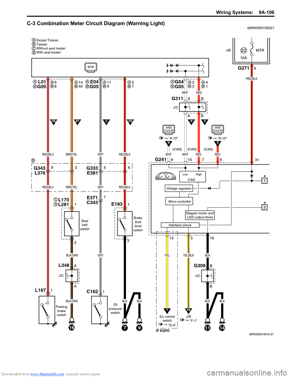
C-3 Combination Meter Circuit Diagram (Warning Light)S6RW0D910E021
J/BMTR
10A22
31
Stepper motor and
LED output driver
Voltage regulator
Micro controller
G2716
RED/BLK
516
YB
YEL/BLK
"F-1"
CAN
High Low
WHTWHTRED
RW
10G2419
7
L01
G05
RED/BLUBRN/YEL
L1671
Parking
brake
switch
1
2
A
A
16
BLK/ORN
BLK/ORN
J/C
L348B
B
J/C
G309
Seat
belt
switch
Oil
pressure
switch
J/B
13
Y
YEL
"D-4"
ILL cancel
switch
E371
C3437
G343
L37693G333
E38156
GRY
GRY
1C162
RED/BLK
RED/BLUBRN/YELGRYRED/BLK
E1831
Brake
fluid
level
switch
2
71114
BLK
BLK
BLK
9
BLKBLK
W
WHTRED
1
2
A
AB
B
J/C
G311
RBGBYRB
BCM
"A-10"
4WD
Cont.M
Interface circuit
RED
6
R"A-10"
4WD
Cont.M
(CAN) (CAN) (CAN)
IF EQPD
Except Taiwan
Taiwan
Without seat heater
With seat heater A
A
B
L170
L281C
D
G04
G05A
BE04
G05A
B
BCD
B
6
8AB14
40AB11
9AB5
7AB2
3AB4
1AB
I6RW0D910915-01