Page 458 of 1556

Downloaded from www.Manualslib.com manuals search engine 2B-21 Front Suspension:
Specifications
Tightening Torque SpecificationsS6RW0D2207001
NOTE
The specified tightening torque is also described in the following.
“Front Suspension Construction”
“Front Strut Assembly Components”
“Front Wheel Hub and Steering Knuckle Components”
“Front Suspension Frame, Stabilizer Bar and/or Bushing Components”
Reference:
For the tightening torque of fastener not specified in this section, refer to “Fasteners Information in Section 0A”. Fastening partTightening torque
Note
N⋅mkgf-mlb-ft
Tie-rod end lock nut 45 4.5 32.5�)
Strut bracket nut 140 14.0 101.5�) / �)
Brake hose mounting bolt 26 2.6 19.0�)
Stabilizer joint nut 50 5.0 36.5�) / �)
Strut nut 50 5.0 36.5�)
Wheel nut 85 8.5 61.5�) / �) / �) / �) / �)
Strut support lower nut 55 5.5 40.0�)
Suspension arm ball joint bolt 60 6.0 43.5�)
Wheel speed sensor mounting bolt 11 1.1 8.0�)
Tie-rod end nut 45 4.5 32.5�)
Caliper carrier bolt 85 8.5 61.5�)
Drive shaft nut 200 20.0 145.0�)
Suspension control arm bolt 95 9.5 69.0�) / �)
Stabilizer bar mounting bracket bolt Tighten 23 N⋅m (2.3 kgf-m, 17.0 lb-ft) to
specified procedure�)
Front suspension frame mounting bolt 150 15.0 108.5�)
Page 480 of 1556

Downloaded from www.Manualslib.com manuals search engine 3A-1 Drive Shaft / Axle: Front
Driveline / Axle
Drive Shaft / Axle
Front
General Description
Front Drive Shaft ConstructionS6RW0D3111001
A constant velocity ball joint is used on the wheel side of both right and left side drive shaft assemblies. For A/T
vehicle, a tripod type constant velocity joint is used on the differential side and center shaft side. For M/T vehicle, a
double offset type constant velocity joint (DOJ) is used on the differential side and center shaft side. The drive shaft
can slide through the tripod joint or the double offset joint (DOJ) in the extension/contraction direction.
Component Location
Front Drive Shaft Assembly Components LocationS6RW0D3113001
I6RW0D311001-01
1. To transaxle 7. Wheel nut : 200 N⋅m (20.0 kgf-m, 145.0 lb-ft)
2. Drive shaft assembly 8. Center shaft assembly (if equipped) : 85 N⋅m (8.5 kgf-m, 61.5 lb-ft)
3. Tie-rod end 9. Center bearing support bolts (if equipped) : 55 N⋅m (5.5 kgf-m, 40.0 lb-ft)
4. Tie-rod end nut 10. Washer : Do not reuse.
5. Ball stud bolt : 45 N⋅m (4.5 kgf-m, 32.5 lb-ft)
6. Drive shaft nut
: After tightening nut to specified torque,
caulk nut securely.:60 N⋅m (6.0 kgf-m, 43.5 lb-ft)
Page 481 of 1556

Downloaded from www.Manualslib.com manuals search engine Drive Shaft / Axle: Front 3A-2
Diagnostic Information and Procedures
Front Drive Shaft Symptom DiagnosisS6RW0D3114001
Repair Instructions
Front Drive Shaft ComponentsS6RW0D3116001
Condition Possible cause Correction / Reference Item
Abnormal noiseWorn or breakage of the drive shaft jointReplace.
Worn or breakage of the center bearingReplace.
1
9A
1112
10
9A
13
3
2
1
1
14
4
5
6
5
4
7
8
15
[A]
3
4
5
6
5
4
7
16
1
17
18
15
[B]
I6RW0D311002-01
[A]: M/T model 10. Center bearing support circlip
[B]: A/T model 11. Center bearing support
1. Circlip12. Center bearing
2. Differential side joint (Constant velocity DOJ)
: Apply dark gray grease included in spare part to joint.13. Center shaft
3. Snap ring 14. Cage
4. Boot band (Large) 15. Damper (if equipped)
5. Boot 16. Differential side joint (Constant velocity tripod joint)
: Apply dark gray grease included in spare part to joint.
6. Boot band (Small) 17. Center shaft side joint (Constant velocity tripod joint)
: Apply dark gray grease included in spare part to joint.
7. Wheel side joint (Constant velocity ball joint)
: Apply black grease included in spare part to joint.18. Tripod joint spider
: Never disassemble.
8. Center shaft side joint (Constant velocity DOJ)
: Apply dark gray grease included in spare part to joint.: Do not reuse.
9. Oil seal
: Apply grease to oil seal lip.
Page 482 of 1556

Downloaded from www.Manualslib.com manuals search engine 3A-3 Drive Shaft / Axle: Front
Front Drive Shaft Assembly On-Vehicle
Inspection
S6RW0D3116002
• Check boots for breakage or deterioration.
• Check wheel side joint for rattle or smooth rotation.
• Check differential side (or center shaft side) joint for
smooth rotation.
If any abnormality is found, replace.
Front Drive Shaft Assembly Removal and
Installation
S6RW0D3116003
Removal
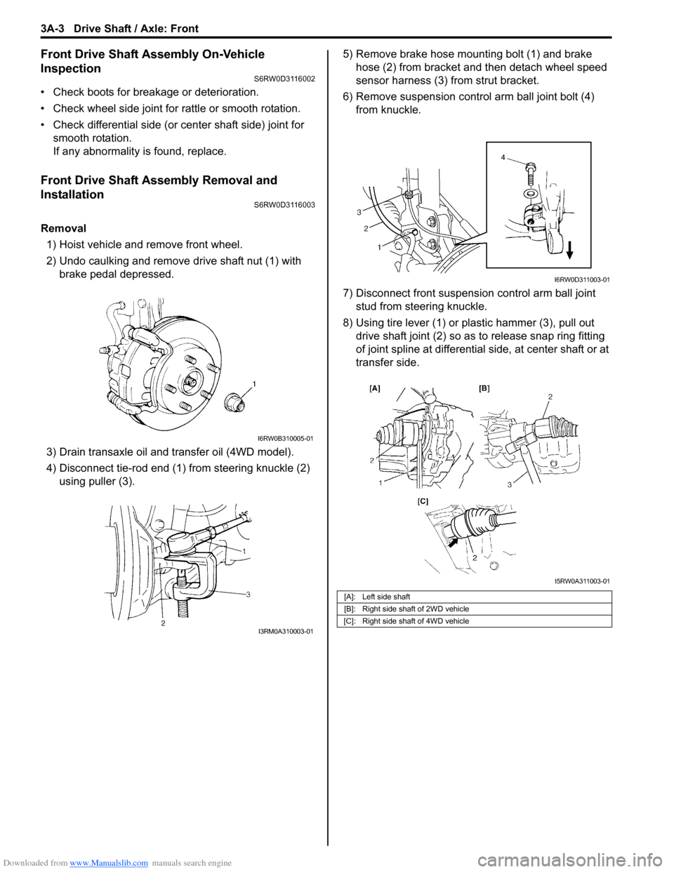
1) Hoist vehicle and remove front wheel.
2) Undo caulking and remove drive shaft nut (1) with
brake pedal depressed.
3) Drain transaxle oil and transfer oil (4WD model).
4) Disconnect tie-rod end (1) from steering knuckle (2)
using puller (3).5) Remove brake hose mounting bolt (1) and brake
hose (2) from bracket and then detach wheel speed
sensor harness (3) from strut bracket.
6) Remove suspension control arm ball joint bolt (4)
from knuckle.
7) Disconnect front suspension control arm ball joint
stud from steering knuckle.
8) Using tire lever (1) or plastic hammer (3), pull out
drive shaft joint (2) so as to release snap ring fitting
of joint spline at differential side, at center shaft or at
transfer side.
I6RW0B310005-01
I3RM0A310003-01
[A]: Left side shaft
[B]: Right side shaft of 2WD vehicle
[C]: Right side shaft of 4WD vehicle
I6RW0D311003-01
I5RW0A311003-01
Page 487 of 1556

Downloaded from www.Manualslib.com manuals search engine Drive Shaft / Axle: Front 3A-8
10) Install damper (1) to specified position on drive shaft.
Drive shaft damper installing position
“a”: 354 mm (13.9 in.) (right side)
“a”: 252 mm (9.9 in.) (left side)
11) Set new differential side (or center shaft side) small
band and new differential side (or center shaft side)
boot on shaft temporarily.
12) Drive in the cage (1) by using special tool.
Special tool
(A): 09913–84510
13) Install circlip (1) by using snap ring pliers (2).14) Apply grease to entire surface of cage. Use specified
grease in tube included in spare parts.
15) Insert cage into joint housing (2) and fit snap ring (1)
into groove of joint housing (2).
CAUTION!
Position opening of snap ring “c” so that it
will not be lined up with a ball.
16) Apply grease (including in spare parts) to inside of
joint housing (1).
Grease color
“A”: Dark gray
Amount
“A”: 75 – 95 g (2.6 – 3.4 oz) (right side)
“A”: 70 – 90 g (2.5 – 3.2 oz) (left side)
I5RW0A311004-01
(A)
1
I5RS0B310009-01
I5RS0B310010-01
I2RH01310036-01
I5RS0B310011-02
Page 494 of 1556
Downloaded from www.Manualslib.com manuals search engine 3A-15 Drive Shaft / Axle: Rear
Rear
General Description
Rear Drive Shaft ConstructionS6RW0D3121001
Refer to “Front Drive Shaft Construction”.
Repair Instructions
Rear Drive Shaft ComponentsS6RW0D3126001
I5RW0A312001-01
1. Differential side joint (Constant velocity DOJ joint)
: Apply dark gray grease included in spare part to
joint.6. Wheel side joint (Constant velocity ball joint)
: Apply black grease included in spare part to
joint.11. Boot (wheel side)
2. Snap ring 7. Cage : 175 N⋅m (17.5 kgf-m, 126.5 lb-ft)
3. Boot band (Large) 8. Drive shaft nut
: After tightening nut, caulk nut securely.: 80 N⋅m (8.0 kgf-m, 58.0 lb-ft)
4. Boot (Differential side) 9. Rear drive shaft flange nut : Do not reuse.
5. Boot band (Small) 10. Circrip
Page 566 of 1556

Downloaded from www.Manualslib.com manuals search engine 3D-1 Propeller Shafts:
Driveline / Axle
Propeller Shafts
Precautions
Propeller Shaft CautionS6RW0D3400001
CAUTION!
• All propeller shaft fasteners are an important attaching part in that it could affect the performance of
vital parts and systems, and/or could result in major repair expense. They must be replaced with one
of the same part number or with an equivalent part if replacement becomes necessary. Do not use a
replacement part of lesser quality or substitute design. Torque values must be used as specified
during reassembly to assure proper retention of this part.
• Never attempt to heat, quench or straighten any propeller shaft part. Replace it with a new part, or
damage to the part may result.
General Description
Propeller Shaft ConstructionS6RW0D3401001
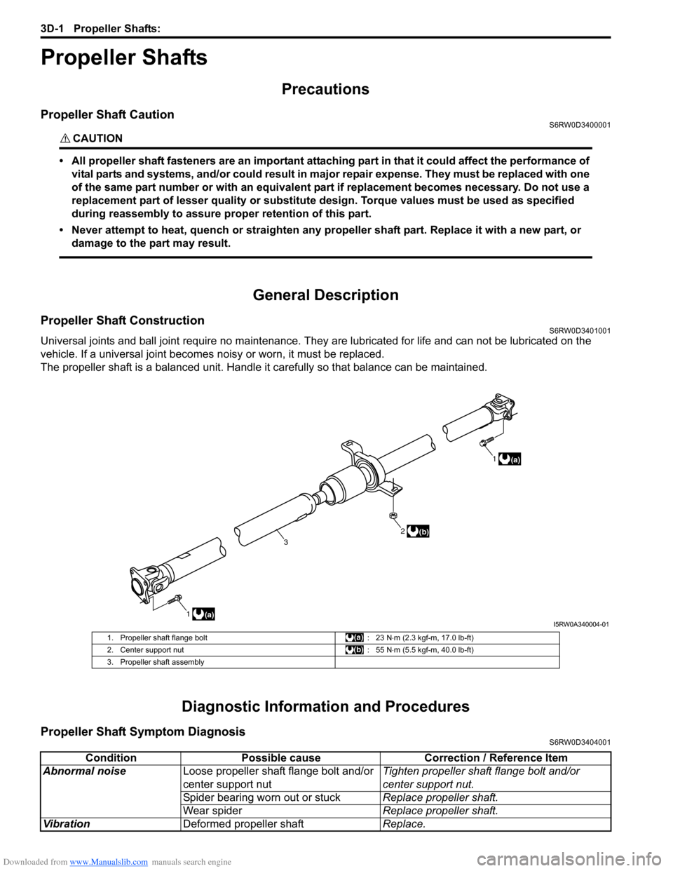
Universal joints and ball joint require no maintenance. They are lubricated for life and can not be lubricated on the
vehicle. If a universal joint becomes noisy or worn, it must be replaced.
The propeller shaft is a balanced unit. Handle it carefully so that balance can be maintained.
Diagnostic Information and Procedures
Propeller Shaft Symptom DiagnosisS6RW0D3404001
1(a)1
(a)
2
3(b)
I5RW0A340004-01
1. Propeller shaft flange bolt : 23 N⋅m (2.3 kgf-m, 17.0 lb-ft)
2. Center support nut : 55 N⋅m (5.5 kgf-m, 40.0 lb-ft)
3. Propeller shaft assembly
Condition Possible cause Correction / Reference Item
Abnormal noiseLoose propeller shaft flange bolt and/or
center support nutTighten propeller shaft flange bolt and/or
center support nut.
Spider bearing worn out or stuckReplace propeller shaft.
Wear spiderReplace propeller shaft.
VibrationDeformed propeller shaftReplace.
Page 567 of 1556

Downloaded from www.Manualslib.com manuals search engine Propeller Shafts: 3D-2
Repair Instructions
Propeller Shaft Joint CheckS6RW0D3406001
If universal joints and ball joint are suspected of
producing chattering or rattling noise, inspect them for
wear. For universal joint, check to see if cross spider
rattles in yokes are worn down and replace defective
propeller shaft assembly with new one.
Noise coming from universal joint and ball joint can be
easily distinguished from other noises because rhythm
of chattering or rattling is in step with cruising speed.
Noise is pronounced particularly on standing start or in
coasting condition (when braking effect of engine is
showing in the drive line).
Propeller Shaft Assembly Removal and
Installation
S6RW0D3406002
Removal
1) Hoist vehicle.
2) Before removing propeller shaft assembly, give
match marks (2) on joint flange and propeller shaft
as shown.
3) Separate propeller shaft assembly (1) from transfer
output flange and rear differential flange.4) Remove propeller shaft by removing center support
nuts (1).
CAUTION!
Use care not to drop it. Otherwise, vibration
may occur during driving.
Installation
Reverse removal procedure to install propeller shaft,
noting the following point.
• When installing propeller shaft, align the match marks
(2). Otherwise, vibration may occur during driving.
• Use the following specification to torque each bolt and
nut.
Tightening torque
Propeller shaft bolt: 23 N·m (2.3 kgf-m, 17.0 lb-ft)
Center support nut: 55 N·m (5.5 kgf-m, 40.0 lb-ft)
Propeller Shaft InspectionS6RW0D3406003
1) Check propeller shaft joints for wear, play and
damage. If any defect is found, replace.
2) Check propeller shaft center support for biting of
foreign matter, crack, abnormal noise and damage. If
any defect is found, replace.
I5JB0A340003-01
2
2
1
1
I5RW0A340002-01
1I5RW0A340003-01