Page 1133 of 1556

Downloaded from www.Manualslib.com manuals search engine Air Bag System: 8B-94
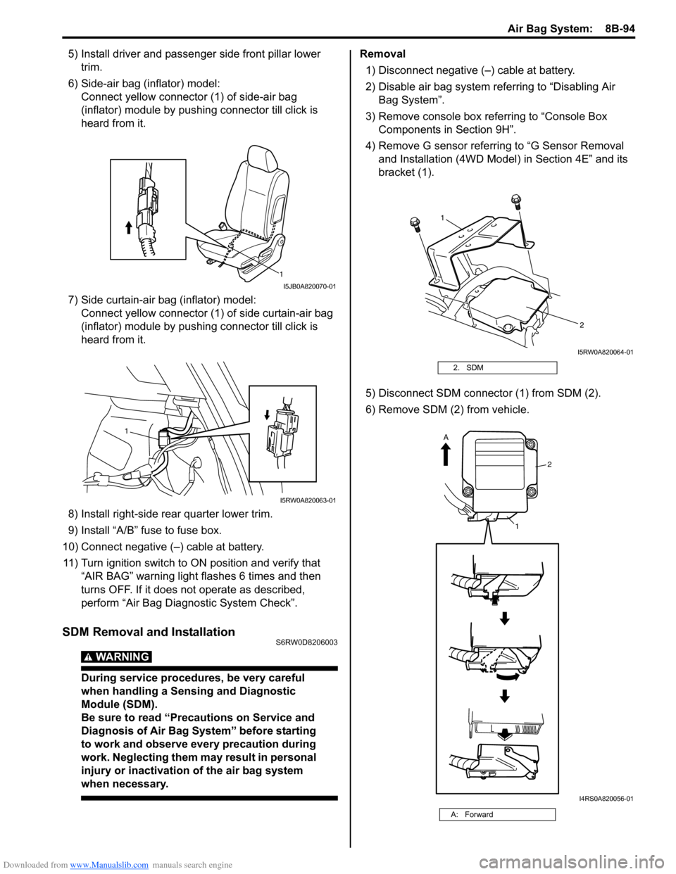
5) Install driver and passenger side front pillar lower
trim.
6) Side-air bag (inflator) model:
Connect yellow connector (1) of side-air bag
(inflator) module by pushing connector till click is
heard from it.
7) Side curtain-air bag (inflator) model:
Connect yellow connector (1) of side curtain-air bag
(inflator) module by pushing connector till click is
heard from it.
8) Install right-side rear quarter lower trim.
9) Install “A/B” fuse to fuse box.
10) Connect negative (–) cable at battery.
11) Turn ignition switch to ON position and verify that
“AIR BAG” warning light flashes 6 times and then
turns OFF. If it does not operate as described,
perform “Air Bag Diagnostic System Check”.
SDM Removal and InstallationS6RW0D8206003
WARNING!
During service procedures, be very careful
when handling a Sensing and Diagnostic
Module (SDM).
Be sure to read “Precautions on Service and
Diagnosis of Air Bag System” before starting
to work and observe every precaution during
work. Neglecting them may result in personal
injury or inactivation of the air bag system
when necessary.
Removal
1) Disconnect negative (–) cable at battery.
2) Disable air bag system referring to “Disabling Air
Bag System”.
3) Remove console box referring to “Console Box
Components in Section 9H”.
4) Remove G sensor referring to “G Sensor Removal
and Installation (4WD Model) in Section 4E” and its
bracket (1).
5) Disconnect SDM connector (1) from SDM (2).
6) Remove SDM (2) from vehicle.
1
I5JB0A820070-01
1
I5RW0A820063-01
2. SDM
A: Forward
1
2
I5RW0A820064-01
2
1
A
I4RS0A820056-01
Page 1394 of 1556

Downloaded from www.Manualslib.com manuals search engine 9E-9 Glass / Windows / Mirrors:
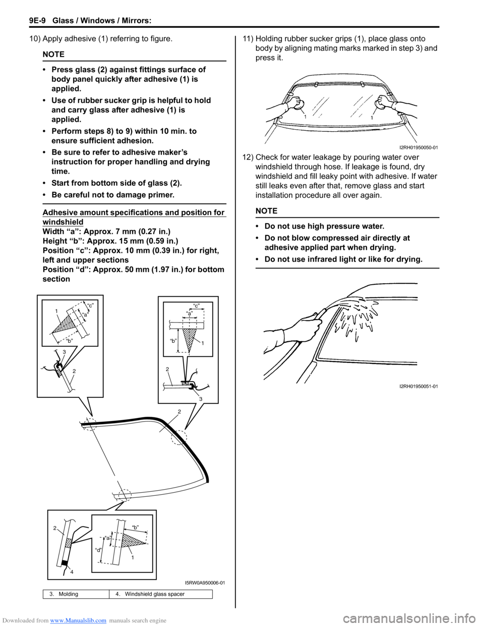
10) Apply adhesive (1) referring to figure.
NOTE
• Press glass (2) against fittings surface of
body panel quickly after adhesive (1) is
applied.
• Use of rubber sucker grip is helpful to hold
and carry glass after adhesive (1) is
applied.
• Perform steps 8) to 9) within 10 min. to
ensure sufficient adhesion.
• Be sure to refer to adhesive maker’s
instruction for proper handling and drying
time.
• Start from bottom side of glass (2).
• Be careful not to damage primer.
Adhesive amount specifications and position for
windshield
Width “a”: Approx. 7 mm (0.27 in.)
Height “b”: Approx. 15 mm (0.59 in.)
Position “c”: Approx. 10 mm (0.39 in.) for right,
left and upper sections
Position “d”: Approx. 50 mm (1.97 in.) for bottom
section11) Holding rubber sucker grips (1), place glass onto
body by aligning mating marks marked in step 3) and
press it.
12) Check for water leakage by pouring water over
windshield through hose. If leakage is found, dry
windshield and fill leaky point with adhesive. If water
still leaks even after that, remove glass and start
installation procedure all over again.
NOTE
• Do not use high pressure water.
• Do not blow compressed air directly at
adhesive applied part when drying.
• Do not use infrared light or like for drying.
3. Molding 4. Windshield glass spacer
2
“b”
“c”
2
3
1
“a”
3
2
1
“b”
“c”
“a”
2
4
1“b”
“d”
“a”
I5RW0A950006-01
I2RH01950050-01
I2RH01950051-01
Page 1511 of 1556

Downloaded from www.Manualslib.com manuals search engine Immobilizer Control System: 10C-9
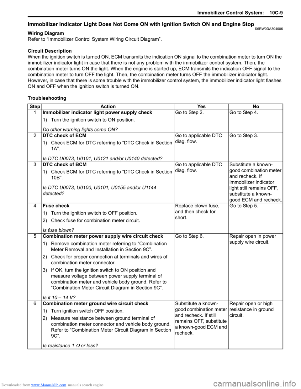
Immobilizer Indicator Light Does Not Come ON with Ignition Switch ON and Engine StopS6RW0DA304006
Wiring Diagram
Refer to “Immobilizer Control System Wiring Circuit Diagram”.
Circuit Description
When the ignition switch is turned ON, ECM transmits the indication ON signal to the combination meter to turn ON the
immobilizer indicator light in case that there is not any problem with the immobilizer control system. Then, the
combination meter turns ON the light. When the engine is started up, ECM transmits the indication OFF signal to the
combination meter to turn OFF the light. Then, the combination meter turns OFF the immobilizer indicator light.
However, in case that there is some trouble with the immobilizer control system, the immobilizer indicator light flashes
ON and OFF when the ignition switch is turned ON.
Troubleshooting
Step Action Yes No
1Immobilizer indicator light power supply check
1) Turn the ignition switch to ON position.
Do other warning lights come ON?Go to Step 2. Go to Step 4.
2DTC check of ECM
1) Check ECM for DTC referring to “DTC Check in Section
1A”.
Is DTC U0073, U0101, U0121 and/or U0140 detected?Go to applicable DTC
diag. flow.Go to Step 3.
3DTC check of BCM
1) Check BCM for DTC referring to “DTC Check in Section
10B”.
Is DTC U0073, U0100, U0101, U0155 and/or U1144
detected?Go to applicable DTC
diag. flow.Substitute a known-
good combination meter
and recheck. If
immobilizer indicator
light still remains OFF,
substitute a known-
good ECM and recheck.
4Fuse check
1) Turn the ignition switch to OFF position.
2) Check fuse for combination meter circuit.
Is fuse blown?Replace blown fuse,
and then check for
short.Go to Step 5.
5Combination meter power supply wire circuit check
1) Remove combination meter referring to “Combination
Meter Removal and Installation in Section 9C”.
2) Check for proper connection at terminals and wires of
combination meter connector.
3) If OK, turn the ignition switch to ON position and
measure voltage between power supply terminal of
combination meter and vehicle body ground. Refer to
“Combination Meter Circuit Diagram in Section 9C”.
Is it 10 – 14 V?Go to Step 6. Repair open in power
supply wire circuit.
6Combination meter ground wire circuit check
1) Turn ignition switch OFF position.
2) Measure resistance between ground terminal of
combination meter connector and vehicle body ground.
Refer to “Combination Meter Circuit Diagram in Section
9C”.
Is resistance 1
Ω or less?Substitute a known-
good combination meter
and recheck. If still
remains OFF, substitute
a known-good ECM and
recheck.Repair open or high
resistance in ground
circuit.
Page 1512 of 1556

Downloaded from www.Manualslib.com manuals search engine 10C-10 Immobilizer Control System:
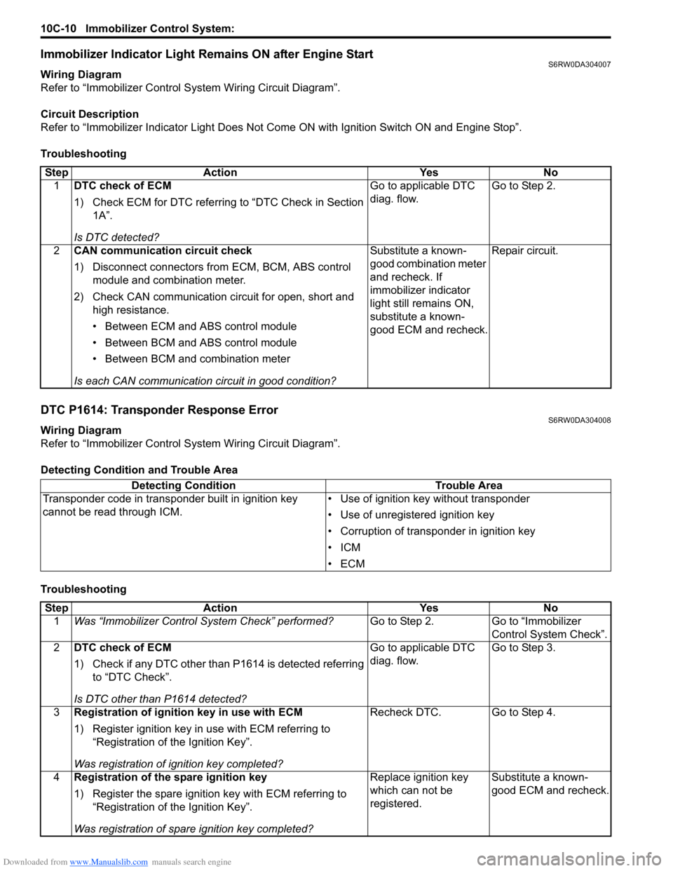
Immobilizer Indicator Light Remains ON after Engine StartS6RW0DA304007
Wiring Diagram
Refer to “Immobilizer Control System Wiring Circuit Diagram”.
Circuit Description
Refer to “Immobilizer Indicator Light Does Not Come ON with Ignition Switch ON and Engine Stop”.
Troubleshooting
DTC P1614: Transponder Response ErrorS6RW0DA304008
Wiring Diagram
Refer to “Immobilizer Control System Wiring Circuit Diagram”.
Detecting Condition and Trouble Area
TroubleshootingStep Action Yes No
1DTC check of ECM
1) Check ECM for DTC referring to “DTC Check in Section
1A”.
Is DTC detected?Go to applicable DTC
diag. flow.Go to Step 2.
2CAN communication circuit check
1) Disconnect connectors from ECM, BCM, ABS control
module and combination meter.
2) Check CAN communication circuit for open, short and
high resistance.
• Between ECM and ABS control module
• Between BCM and ABS control module
• Between BCM and combination meter
Is each CAN communication circuit in good condition?Substitute a known-
good combination meter
and recheck. If
immobilizer indicator
light still remains ON,
substitute a known-
good ECM and recheck.Repair circuit.
Detecting Condition Trouble Area
Transponder code in transponder built in ignition key
cannot be read through ICM.• Use of ignition key without transponder
• Use of unregistered ignition key
• Corruption of transponder in ignition key
•ICM
•ECM
Step Action Yes No
1Was “Immobilizer Control System Check” performed?Go to Step 2. Go to “Immobilizer
Control System Check”.
2DTC check of ECM
1) Check if any DTC other than P1614 is detected referring
to “DTC Check”.
Is DTC other than P1614 detected?Go to applicable DTC
diag. flow.Go to Step 3.
3Registration of ignition key in use with ECM
1) Register ignition key in use with ECM referring to
“Registration of the Ignition Key”.
Was registration of ignition key completed?Recheck DTC. Go to Step 4.
4Registration of the spare ignition key
1) Register the spare ignition key with ECM referring to
“Registration of the Ignition Key”.
Was registration of spare ignition key completed?Replace ignition key
which can not be
registered.Substitute a known-
good ECM and recheck.