2006 SUZUKI SX4 Sunload sensor
[x] Cancel search: Sunload sensorPage 994 of 1556
![SUZUKI SX4 2006 1.G Service Workshop Manual Downloaded from www.Manualslib.com manuals search engine 7B-54 Air Conditioning System: Automatic Type
DTC of A/C System detected by ECM
NOTE
When no DTC is detected, “FRE” [A] and “REC” [B] i SUZUKI SX4 2006 1.G Service Workshop Manual Downloaded from www.Manualslib.com manuals search engine 7B-54 Air Conditioning System: Automatic Type
DTC of A/C System detected by ECM
NOTE
When no DTC is detected, “FRE” [A] and “REC” [B] i](/manual-img/20/7612/w960_7612-993.png)
Downloaded from www.Manualslib.com manuals search engine 7B-54 Air Conditioning System: Automatic Type
DTC of A/C System detected by ECM
NOTE
When no DTC is detected, “FRE” [A] and “REC” [B] indicator lights on HVAC control module flash at
the same time in specific pattern.
Fail-Safe TableS6RW0D7224007
When any of the following malfunctions (DTCs) is detected, fail-safe mode is activated.
However, when HVAC control module detects normal operation of A/C system, fail-safe mode is canceled. DTC No. Detection itemDetecting condition
(DTC will set when detecting)MIL
P0481 Fan 2 Control Circuit
Refer to “Fail-Safe Table in Section 1A”. P0532A/C Refrigerant Pressure
Sensor Circuit Low
P0533A/C Refrigerant Pressure
Sensor Circuit High
H: ON a. About 3 seconds
L: OFF b. About 1 seconds
DTC No. Trouble AreaFail-Safe Operation
When ignition switch is turned ON
after malfunction is already detectedWhen malfunction is detected during
ignition switch is ON
�) B1502Inside air temperature
sensor circuitHVAC control module maintains last
normal value.HVAC control module controls actuators
assuming that inside air temperature is
25 °C (77 °F).
�) B1503A/C evaporator
temperature sensor
circuitHVAC control module assuming that
evaporator temperature is 0 °C (32 °F).• HVAC control module turns off A/C
switch signal.
• HVAC control module controls
actuators assuming that evaporator
temperature is 0 °C (32 °F).
�) B1504 Sunload sensor circuitHVAC control module maintains last
normal value.HVAC control module controls actuators
assuming that amount of sunlight is 0 W/
m
2.
�) B1520Temperature selector
malfunctionHVAC control module maintains last
normal value.HVAC control module controls actuators
assuming that setting of temperature
selector is 25 °C (77 °F) position.
�) B1521Blower speed selector
malfunctionHVAC control module maintains last
normal value.HVAC control module controls actuators
assuming that setting of blower speed
selector is low (1st) position.
�) B1522Air flow selector
malfunctionHVAC control module maintains last
normal value.HVAC control module controls actuators
assuming that setting of air flow selector
is DEF position.
[A]
[A]H
L
H
L [B]
[B]
baaba
baaba
I5RW0A722008-01
Page 997 of 1556

Downloaded from www.Manualslib.com manuals search engine Air Conditioning System: Automatic Type 7B-57
SUN LOAD (W/m2): This parameter indicates the
amount of sunlight detected by sunload sensor.
MODE CONT SWITCH (Air flow selector position,
AUTO, FACE, B/L, FOOT, D/F, DEF): This
parameter indicates the selected position of air flow
selector.
FAN CONT SWITCH (Blower speed selector, AUTO,
OFF, 1st – 8th): This parameter indicates the
selected position of blower speed selector.
FAN DESIRE VOLT (Fan desired voltage, V): This
parameter indicates the consumption voltage of
blower motor.
AIR MIX POS SENSOR (Temperature control
actuator position sensor, V): This parameter
indicates the input signal from position sensor in
temperature control actuator.
MODE POS SENSOR (Air flow control actuator
position sensor, V): This parameter indicates the
input signal from position sensor in air flow control
actuator.
A/C CONT SIG (A/C control signal, ON, OFF): This
parameter indicates the state of A/C switch.BLOWER LOAD SIG (Blower fan load signal, ON,
OFF): ON: Position of blower speed selector is 1st
position or more.
OFF: Position of blower speed selector is OFF
position.
AIR INTAKE MODE (Air intake selector position,
AUTO, FRE, REC): This parameter indicates the
selected position of air intake selector.
REFRIGERANT PRESSURE (A/C refrigerant absolute
pressure, kPa): This parameter indicates the A/C
refrigerant absolute pressure calculated by ECM
A/C COMP CLUCH (A/C compressor magnet clutch,
ON, OFF): This parameter indicates the state of the
A/C compressor magnet clutch.
VEHICLE SPEED (km/h, mph): This parameter
indicates the vehicle speed calculated by ECM.
ENGINE TYPE (Engine type signal, J20, M16 or
M15): This parameter indicates the engine type
signal transmitted by ECM.
METER SPEC (Combination meter spec signal, EU,
UK, US, Canada, DOM): This parameter indicates
the combination meter spec signal transmitted by
combination meter.
Visual InspectionS6RW0D7224009
Check visually the following parts and systems.
DTC B1502: Inside Air Temperature Sensor Circuit MalfunctionS6RW0D7224010
Wiring DiagramInspection item Correction
• Refrigerant leakage and amount
• A/C pipe or hose disconnection,
looseness and
deterioration
• A/C compressor drive belt looseness and damageRefer to “Compressor Drive Belt Inspection
and Adjustment”.
• Battery fluid level and corrosion
of terminal
• Connectors of electric wire harness disconnection and
friction
• Fuses burning
• Parts installation and damage
• Other parts that can be checked visually
5V
G20
1 2 3 4 5 6 7 8 9 10 11 12 13 14
15 16 17 18 19 20 21 24 23 22 25 26 27 28 29 30
ORNORNPNK/BLKG20-10
21
3 [S]
[G]
G20-24
I7RW01722004-01
[S]: Inside air temperature sensor signal circuit 1. HVAC control module 3. To other sensors
[G]: Inside air temperature sensor ground circuit 2. Inside air temperature sensor
Page 1000 of 1556

Downloaded from www.Manualslib.com manuals search engine 7B-60 Air Conditioning System: Automatic Type
DTC B1504: Sunload Sensor Circuit MalfunctionS6RW0D7224012
Wiring Diagram
DTC Detecting Condition and Trouble Area
NOTE
When DTC B1502, B1503, B1511 and B1512 are indicated together, it is possible that sensor ground
circuit is open.
3Evaporator temperature sensor reference voltage check
1) Connect connector to HVAC control module with ignition
switch turned OFF.
2) Turn ignition switch to ON position.
3) Measure voltage between signal terminal and ground
terminal of evaporator temperature sensor connector.
Is voltage 4.5 – 5.5 V?Go to Step 4. Substitute a known-
good HVAC control
module and recheck.
4Evaporator temperature sensor check
1) Check evaporator temperature sensor for performance
referring to “Evaporator Temperature Sensor
Inspection”.
Is it in good condition?Substitute a known-
good HVAC control
module and recheck.Replace evaporator
temperature sensor. Step Action Yes No
G20
1 2 3 4 5 6 7 8 9 10 11 12 13 14
15 16 17 18 19 20 21 24 23 22 25 26 27 28 29 30
PNK
ORNORN
G20-25
G20-24
2
[S]
[G]15V
3
I7RW01722006-01
[S]: Sunload sensor signal circuit 1. HVAC control module 3. To other sensors
[G]: Sunload sensor ground circuit 2. Sunload sensor
DTC Detecting Condition Trouble Area
• Sunload sensor signal voltage is higher than or lower than specified value
for specified time continuously.
• Without sunlight• Sunload sensor circuit
• Sunload sensor
• HVAC control module
Page 1001 of 1556

Downloaded from www.Manualslib.com manuals search engine Air Conditioning System: Automatic Type 7B-61
DTC Troubleshooting
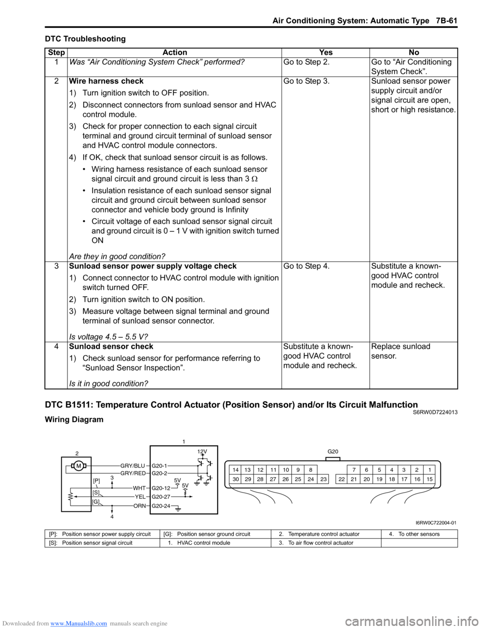
DTC B1511: Temperature Control Actuator (Position Sensor) and/or Its Circuit MalfunctionS6RW0D7224013
Wiring DiagramStep Action Yes No
1Was “Air Conditioning System Check” performed?Go to Step 2. Go to “Air Conditioning
System Check”.
2Wire harness check
1) Turn ignition switch to OFF position.
2) Disconnect connectors from sunload sensor and HVAC
control module.
3) Check for proper connection to each signal circuit
terminal and ground circuit terminal of sunload sensor
and HVAC control module connectors.
4) If OK, check that sunload sensor circuit is as follows.
• Wiring harness resistance of each sunload sensor
signal circuit and ground circuit is less than 3 Ω
• Insulation resistance of each sunload sensor signal
circuit and ground circuit between sunload sensor
connector and vehicle body ground is Infinity
• Circuit voltage of each sunload sensor signal circuit
and ground circuit is 0 – 1 V with ignition switch turned
ON
Are they in good condition?Go to Step 3. Sunload sensor power
supply circuit and/or
signal circuit are open,
short or high resistance.
3Sunload sensor power supply voltage check
1) Connect connector to HVAC control module with ignition
switch turned OFF.
2) Turn ignition switch to ON position.
3) Measure voltage between signal terminal and ground
terminal of sunload sensor connector.
Is voltage 4.5 – 5.5 V?Go to Step 4. Substitute a known-
good HVAC control
module and recheck.
4Sunload sensor check
1) Check sunload sensor for performance referring to
“Sunload Sensor Inspection”.
Is it in good condition?Substitute a known-
good HVAC control
module and recheck.Replace sunload
sensor.
G20
1 2 3 4 5 6 7 8 9 10 11 12 13 14
15 16 17 18 19 20 21 24 23 22 25 26 27 28 29 30
GRY/BLUGRY/RED
5V5V
12V
ORN
WHT
YEL
G20-12
G20-27
G20-24
G20-1G20-2
2
[P]
[S]3
4
[G]
1
I6RW0C722004-01
[P]: Position sensor power supply circuit [G]: Position sensor ground circuit 2. Temperature control actuator 4. To other sensors
[S]: Position sensor signal circuit 1. HVAC control module 3. To air flow control actuator
Page 1018 of 1556

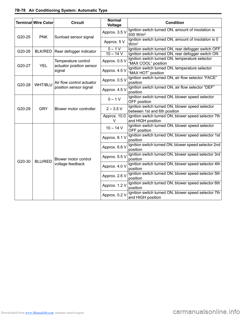
Downloaded from www.Manualslib.com manuals search engine 7B-78 Air Conditioning System: Automatic Type
G20-25 PNK Sunload sensor signalApprox. 3.5 VIgnition switch turned ON, amount of insolation is
500 W/m2
Approx. 5 VIgnition switch turned ON, amount of insolation is 0
W/m2
G20-26 BLK/RED Rear defogger indicator0 – 1 V Ignition switch turned ON, rear defogger switch OFF
10 – 14 V Ignition switch turned ON, rear defogger switch ON
G20-27 YELTemperature control
actuator position sensor
signalApprox. 0.5 VIgnition switch turned ON, temperature selector
“MAX COOL” position
Approx. 4.5 VIgnition switch turned ON, temperature selector
“MAX HOT” position
G20-28 WHT/BLUAir flow control actuator
position sensor signalApprox. 0.5 VIgnition switch turned ON, air flow selector “FACE”
position
Approx. 4.5 VIgnition switch turned ON, air flow selector “DEF”
position
G20-29 GRY Blower motor controller0 – 1 VIgnition switch turned ON, blower speed selector
OFF position
2 – 3.5 VIgnition switch turned ON, blower speed selector
between 1st and 6th position
Approx. 10.0
VIgnition switch turned ON, blower speed selector 7th
and HIGH position
G20-30 BLU/REDBlower motor control
voltage feedback10 – 14 VIgnition switch turned ON, blower speed selector
OFF position
Approx. 8.1 VIgnition switch turned ON, blower speed selector 1st
position
Approx. 6.8 VIgnition switch turned ON, blower speed selector 2nd
position
Approx. 5.5 VIgnition switch turned ON, blower speed selector 3rd
position
Approx. 4.0 VIgnition switch turned ON, blower speed selector 4th
position
Approx. 2.6 VIgnition switch turned ON, blower speed selector 5th
position
Approx. 1.2 VIgnition switch turned ON, blower speed selector 6th
position
Approx. 0.2 VIgnition switch turned ON, blower speed selector 7th
and HIGH position Terminal Wire Color CircuitNormal
Vo l ta g eCondition
Page 1025 of 1556

Downloaded from www.Manualslib.com manuals search engine Air Conditioning System: Automatic Type 7B-85
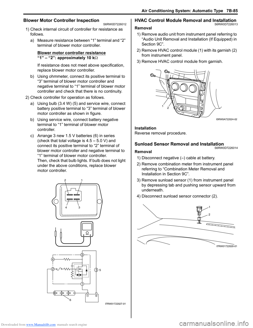
Blower Motor Controller InspectionS6RW0D7226012
1) Check internal circuit of controller for resistance as
follows.
a) Measure resistance between “1” terminal and “2”
terminal of blower motor controller.
Blower motor controller resistance
“1” – “2”: approximately 10 kΩ
If resistance does not meet above specification,
replace blower motor controller.
b) Using ohmmeter, connect its positive terminal to
“3” terminal of blower motor controller and
negative terminal to “1” terminal of blower motor
controller and check that there is no continuity.
2) Check controller for operation as follows.
a) Using bulb (3.4 W) (5) and service wire, connect
battery positive terminal to “3” terminal of blower
motor controller as shown in figure.
b) Using service wire, connect battery negative
terminal to “1” terminal of blower motor
controller.
c) Arrange 3 new 1.5 V batteries (6) in series
(check that total voltage is 4.5 – 5.0 V) and
connect its positive terminal to “2” terminal of
blower motor controller and negative terminal to
“1” terminal of blower motor controller.
Then, check that bulb lights. If bulb does not light
under the above conditions, replace blower
motor controller.
HVAC Control Module Removal and InstallationS6RW0D7226013
Removal
1) Remove audio unit from instrument panel referring to
“Audio Unit Removal and Installation (If Equipped) in
Section 9C”.
2) Remove HVAC control module (1) with its garnish (2)
from instrument panel.
3) Remove HVAC control module from garnish.
Installation
Reverse removal procedure.
Sunload Sensor Removal and InstallationS6RW0D7226014
Removal
1) Disconnect negative (–) cable at battery.
2) Remove combination meter from instrument panel
referring to “Combination Meter Removal and
Installation in Section 9C”.
3) Remove sunload sensor (1) from instrument panel
by depressing tab and pushing sensor upward from
underneath.
4) Disconnect sunload sensor connector (2).
21
43
3
1 2 4
5
6I7RW01722027-01
12
I5RW0A722024-02
1
2
I7RW01722028-01
Page 1026 of 1556

Downloaded from www.Manualslib.com manuals search engine 7B-86 Air Conditioning System: Automatic Type
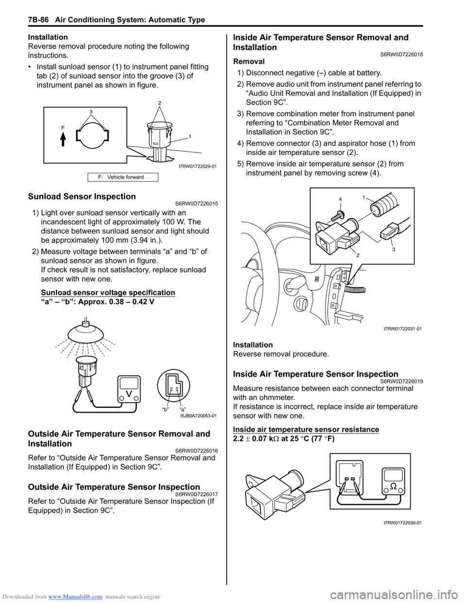
Installation
Reverse removal procedure noting the following
instructions.
• Install sunload sensor (1) to instrument panel fitting
tab (2) of sunload sensor into the groove (3) of
instrument panel as shown in figure.
Sunload Sensor InspectionS6RW0D7226015
1) Light over sunload sensor vertically with an
incandescent light of approximately 100 W. The
distance between sunload sensor and light should
be approximately 100 mm (3.94 in.).
2) Measure voltage between terminals “a” and “b” of
sunload sensor as shown in figure.
If check result is not satisfactory, replace sunload
sensor with new one.
Sunload sensor voltage specification
“a” – “b”: Approx. 0.38 – 0.42 V
Outside Air Temperature Sensor Removal and
Installation
S6RW0D7226016
Refer to “Outside Air Temperature Sensor Removal and
Installation (If Equipped) in Section 9C”.
Outside Air Temperature Sensor InspectionS6RW0D7226017
Refer to “Outside Air Temperature Sensor Inspection (If
Equipped) in Section 9C”.
Inside Air Temperature Sensor Removal and
Installation
S6RW0D7226018
Removal
1) Disconnect negative (–) cable at battery.
2) Remove audio unit from instrument panel referring to
“Audio Unit Removal and Installation (If Equipped) in
Section 9C”.
3) Remove combination meter from instrument panel
referring to “Combination Meter Removal and
Installation in Section 9C”.
4) Remove connector (3) and aspirator hose (1) from
inside air temperature sensor (2).
5) Remove inside air temperature sensor (2) from
instrument panel by removing screw (4).
Installation
Reverse removal procedure.
Inside Air Temperature Sensor InspectionS6RW0D7226019
Measure resistance between each connector terminal
with an ohmmeter.
If resistance is incorrect, replace inside air temperature
sensor with new one.
Inside air temperature sensor resistance
2.2 ± 0.07 kΩ at 25 °C (77 °F)
F: Vehicle forward
2
F
1
3
I7RW01722029-01
“b” “a”I5JB0A720053-01
1
23 4
I7RW01722031-01
I7RW01722030-01