2006 SUZUKI SX4 Starter
[x] Cancel search: StarterPage 192 of 1556

Downloaded from www.Manualslib.com manuals search engine 1A-142 Engine General Information and Diagnosis:
DTC Troubleshooting
NOTE
Before this troubleshooting is performed, read the precautions for DTC troubleshooting referring to
“Precautions for DTC Troubleshooting”.
Step Action Yes No
1Was “Engine and Emission Control System Check”
performed?Go to Step 2. Go to “Engine and
Emission Control
System Check”.
2Starter signal check
1) Turn OFF ignition switch.
2) Remove ECM from its bracket with ECM connectors
connected.
3) Start engine, measure voltage between “C01-48”
terminal of ECM connector and vehicle body ground.
Is voltage 0 – 1 V?Intermittent trouble.
Check for intermittent
referring to “Intermittent
and Poor Connection
Inspection in Section
00”. If OK, substitute a
known-good ECM and
recheck.Go to Step 3.
3Wire circuit check
1) Disconnect starting motor control relay in individual
circuit fuse box No.1 with ignition switch turned OFF.
2) Check for proper connection to starting motor control
relay at “RED/WHT”, “RED”, “WHT”, and “YEL/GRN”
wire terminals.
3) Disconnect connector from starting motor.
4) Measure voltage between “C01-48” terminal of ECM
connector and vehicle body ground with ignition switch
turned ON.
Is voltage 0 – 1 V?Go to Step 4. “YEL/GRN” wire is
shorted to power circuit.
If wires are OK,
substitute a known-
good ECM and recheck.
4Wire circuit check
1) Measure voltage between “RED/WHT” wire terminal of
starting motor control relay connector and vehicle body
ground with ignition switch turned ON.
Is voltage 0 – 1 V?Check starting motor
control relay. If OK,
substitute a known-
good ECM and recheck.Faulty ignition switch,
check ignition switch
referring to “Ignition
Switch Inspection in
Section 9C”.
If ignition switch is OK,
check for short circuit
between ignition switch
and starting motor
control relay to power
circuit.
Page 406 of 1556

Downloaded from www.Manualslib.com manuals search engine 1I-1 Starting System:
Engine
Starting System
Schematic and Routing Diagram
Cranking System Circuit DiagramS6RW0D1902001
Diagnostic Information and Procedures
Cranking System Symptom DiagnosisS6RW0D1904001
Possible symptoms due to starting system trouble would be as follows:
• Starting motor does not run (or runs slowly)
• Starting motor runs but fails to crank engine
• Abnormal noise is heard
Proper diagnosis must be made to determine exactly where the cause of each trouble lies in battery, wiring harness,
(including starting motor switch), starting motor or engine.
Do not remove motor just because starting motor does not run. Check the following items and narrow down scope of
possible causes.
1) Condition of trouble
2) Tightness of battery terminals (including ground cable connection on engine side) and starting motor terminals
3) Discharge of battery
4) Mounting of starting motor
I4RS0A190001-01
1. Pinion drive lever 6. Magnetic switch contacts 11. Ignition & Starter switch
2. Pinion & Over-running clutch 7. Pull-in coil 12. Battery
3. Magnetic switch 8. Starting motor 13. To ECM
4. Hold-in coil 9. Starting motor control relay
5. Plunger 10. A/T: Transmission range sensor (shift switch)
Page 408 of 1556

Downloaded from www.Manualslib.com manuals search engine 1I-3 Starting System:
Cranking System TestS6RW0D1904002
CAUTION!
Each test must be performed within 3 – 5
seconds to avoid coil from burning.
Pull-In Test
Connect battery to the magnetic switch as shown.
Check that plunger and pinion move outward.
If plunger and pinion don’t move, replace the magnetic
switch.
NOTE
Before testing, disconnect lead wire from
terminal “M” (2).
Hold-In Test
While connected as the figure with plunger out,
disconnect negative lead from terminal “M”.
Check that plunger and pinion remain out.
If plunger and pinion return inward, replace the magnetic
switch.Plunger and Pinion Return Test
Disconnect negative lead from starting motor body.
Check that plunger and pinion return inward.
If plunger and pinion don’t return, replace the magnetic
switch.
No-Load Performance Test
Connect battery and ammeter to starter as shown.
Check that starter rotates smoothly and steadily with
pinion moving out. Check that ammeter indicates
specified current.
Specified current (No-load performance test)
90 A MAX. at 11 V Starting motor does not
stop runningFused contact points of magnetic switchReplace magnetic switch.
Short-circuit between turns of magnetic
switch coil (layer short-circuit)Replace magnetic switch.
Failure of returning action in ignition
switchReplace. Condition Possible cause Correction / Reference Item
1. Terminal “S”
3. Lead wire (switch to motor)
I2RH01190002-01
I2RH01190003-01
I2RH01190004-01
I2RH01190005-01
Page 658 of 1556

Downloaded from www.Manualslib.com manuals search engine 5A-10 Automatic Transmission/Transaxle:
Schematic and Routing Diagram
Transmission Control Module (TCM) Wiring DiagramS6RW0D5102001
12V
12V
12V
IG1
118
9
10
P
R
N
D
2
L12
2.5V
5V
12V
5V
12V
12V
12V
WHT
BLK
BLK
BLK
BLK
PPLBLK/WHT
BLK/ORN
IG11
RED/BLK
YEL/BLKYEL/BLU
LT GRN/BLK
+BB
WHT/RED
14
20 15
16
17
19
12V18
1 2
3
132126
24 27
28
29
30
65
16 15 14 13 12 1143
24 23 212210 9 8 721
19 20 18 17 C06
17 16
26 2515 14 65 342
13 12
23 22 2411 10 9
21 20 1987
18 1 C07
[A]
22
25
YELYEL/GRN
WHT
P
N
BRN LT/GRN
ORN
BLK/YEL
BLU/BLK
GRY
LT GRN/BLKWHT/BLU
WHT/BLK
C06-11
C06-12
C06-16
C06-15
C06-14
C06-4
C06-2
C06-1
C06-23C06-6 C06-24C06-5
C06-3
RED
GRN GRN/ORNPNK/BLK
GRN/YEL
LT GRN/BLKC07-6
C07-16
C07-23 C07-25
C07-20
C07-1
C07-8
C07-7
C07-19
C07-18
4IG11 23
C07-9
YEL
RED
WHTBLU35 34
3637
5REDWHT
7
WHT
RED
33
4
6
C06-7C06-17WHT
REDREDWHT
WHT
12V12V
WHTRED
WHTREDREDWHT
31
32
RED
WHTRED[B]
[C]
I6RW0D510003-02
1. TCM 15. Shift solenoid valve-A (No.1) 29. “ST SIG” fuse
2. Input shaft speed sensor 16. Shift solenoid valve-B (No.2) 30. “ST” fuse
3. Output shaft speed sensor / VSS 17. Timing solenoid valve 31. MIL
4. ECM 18. TCC solenoid valve 32. Transmission warning light (non-Euro-OBD model)
5. Combination meter 19. Pressure control solenoid valve 33. ABS control module
6. BCM 20. A/T 34. To Data link connector
7. 4WD control module (if equipped) 21. A/T relay 35. To BCM
8. “3” position switch 22. Inhibitor switch (including transmission range
sensor)36. Junction connector
9. Shift lock solenoid 23. Starter motor relay 37. Keyless start control module (if equipped)
10. Brake light switch 24. Ignition switch [A]: Terminal arrangement of TCM connector (viewed
from harness side)
11. Transmission range sensor 25. Starter motor [B]: Junction block with BCM model
12. Backup lamp 26. “DOME” fuse [C]: Junction block without BCM model
13. Data link connector (DLC) 27. “AT” fuse
14. Transmission fluid temperature sensor 28. “IG1 SIG” fuse
Page 749 of 1556

Downloaded from www.Manualslib.com manuals search engine Automatic Transmission/Transaxle: 5A-101
Remounting
1) Make sure that torque converter is installed correctly
to transaxle.
Refer to “Automatic Transaxle Unit Assembly”.
2) Attach transaxle to engine. Tighten engine oil pan
bolts (1) to specified torque.
WARNING!
Be sure to keep transaxle with torque
converter horizontal or facing up throughout
the work. Should it be tilted with torque
converter down, converter may fall off and
cause personal injury.
Tightening torque
Engine oil pan bolt (a): 55 N·m (5.5 kgf-m, 40.0
lb-ft)
Transaxle and engine fastening bolt (b): 85 N·m
(8.5 kgf-m, 61.5 lb-ft)
Transaxle and engine fastening nut (c): 85 N·m (
8.5 kgf-m, 61.5 lb-ft)3) Tighten drive plate to torque converter bolts. Align
bolt hole of drive plate and torque converter then
tighten bolts through torque converter housing lower
plate opening.
Lock drive plate (1) by engaging flat head rod or the
like (2) with drive plate gear.
Tightening torque
Drive plate to torque converter bolt (a): 19 N·m (
1.9 kgf-m, 14.0 lb-ft)
4) Install transaxle housing lower plate (1).
Tightening torque
Transaxle housing lower plate bolt (a): 11 N·m (
1.1 kgf-m, 8.0 lb-ft)
5) Install starter motor referring to “Starting Motor
Dismounting and Remounting in Section 1I”.
6) Remount engine with transaxle assembly to vehicle.
Refer to “Engine Assembly Removal and Installation
in Section 1D” for its procedure.
2, (b)
2, (b)
1, (a)
3, (c)I5RW0C510054-01
3. Engine oil pan
1
(a)
(a)3
2
I5RW0C510055-01
1 (a)
I5RW0C510056-01
Page 1168 of 1556

Downloaded from www.Manualslib.com manuals search engine 9A-1 Wiring Systems:
Body, Cab and Accessories
Wiring Systems
Precautions
Cautions in Body Electrical System ServicingS6RW0D9100001
When servicing the electric systems, observe the cautions described in “Air Bag Warning in Section 00” to protect
electrical parts and to prevent a fire.
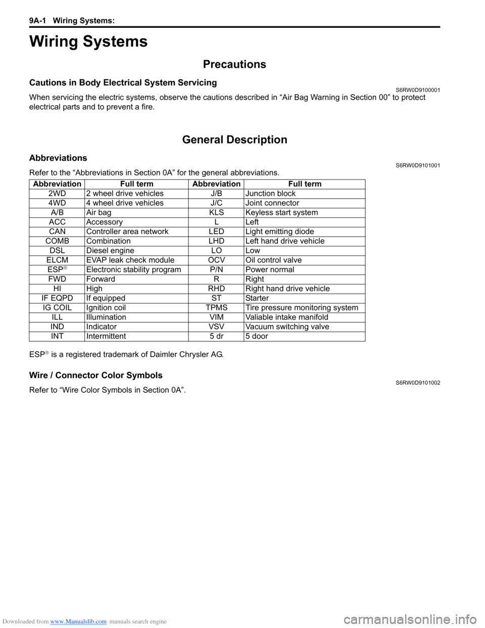
General Description
AbbreviationsS6RW0D9101001
Refer to the “Abbreviations in Section 0A” for the general abbreviations.
ESP
® is a registered trademark of Daimler Chrysler AG.
Wire / Connector Color SymbolsS6RW0D9101002
Refer to “Wire Color Symbols in Section 0A”. Abbreviation Full term Abbreviation Full term
2WD 2 wheel drive vehicles J/B Junction block
4WD 4 wheel drive vehicles J/C Joint connector
A/B Air bag KLS Keyless start system
ACC Accessory L Left
CAN Controller area network LED Light emitting diode
COMB Combination LHD Left hand drive vehicle
DSL Diesel engine LO Low
ELCM EVAP leak check module OCV Oil control valve
ESP
®Electronic stability program P/N Power normal
FWD Forward R Right
HI High RHD Right hand drive vehicle
IF EQPD If equipped ST Starter
IG COIL Ignition coil TPMS Tire pressure monitoring system
ILL Illumination VIM Valiable intake manifold
IND Indicator VSV Vacuum switching valve
INT Intermittent 5 dr 5 door
Page 1510 of 1556

Downloaded from www.Manualslib.com manuals search engine 10C-8 Immobilizer Control System:
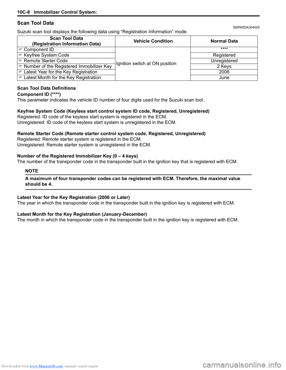
Scan Tool DataS6RW0DA304005
Suzuki scan tool displays the following data using “Registration Information” mode.
Scan Tool Data Definitions
Component ID (****)
This parameter indicates the vehicle ID number of four digits used for the Suzuki scan tool.
Keyfree System Code (Keyless start control system ID code, Registered, Unregistered)
Registered: ID code of the keyless start system is registered in the ECM.
Unregistered: ID code of the keyless start system is unregistered in the ECM.
Remote Starter Code (Remote starter control system code, Registered, Unregistered)
Registered: Remote starter system is registered in the ECM.
Unregistered: Remote starter system is unregistered in the ECM.
Number of the Registered Immobilizer Key (0 – 4 keys)
The number of the transponder code in the transponder built in the ignition key that is registered with ECM.
NOTE
A maximum of four transponder codes can be registered with ECM. Therefore, the maximal value
should be 4.
Latest Year for the Key Registration (2006 or Later)
The year in which the transponder code in the transponder built in the ignition key is registered with ECM.
Latest Month for the Key Registration (January-December)
The month in which the transponder code in the transponder built in the ignition key is registered with ECM. Scan Tool Data
(Registration Information Data)Vehicle Condition Normal Data
�) Component ID
Ignition switch at ON position****
�) Keyfree System Code Registered
�) Remote Starter Code Unregistered
�) Number of the Registered Immobilizer Key 2 Keys
�) Latest Year for the Key Registration 2006
�) Latest Month for the Key Registration June