2006 SUZUKI SX4 IMMOBILIZER CONTROL MODULE in ECM
[x] Cancel search: IMMOBILIZER CONTROL MODULE in ECMPage 68 of 1556

Downloaded from www.Manualslib.com manuals search engine 1A-18 Engine General Information and Diagnosis:
Engine and Emission Control Input / Output TableS6RW0D1101010
INPUTOUTPUT
ELECTRIC CONTROL DEVICE
BAROMETRIC PRESSURE SENSOR
BRAKE LIGHT SWITCH
START SWITCH
IGNITION SWITCH
A/C REFRIGERANT PRESSURE SENSOR (if equipped with A/C)
BLOWER SWITCH
A/C SWITCH (if equipped with A/C)
A/C EVAP OUTLET AIR TEMP. SENSOR (if equipped with A/C)
WHEEL SPEED SENSOR
HEATED OXYGEN SENSOR-1
HEATED OXYGEN SENSOR-2 (if equipped)
IAT SENSOR OF MAF AND IAT SENSOR MAF SENSOR OF MAF AND IAT SENSOR
ECT SENSOR
TP SENSOR
THROTTLE ACTUATOR
A/C CONDENSER FAN RELAY FUEL PUMP RELAY
FUEL INJECT
THROTTLE ACTUATOR CONTROL RELAYOR
HO2S HEATER
IGNITION COIL WITH IGNITER
EGR VALVE (if equipped)
EVAP CANISTER PURGE VALVEA/C COMPRESSOR RELAY (if equipped with A/C)RADIATOR FAN RELAY
MIL
MAIN RELAY
OIL CONTROL VALVE (for engine with VVT system) SIGNAL FROM SENSOR, SWITCH AND CONTROL MODULE
ABS CONTROL MODULE
KNOCK SENSOR
MAP SENSOR (if equipped)
CMP SENSOR
CKP SENSOR
IMMOBILIZER CONTROL MODULE (in ECM)
ELECTRIC LOAD (head light, rear defogger
TCM (for A/T model
P/S CONTROL MODULE))
APP SENSOR
I6RW0D110015-03
Page 70 of 1556

Downloaded from www.Manualslib.com manuals search engine 1A-20 Engine General Information and Diagnosis:
1. Air cleaner 17. Radiator cooling fan 33. A/C switch (A/C model)
2. EVAP canister purge valve 18. A/C condenser cooling fan 34. A/C evaporator outlet air temp. sensor (manual A/C
model)
3. MAF and IAT sensor 19. Combination meter 35. Immobilizer coil antenna
4. TP sensor 20. BCM 36. Main relay
5. MAP sensor (if equipped) 21. Ignition switch37. Wheel speed sensor (VSS) (for M/T model)
6. EGR valve (if equipped) 22. Starter magnetic switch 38. Oil control valve
7. EVAP canister 23. Heated oxygen sensor (HO2S)-2 (if
equipped)39. ABS control module
8. Tank pressure control valve (built-in fuel pump) 24. DLC 40. Starting motor control relay
9. Fuel pump (with pressure regulator) 25. Electric load 41. A/C refrigerant pressure sensor (A/C model)
10. Ignition coil assembly 26. Fuel level sensor 42. APP sensor
11. Fuel injector 27. Brake light 43. Throttle actuator control relay
12. Heated oxygen sensor (HO2S)-1 28. Brake light switch 44. Throttle actuator
13. Knock sensor 29. ECM 45. TCM (for A/T model)
14. ECT sensor 30. Barometric pressure sensor 46. Output shaft speed sensor (VSS) (for A/T model)
15. CMP sensor 31. Battery
16. CKP sensor 32. A/C compressor relay (A/C model)
Page 877 of 1556

Downloaded from www.Manualslib.com manuals search engine Steering Wheel and Column: 6B-8
3) Align flat part “a” of steering lower shaft (1) with bolt
hole “b” of shaft joint (2) of column as shown. Then
insert lower shaft into shaft joint of steering column.
4) Tighten lower shaft upper joint bolt (3) to specified
torque.
CAUTION!
After tightening column nuts, tighten steering
shaft upper joint bolt. Otherwise, shaft joint
bearing is damaged.
Tightening torque
Steering lower shaft assembly upper joint bolt
(a): 25 N·m (2.5 kgf-m, 18.5 lb-ft)
5) Install lighting switch and wiper switch to steering
column.
6) (Immobilizer model)
Install immobilizer control module from steering
column, referring to “ICM Removal and Installation in
Section 10C”.
7) Install contact coil cable assembly and steering
wheel referring to “Contact Coil Cable Assembly
Removal and Installation” and “Steering Wheel
Removal and Installation”.
8) Connect negative (–) cable to battery.
9) Enable air bag system referring to “Enabling Air Bag
System in Section 8B”.
Steering Column InspectionS6RW0D6206009
Check steering column for damage and operation
referring to “Checking Steering Column for Accident
Damage”.
Ignition Switch Cylinder Assembly Removal
and Installation (Non- Keyless Start Model)
S6RW0D6206010
Removal
1) Disconnect negative (–) cable at battery.
2) Disable air bag system referring to “Disabling Air
Bag System in Section 8B”.
3) Remove steering column upper and lower covers.
4) (Immobilizer model)
Remove immobilizer control module referring to
“ICM Removal and Installation in Section 10C”.
5) Remove ignition switch cylinder assembly as follows.
a) Turn ignition key to “ACC” position.
b) Insert 2 mm (0.078 in.) rod (2) through hole (3)
and push ignition switch cylinder lock.
c) Detach ignition switch cylinder assembly (1) from
steering lock assembly (4).
Installation
1) Install ignition switch cylinder assembly as follows.
a) Turn ignition key to “ACC” position.
b) In this state, push ignition switch cylinder
assembly into steering lock assembly till it clicks.
2) (Immobilizer model)
Install immobilizer control module referring to “ICM
Removal and Installation in Section 10C”.
3) Install upper and lower cover and screws.
4) Connect negative (–) cable to battery.
5) Enabling air bag system referring to “Enabling Air
Bag System in Section 8B”.
6) (Immobilizer model)
If ignition switch cylinder assembly (that is ignition
key) has replaced, register ignition key transponder
code to ECM referring to “Registration of the Ignition
Key in Section 10C”.
1 2
“a”“b”
3, (a)
I5RW0A620007-01
2
3
1
4
I5JB0A620025-01
Page 878 of 1556

Downloaded from www.Manualslib.com manuals search engine 6B-9 Steering Wheel and Column:
Steering Lock Assembly (Ignition Switch)
Removal and Installation
S6RW0D6206011
Removal
1) Remove steering column. Refer to “Steering Column
Removal and Installation”.
2) Using center punch (1), loosen and remove steering
lock mounting bolts (2).
NOTE
Use care not to damage aluminum part of
steering lock body with center punch.
3) Turn ignition key to “ACC” or “ON” position and
remove steering lock assembly from steering
column.Installation
1) Position oblong hole (1) of steering shaft (2) in the
center of hole (3) in column (4).
2) Turn ignition key to “ACC” or “ON” position and
install steering lock assembly (5) onto column (4).
3) Now turn ignition key to “LOCK” position and pull it
out.
4) Align hub on lock with oblong hole (1) of steering
shaft (2) and rotate shaft to assure that steering shaft
is locked.
5) Tighten new bolts (1) until head of each bolt is
broken off.
6) Turn ignition key to “ACC” or “ON” position and
check to be sure that steering shaft (2) rotates
smoothly. Also check for lock operation.
7) Install steering column. Refer to “Steering Column
Removal and Installation”.
8) (Keyless start model)
If steering lock assembly has replaced, after
completing installation, register steering lock unit ID
code to keyless start control module as following.
• Immobilizer model:
Register ignition key transponder code in ECM
referring to “Registration of the Ignition Key in
Section 10C”.
• Non-immobilizer model:
Register steering lock unit ID code in keyless start
control module referring to “Keyless Start
Registration in Section 10E”.
I4RS0B620005-02
1
32
4
5
I4RS0B620006-02
I4RS0B620007-02
Page 1354 of 1556

Downloaded from www.Manualslib.com manuals search engine 9C-2 Instrumentation / Driver Info. / Horn:
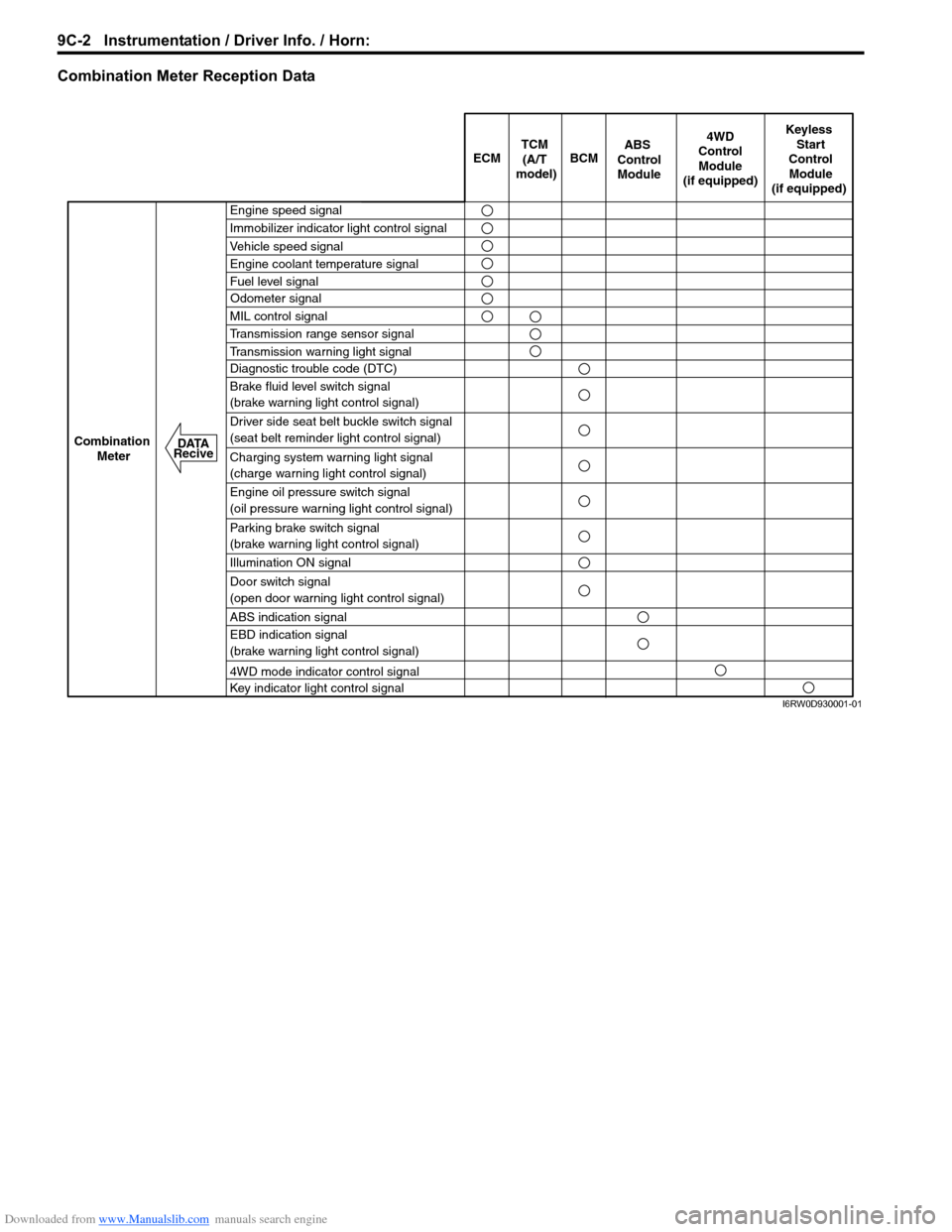
Combination Meter Reception Data
ECM BCM
Keyless
Start
Control
Module
(if equipped)
Combination
Meter4WD
Control
Module
(if equipped)TCM
(A/T
model)
Engine speed signal
Immobilizer indicator light control signal
Vehicle speed signal
Engine coolant temperature signal
Fuel level signal
MIL control signal
Transmission range sensor signal
Transmission warning light signal
Diagnostic trouble code (DTC)
Brake fluid level switch signal
(brake warning light control signal)
Driver side seat belt buckle switch signal
(seat belt reminder light control signal)
Charging system warning light signal
(charge warning light control signal)
Engine oil pressure switch signal
(oil pressure warning light control signal)
Parking brake switch signal
(brake warning light control signal)
Illumination ON signal
Door switch signal
(open door warning light control signal)
ABS indication signal
EBD indication signal
(brake warning light control signal)
4WD mode indicator control signal
Key indicator light control signal
ABS
Control
Module
Odometer signal
DATA
Recive
I6RW0D930001-01
Page 1471 of 1556

Downloaded from www.Manualslib.com manuals search engine Table of Contents 10- i
10
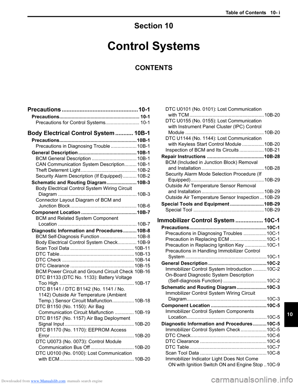
Section 10
CONTENTS
Control Systems
Precautions ............................................... 10-1
Precautions........................................................... 10-1
Precautions for Control Systems......................... 10-1
Body Electrical Control System ........... 10B-1
Precautions......................................................... 10B-1
Precautions in Diagnosing Trouble ................... 10B-1
General Description ........................................... 10B-1
BCM General Description ................................. 10B-1
CAN Communication System Description......... 10B-1
Theft Deterrent Light ......................................... 10B-2
Security Alarm Description (If Equipped) .......... 10B-2
Schematic and Routing Diagram ...................... 10B-3
Body Electrical Control System Wiring Circuit
Diagram .......................................................... 10B-3
Connector Layout Diagram of BCM and
Junction Block ................................................. 10B-6
Component Location ......................................... 10B-7
BCM and Related System Component
Location .......................................................... 10B-7
Diagnostic Information and Procedures .......... 10B-8
BCM Self-Diagnosis Function ........................... 10B-8
Body Electrical Control System Check.............. 10B-9
Scan Tool Data ............................................... 10B-11
DTC Table ....................................................... 10B-13
DTC Check ..................................................... 10B-14
DTC Clearance ............................................... 10B-15
BCM Power Circuit and Ground Circuit Check 10B-16
DTC B1133 (DTC No. 1133): Battery Voltage
Too High ....................................................... 10B-17
DTC B1141 / DTC B1142 (No. 1141 / No.
1142) Outside Air Temperature (Ambient
Temp.) Sensor Circuit Malfunction ................ 10B-18
DTC B1150 (No. 1150): Air Bag
Communication Circuit Malfunction .............. 10B-19
DTC B1157 (No. 1157) Air Bag Deployment
Signal Input ................................................... 10B-20
DTC B1170 (No. 1170): EEPROM Access
Error .............................................................. 10B-20
DTC U0073 (No. 0073): Control Module
Communication Bus Off ................................ 10B-20
DTC U0100 (No. 0100): Lost Communication
with ECM....................................................... 10B-20DTC U0101 (No. 0101): Lost Communication
with TCM ....................................................... 10B-20
DTC U0155 (No. 0155): Lost Communication
with Instrument Panel Cluster (IPC) Control
Module .......................................................... 10B-20
DTC U1144 (No. 1144): Lost Communication
with Keyless Start Control Module ................ 10B-20
Inspection of BCM and Its Circuits .................. 10B-21
Repair Instructions ..........................................10B-28
BCM (Included in Junction Block) Removal
and Installation .............................................. 10B-28
Security Alarm Mode Selection Procedure (If
Equipped) ...................................................... 10B-29
Outside Air Temperature Sensor Removal
and Installation .............................................. 10B-29
Outside Air Temperature Sensor Inspection ... 10B-29
Special Tools and Equipment .........................10B-29
Special Tool .................................................... 10B-29
Immobilizer Control System ................. 10C-1
Precautions.........................................................10C-1
Precautions in Diagnosing Troubles .................10C-1
Precaution in Replacing ECM ...........................10C-1
Precaution in Replacing Ignition Key ................10C-1
Precautions in Handling Immobilizer Control
System ............................................................10C-1
General Description ...........................................10C-2
Immobilizer Control System Introduction ..........10C-2
On-Board Diagnostic System Description
(Self-diagnosis Function)................................10C-2
Schematic and Routing Diagram ......................10C-3
Immobilizer Control System Wiring Circuit
Diagram...........................................................10C-3
Component Location .........................................10C-5
Immobilizer Control System Components
Location...........................................................10C-5
Diagnostic Information and Procedures ..........10C-5
Immobilizer Control System Check ...................10C-5
DTC Check........................................................10C-6
DTC Clearance .................................................10C-6
DTC Table .........................................................10C-7
Scan Tool Data .................................................10C-8
Immobilizer Indicator Light Does Not Come
ON with Ignition Switch ON and Engine Stop ..10C-9
Page 1472 of 1556

Downloaded from www.Manualslib.com manuals search engine 10-ii Table of Contents
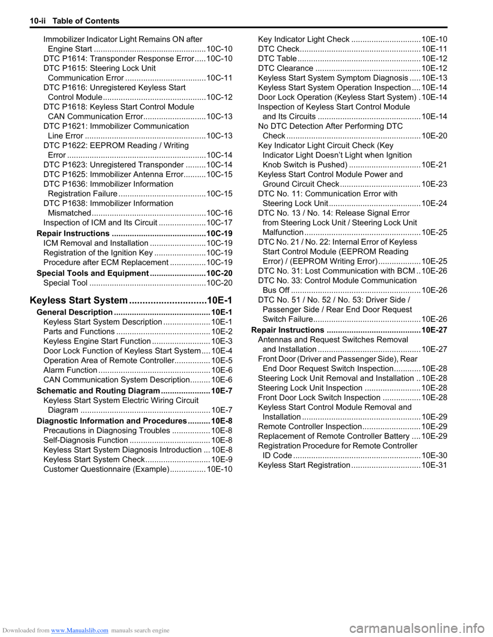
Immobilizer Indicator Light Remains ON after
Engine Start ..................................................10C-10
DTC P1614: Transponder Response Error .....10C-10
DTC P1615: Steering Lock Unit
Communication Error ....................................10C-11
DTC P1616: Unregistered Keyless Start
Control Module ..............................................10C-12
DTC P1618: Keyless Start Control Module
CAN Communication Error............................10C-13
DTC P1621: Immobilizer Communication
Line Error ......................................................10C-13
DTC P1622: EEPROM Reading / Writing
Error ..............................................................10C-14
DTC P1623: Unregistered Transponder .........10C-14
DTC P1625: Immobilizer Antenna Error..........10C-15
DTC P1636: Immobilizer Information
Registration Failure .......................................10C-15
DTC P1638: Immobilizer Information
Mismatched ...................................................10C-16
Inspection of ICM and Its Circuit .....................10C-17
Repair Instructions ..........................................10C-19
ICM Removal and Installation .........................10C-19
Registration of the Ignition Key .......................10C-19
Procedure after ECM Replacement ................10C-19
Special Tools and Equipment .........................10C-20
Special Tool ....................................................10C-20
Keyless Start System .............................10E-1
General Description ........................................... 10E-1
Keyless Start System Description ..................... 10E-1
Parts and Functions .......................................... 10E-2
Keyless Engine Start Function .......................... 10E-3
Door Lock Function of Keyless Start System .... 10E-4
Operation Area of Remote Controller................ 10E-5
Alarm Function .................................................. 10E-6
CAN Communication System Description......... 10E-6
Schematic and Routing Diagram ...................... 10E-7
Keyless Start System Electric Wiring Circuit
Diagram .......................................................... 10E-7
Diagnostic Information and Procedures .......... 10E-8
Precautions in Diagnosing Troubles ................. 10E-8
Self-Diagnosis Function .................................... 10E-8
Keyless Start System Diagnosis Introduction ... 10E-8
Keyless Start System Check ............................. 10E-9
Customer Questionnaire (Example) ................ 10E-10Key Indicator Light Check ............................... 10E-10
DTC Check...................................................... 10E-11
DTC Table ....................................................... 10E-12
DTC Clearance ............................................... 10E-12
Keyless Start System Symptom Diagnosis ..... 10E-13
Keyless Start System Operation Inspection .... 10E-14
Door Lock Operation (Keyless Start System) . 10E-14
Inspection of Keyless Start Control Module
and Its Circuits .............................................. 10E-14
No DTC Detection After Performing DTC
Check ............................................................ 10E-20
Key Indicator Light Circuit Check (Key
Indicator Light Doesn’t Light when Ignition
Knob Switch is Pushed) ................................ 10E-21
Keyless Start Control Module Power and
Ground Circuit Check .................................... 10E-23
DTC No. 11: Communication Error with
Steering Lock Unit ......................................... 10E-24
DTC No. 13 / No. 14: Release Signal Error
from Steering Lock Unit / Steering Lock Unit
Malfunction .................................................... 10E-25
DTC No. 21 / No. 22: Internal Error of Keyless
Start Control Module (EEPROM Reading
Error) / (EEPROM Writing Error) ................... 10E-25
DTC No. 31: Lost Communication with BCM .. 10E-26
DTC No. 33: Control Module Communication
Bus Off .......................................................... 10E-26
DTC No. 51 / No. 52 / No. 53: Driver Side /
Passenger Side / Rear End Door Request
Switch Failure................................................ 10E-26
Repair Instructions .......................................... 10E-27
Antennas and Request Switches Removal
and Installation .............................................. 10E-27
Front Door (Driver and Passenger Side), Rear
End Door Request Switch Inspection............ 10E-28
Steering Lock Unit Removal and Installation .. 10E-28
Steering Lock Unit Inspection ......................... 10E-28
Front Door Lock Switch Inspection ................. 10E-28
Keyless Start Control Module Removal and
Installation ..................................................... 10E-29
Remote Controller Inspection.......................... 10E-29
Replacement of Remote Controller Battery .... 10E-29
Registration Procedure for Remote Controller
ID Code ......................................................... 10E-30
Keyless Start Registration ............................... 10E-31
Page 1503 of 1556

Downloaded from www.Manualslib.com manuals search engine Immobilizer Control System: 10C-1
Control Systems
Immobilizer Control System
Precautions
Precautions in Diagnosing TroublesS6RW0DA300001
• Before confirming the diagnostic trouble code (DTC),
do not disconnect connector from ECM, battery cable
from battery, ground wire harness, or main fuse. Such
disconnection will erase DTC stored in ECM.
• DTC stored in ECM memory can be checked as well
as cleared by using SUZUKI scan tool. Before using
SUZUKI scan tool, read its operator’s manual
carefully to know how to use it and what functions are
available.
• Be sure to read “Precautions for Electrical Circuit
Service in Section 00” before inspection.
• Communication of ECM, BCM, ABS control module,
TCM (if equipped), 4WD control module (if equipped),
keyless start control module (if equipped),
combination meter and DLC is established by CAN
(Controller Area Network). Therefore, handle CAN
communication lines with care referring to “Precaution
for CAN Communication System in Section 00”.
For CAN communication system, refer to description
on “CAN Communication System Description in
Section 1A”.
Precaution in Replacing ECMS6RW0DA300002
• If ECM is replaced with new or used one without
Immobilizer control function, the engine will not be
started. In case of the above, check if the newly
installed ECM has Immobilizer control function.
• After ECM is replaced with new one or used one, the
transponder code in the transponder built in the
ignition key has to be registered with ECM. Or, the
engine cannot be started up. For the registration
procedure, refer to “Procedure after ECM
Replacement”.
Precaution in Replacing Ignition KeyS6RW0DA300003
To register ignition key in case of replacing key(s) and/or
making spare key(s), the transponder code in the ignition
key is registered with ECM. Or the engine can not be
started up. For the registration procedure, refer to
“Registration of the Ignition Key”.
Precautions in Handling Immobilizer Control
System
S6RW0DA300004
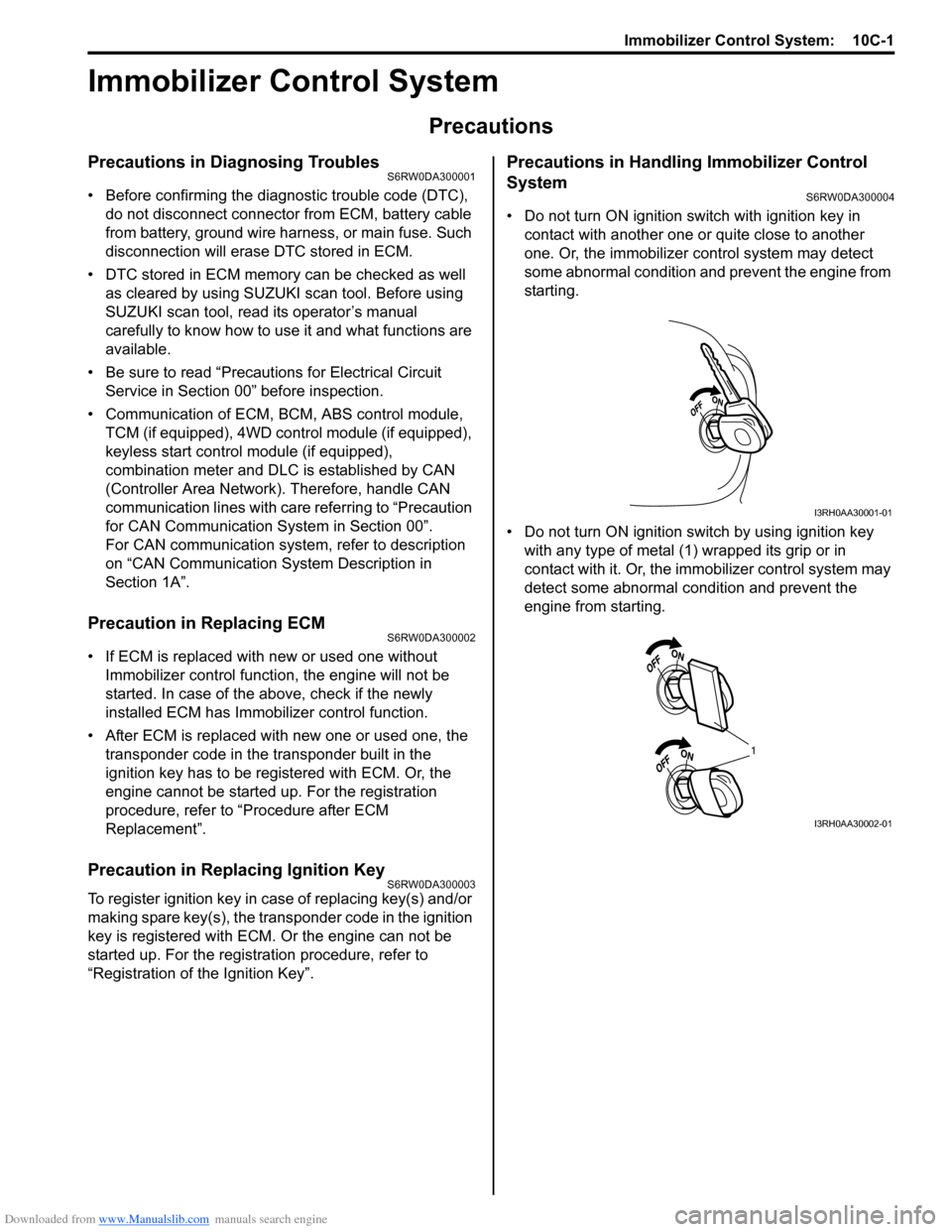
• Do not turn ON ignition switch with ignition key in
contact with another one or quite close to another
one. Or, the immobilizer control system may detect
some abnormal condition and prevent the engine from
starting.
• Do not turn ON ignition switch by using ignition key
with any type of metal (1) wrapped its grip or in
contact with it. Or, the immobilizer control system may
detect some abnormal condition and prevent the
engine from starting.
I3RH0AA30001-01
1
I3RH0AA30002-01