Page 1283 of 1556
Downloaded from www.Manualslib.com manuals search engine Wiring Systems: 9A-116
D-4 Illumination Light System Circuit Diagram (Taiwan)S6RW0D910E025
BLU/WHT
RED/YEL
10ATAIL
36
J/B
12G272
10
G14413
131721
RED/YELRED/YEL
RED/YELRED/YELRED/YEL
L3143
BLKBLK
BLKBLK
"D-3"
A/T
RY
Switch
J/C
G306
RED/YEL
RY
RED/YEL
Switch
Auto
unit
RY
RED/YEL
Mode control
switch
"E-1"Tail light
(R)
"D-2"
"E-2"
"D-6"
OFF
TAIL
HEAD+BT T
P
187
RY
RED/YEL
Audio
"G-1"
D
D
D D D
RY
RED/YEL
D
RED/YEL
Multi
information
display
"G-2"
RED/YEL
RYRY
RYRY
RY
Tail light (L)
"D-2"Front
position
light
"D-2"
Licence plate
light
"D-2"
RED/YEL
RED/YEL
E32516
RY
RY
J/C
B
BL348
J/C
C
CL346
A/T
shift
lever
L1012
5
2 1
3
4
Tail light
relay
11
G05
G0412
BCM
I6RW0C910985-01
Page 1326 of 1556

Downloaded from www.Manualslib.com manuals search engine 9B-7 Lighting Systems:
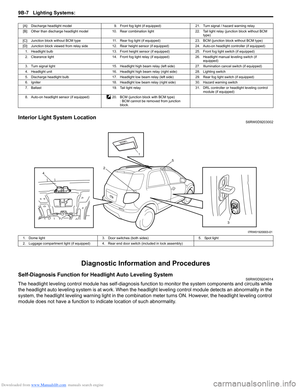
Interior Light System LocationS6RW0D9203002
Diagnostic Information and Procedures
Self-Diagnosis Function for Headlight Auto Leveling SystemS6RW0D9204014
The headlight leveling control module has self-diagnosis function to monitor the system components and circuits while
the headlight auto leveling system is at work. When the headlight leveling control module detects an abnormality in the
system, the headlight leveling warning light in the combination meter turns ON. However, the headlight leveling control
module does not have a function to indicate location of such abnormality.
[A]: Discharge headlight model 9. Front fog light (if equipped) 21. Turn signal / hazard warning relay
[B]: Other than discharge headlight model 10. Rear combination light 22. Tail light relay (junction block without BCM
type)
[C]: Junction block without BCM type 11. Rear fog light (if equipped) 23. BCM (junction block without BCM type)
[D]: Junction block viewed from relay side 12. Rear height sensor (if equipped) 24. Auto-on headlight controller (if equipped)
1. Headlight bulb 13. Front height sensor (if equipped) 25. Front fog light switch (if equipped)
2. Clearance light 14. Front fog light relay (if equipped) 26. Headlight manual leveling switch (if
equipped)
3. Turn signal light 15. Headlight high beam relay (left side) 27. Illumination cancel switch (if equipped)
4. Headlight unit 16. Headlight high beam relay (right side) 28. Lighting switch
5. Discharge headlight bulb 17. Headlight low beam relay (left side) 29. Rear fog light switch (if equipped)
6. Igniter 18. Headlight low beam relay (right side) 30. Hazard warning switch
7. Ballast 19. Tail light relay 31. DRL controller or headlight leveling control
module (if equipped)
8. Auto-on headlight sensor (if equipped) 20. BCM (junction block with BCM type)
: BCM cannot be removed from junction
block.
3 4
5
2
1
I7RW01920003-01
1. Dome light 3. Door switches (both sides) 5. Spot light
2. Luggage compartment light (if equipped) 4. Rear end door switch (included in lock assembly)
Page 1336 of 1556

Downloaded from www.Manualslib.com manuals search engine 9B-17 Lighting Systems:
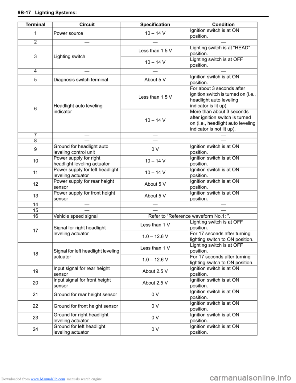
Terminal Circuit Specification Condition
1 Power source 10 – 14 VIgnition switch is at ON
position.
2———
3 Lighting switchLess than 1.5 VLighting switch is at “HEAD”
position.
10 – 14 VLighting switch is at OFF
position.
4———
5 Diagnosis switch terminal About 5 VIgnition switch is at ON
position.
6Headlight auto leveling
indicatorLess than 1.5 VFor about 3 seconds after
ignition switch is turned on (i.e.,
headlight auto leveling
indicator is lit up).
10 – 14 VMore than about 3 seconds
after ignition switch is turned
on (i.e., headlight auto leveling
indicator is not lit up).
7———
8———
9Ground for headlight auto
leveling control unit0 VIgnition switch is at ON
position.
10Power supply for right
headlight leveling actuator10 – 14 VIgnition switch is at ON
position.
11Power supply for left headlight
leveling actuator10 – 14 VIgnition switch is at ON
position.
12Power supply for rear height
sensorAbout 5 VIgnition switch is at ON
position.
13Power supply for front height
sensorAbout 5 VIgnition switch is at ON
position.
14———
15———
16 Vehicle speed signal Refer to “Reference waveform No.1: ”.
17Signal for right headlight
leveling actuatorLess than 1 VLighting switch is at OFF
position.
1.0 – 12.6 VFor 17 seconds after turning
lighting switch to ON position.
18Signal for left headlight leveling
actuatorLess than 1 VLighting switch is at OFF
position.
1.0 – 12.6 VFor 17 seconds after turning
lighting switch to ON position.
19Input signal for rear height
sensorAbout 2.5 VIgnition switch is at ON
position.
20Input signal for front height
sensorAbout 2.5 VIgnition switch is at ON
position.
21 Ground for rear height sensor 0 VIgnition switch is at ON
position.
22 Ground for front height sensor 0 VIgnition switch is at ON
position.
23Ground for right headlight
leveling actuator0 VIgnition switch is at ON
position.
24
Ground for left headlight
leveling actuator0 VIgnition switch is at ON
position.
Page 1478 of 1556

Downloaded from www.Manualslib.com manuals search engine 10B-5 Body Electrical Control System:
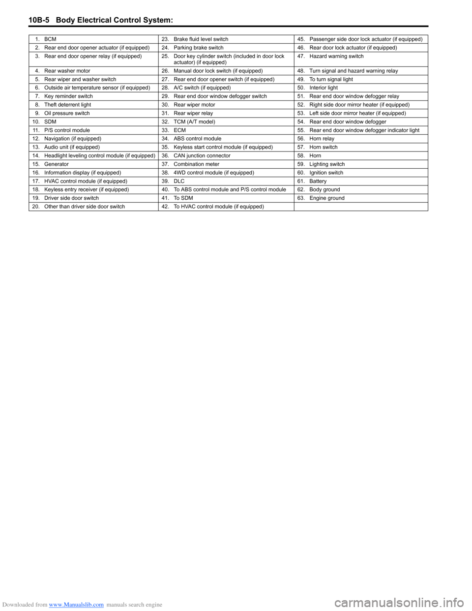
1. BCM 23. Brake fluid level switch 45. Passenger side door lock actuator (if equipped)
2. Rear end door opener actuator (if equipped) 24. Parking brake switch 46. Rear door lock actuator (if equipped)
3. Rear end door opener relay (if equipped) 25. Door key cylinder switch (included in door lock
actuator) (if equipped)47. Hazard warning switch
4. Rear washer motor 26. Manual door lock switch (if equipped) 48. Turn signal and hazard warning relay
5. Rear wiper and washer switch 27. Rear end door opener switch (if equipped) 49. To turn signal light
6. Outside air temperature sensor (if equipped) 28. A/C switch (if equipped) 50. Interior light
7. Key reminder switch 29. Rear end door window defogger switch 51. Rear end door window defogger relay
8. Theft deterrent light 30. Rear wiper motor 52. Right side door mirror heater (if equipped)
9. Oil pressure switch 31. Rear wiper relay 53. Left side door mirror heater (if equipped)
10. SDM 32. TCM (A/T model) 54. Rear end door window defogger
11. P/S control module 33. ECM 55. Rear end door window defogger indicator light
12. Navigation (if equipped) 34. ABS control module 56. Horn relay
13. Audio unit (if equipped) 35. Keyless start control module (if equipped) 57. Horn switch
14. Headlight leveling control module (if equipped) 36. CAN junction connector 58. Horn
15. Generator 37. Combination meter 59. Lighting switch
16. Information display (if equipped) 38. 4WD control module (if equipped) 60. Ignition switch
17. HVAC control module (if equipped) 39. DLC 61. Battery
18. Keyless entry receiver (if equipped) 40. To ABS control module and P/S control module 62. Body ground
19. Driver side door switch 41. To SDM 63. Engine ground
20. Other than driver side door switch 42. To HVAC control module (if equipped)