Page 394 of 1556

Downloaded from www.Manualslib.com manuals search engine 1G-17 Fuel System:
Fuel Pump InspectionS6RW0D1706016
• Check fuel pump assembly for damage.
• Check fuel suction filter for evidence of dirt and
contamination.
If present, replace or clean and check for presence of
dirt in fuel tank.
• For electrical circuit, refer to “Fuel Pump and Its
Circuit Check in Section 1A”.
• For inspection of fuel level gauge (1), refer to “Fuel
Level Sensor Inspection in Section 9C”.
Specifications
Tightening Torque SpecificationsS6RW0D1707001
NOTE
The specified tightening torque is also described in the following.
“Fuel System Components”
“Fuel Hose Disconnecting and Reconnecting”
Reference:
For the tightening torque of fastener not specified in this section, refer to “Fasteners Information in Section 0A”.
1
I5JB0A171027-01
Fastening partTightening torque
Note
N⋅mkgf-mlb-ft
Fuel delivery pipe bolt 25 2.5 18.0�)
Ground wire bolt 11 1.1 8.0�)
Fuel tank bolt 45 4.5 33.0�)
Fuel filler hose clamp 1.5 0.15 1.0�)
Fuel pump assembly bolt 11 1.1 8.0�)
Page 395 of 1556
Downloaded from www.Manualslib.com manuals search engine Fuel System: 1G-18
Special Tools and Equipment
Special ToolS6RW0D1708001
09912–57610 09912–58421
Injector checking tool plate Checking tool set
�)This kit includes the
following items. 1. Tool body
and washer, 2. Body plug, 3.
Body attachment-1, 4.
Holder, 5. Return hose and
clamp, 6. Body attachment-2
and washer, 7. Hose
attachment-1, 8. Hose
attachment-2 �)
09912–58432 09912–58442
Fuel pressure gauge hose Fuel pressure gauge
This tool is included in fuel
pressure gauge set (09912-
58413). �)This tool is included in fuel
pressure gauge set (09912-
58413). �)
09912–58490 09919–47020
3-way joint & hose Quick joint remover
�)�)
09930–88530 SUZUKI scan tool (SUZUKI-
SDT)
Injector test lead —
�)This kit includes following
items. 1. SUZUKI-SDT 2.
DLC3 cable 3. USB cable 4.
AC/DC power supply 5.
Voltage meter probe 6.
Storage case �)
1
2
34
56
Page 1196 of 1556
Downloaded from www.Manualslib.com manuals search engine 9A-29 Wiring Systems:
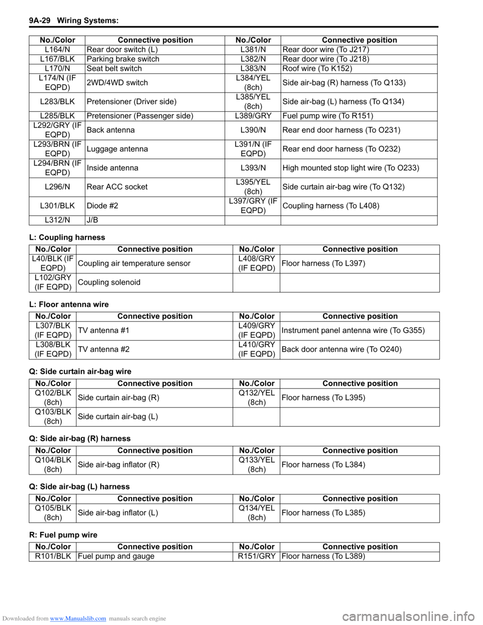
L: Coupling harness
L: Floor antenna wire
Q: Side curtain air-bag wire
Q: Side air-bag (R) harness
Q: Side air-bag (L) harness
R: Fuel pump wireL164/N Rear door switch (L) L381/N Rear door wire (To J217)
L167/BLK Parking brake switch L382/N Rear door wire (To J218)
L170/N Seat belt switch L383/N Roof wire (To K152)
L174/N (IF
EQPD)2WD/4WD switchL384/YEL
(8ch)Side air-bag (R) harness (To Q133)
L283/BLK Pretensioner (Driver side)L385/YEL
(8ch)Side air-bag (L) harness (To Q134)
L285/BLK Pretensioner (Passenger side) L389/GRY Fuel pump wire (To R151)
L292/GRY (IF
EQPD)Back antenna L390/N Rear end door harness (To O231)
L293/BRN (IF
EQPD)Luggage antennaL391/N (IF
EQPD)Rear end door harness (To O232)
L294/BRN (IF
EQPD)Inside antenna L393/N High mounted stop light wire (To O233)
L296/N Rear ACC socketL395/YEL
(8ch)Side curtain air-bag wire (To Q132)
L301/BLK Diode #2L397/GRY (IF
EQPD)Coupling harness (To L408)
L312/N J/B No./Color Connective position No./Color Connective position
No./Color Connective position No./Color Connective position
L40/BLK (IF
EQPD)Coupling air temperature sensorL408/GRY
(IF EQPD)Floor harness (To L397)
L102/GRY
(IF EQPD)Coupling solenoid
No./Color Connective position No./Color Connective position
L307/BLK
(IF EQPD)TV antenna #1L409/GRY
(IF EQPD)Instrument panel antenna wire (To G355)
L308/BLK
(IF EQPD)TV antenna #2L410/GRY
(IF EQPD)Back door antenna wire (To O240)
No./Color Connective position No./Color Connective position
Q102/BLK
(8ch)Side curtain air-bag (R)Q132/YEL
(8ch)Floor harness (To L395)
Q103/BLK
(8ch)Side curtain air-bag (L)
No./Color Connective position No./Color Connective position
Q104/BLK
(8ch)Side air-bag inflator (R)Q133/YEL
(8ch)Floor harness (To L384)
No./Color Connective position No./Color Connective position
Q105/BLK
(8ch)Side air-bag inflator (L)Q134/YEL
(8ch)Floor harness (To L385)
No./Color Connective position No./Color Connective position
R101/BLK Fuel pump and gauge R151/GRY Floor harness (To L389)
Page 1198 of 1556
Downloaded from www.Manualslib.com manuals search engine 9A-31 Wiring Systems:
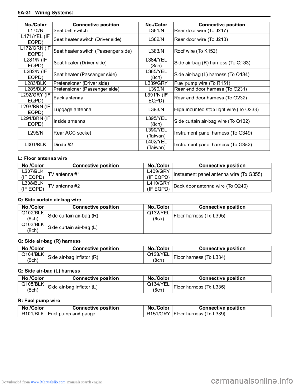
L: Floor antenna wire
Q: Side curtain air-bag wire
Q: Side air-bag (R) harness
Q: Side air-bag (L) harness
R: Fuel pump wireL170/N Seat belt switch L381/N Rear door wire (To J217)
L171/YEL (IF
EQPD)Seat heater switch (Driver side) L382/N Rear door wire (To J218)
L172/GRN (IF
EQPD)Seat heater switch (Passenger side) L383/N Roof wire (To K152)
L281/N (IF
EQPD)Seat heater (Driver side)L384/YEL
(8ch)Side air-bag (R) harness (To Q133)
L282/N (IF
EQPD)Seat heater (Passenger side)L385/YEL
(8ch)Side air-bag (L) harness (To Q134)
L283/BLK Pretensioner (Driver side) L389/GRY Fuel pump wire (To R151)
L285/BLK Pretensioner (Passenger side) L390/N Rear end door harness (To O231)
L292/GRY (IF
EQPD)Back antennaL391/N (IF
EQPD)Rear end door harness (To O232)
L293/BRN (IF
EQPD)Luggage antenna L393/N High mounted stop light wire (To O233)
L294/BRN (IF
EQPD)Inside antennaL395/YEL
(8ch)Side curtain air-bag wire (To Q132)
L296/N Rear ACC socketL399/YEL
(Taiwan)Instrument panel harness (To G349)
L301/BLK Diode #2L402/YEL
(Taiwan)Instrument panel harness (To G352) No./Color Connective position No./Color Connective position
No./Color Connective position No./Color Connective position
L307/BLK
(IF EQPD)TV antenna #1L409/GRY
(IF EQPD)Instrument panel antenna wire (To G355)
L308/BLK
(IF EQPD)TV antenna #2L410/GRY
(IF EQPD)Back door antenna wire (To O240)
No./Color Connective position No./Color Connective position
Q102/BLK
(8ch)Side curtain air-bag (R)Q132/YEL
(8ch)Floor harness (To L395)
Q103/BLK
(8ch)Side curtain air-bag (L)
No./Color Connective position No./Color Connective position
Q104/BLK
(8ch)Side air-bag inflator (R)Q133/YEL
(8ch)Floor harness (To L384)
No./Color Connective position No./Color Connective position
Q105/BLK
(8ch)Side air-bag inflator (L)Q134/YEL
(8ch)Floor harness (To L385)
No./Color Connective position No./Color Connective position
R101/BLK Fuel pump and gauge R151/GRY Floor harness (To L389)
Page 1231 of 1556
Downloaded from www.Manualslib.com manuals search engine Wiring Systems: 9A-64
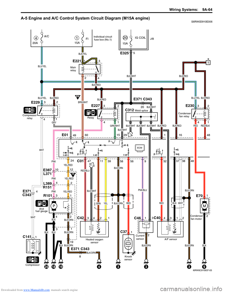
A-5 Engine and A/C Control System Circuit Diagram (M15A engine)S6RW0D910E006
YEL/RED
E387
L3711012
L389
R15142
PNKYEL/RED
P
PNKYEL/RED
31
433
31
E371 C343
BLK/ORN
BLK/ORN
BLK/ORN
BLK/ORN
19
8
BLK42
R101
1
And
fuel gauge
Main
relay
1
BLK/WHT
BLK/REDBLU/YEL
C312Weld splice
GRN/WHTBLK/WHT
BLK/WHT
BLK/WHT
IG COILJ/B1
15A
FI
BLK/YEL
E2211
23
415A
20
BRN/WHT
BW
YR
4
20A
A/C
Compressor
relay
E229
Relay
BLU/YEL
BLU/YEL
Compressor
C1411
E3255
E371 C343
20
E371
C3434BLK/WHT
C42C40
Heated oxygen
sensor
RED/BLU
BRN
A/F sensorCondenser
fan motor Condenser
fan relay
BLK
BLK/ORN
BLK/ORN
RED
C01
1
34 2 143 12
4711393237
WHT
3848PNK
ECM
142
3
WHT
WHT
BLK/RED
BLK/REDBLK/WHT
BLK/RED
BLK/RED
BLK/RED
E01496015291
GRY
E22732
4
1
E23032
4
1
YELBLK/ORN
24
BLKBLK
58 56
BLK/REDRED
16 48
182419
Individual circuit
fuse box (No.1)
BLKBLKBLK/ORNBLK/ORN
93
RED/BLK
M
1
2E70
9
PNK/BLU
RED
Knock
sensor
C371
BLK/WHT
Current
sensor
C461
23
I6RW0C910937-03
Page 1235 of 1556
Downloaded from www.Manualslib.com manuals search engine Wiring Systems: 9A-68
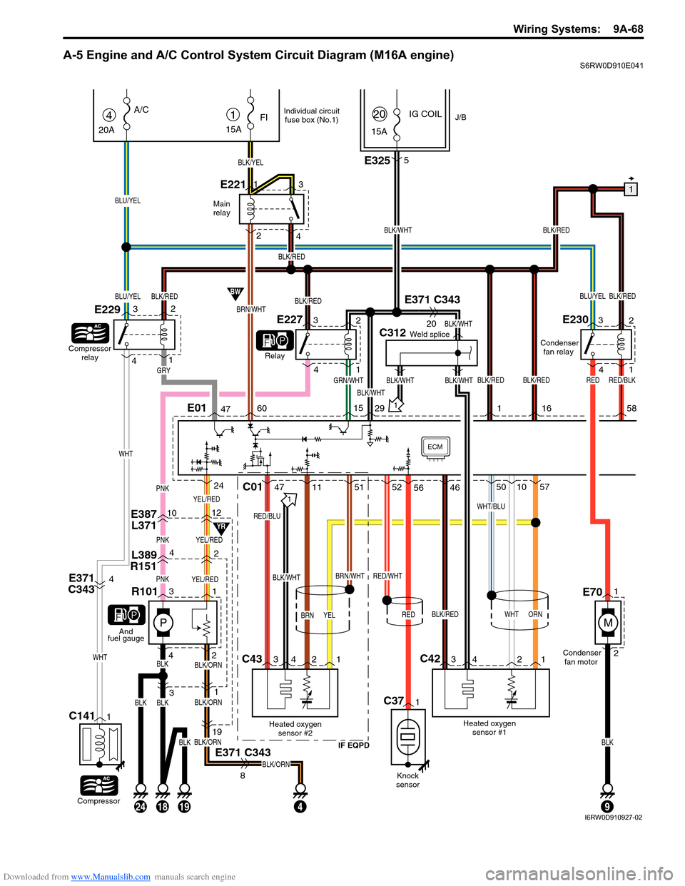
A-5 Engine and A/C Control System Circuit Diagram (M16A engine)S6RW0D910E041
YEL/RED
E387
L3711012
L389
R15142
PNKYEL/RED
P
PNKYEL/RED
31
4
31
E371 C343
BLK/ORN
BLK/ORN
BLK/ORN
BLK/ORN
19
8
BLK42
R101
1
And
fuel gauge
Main
relay
1
BLK/WHT
BLK/REDBLU/YEL
C312Weld splice
GRN/WHTBLK/WHT
BLK/WHT
BLK/WHT
IG COILJ/B1
15A
FI
BLK/YEL
E2211
23
415A
20
BRN/WHT
BW
YR
4
20A
A/C
Compressor
relay
E229
Relay
BLU/YEL
BLU/YEL
Compressor
C1411
E3255
E371 C343
20
E371
C3434BLK/WHT
C43C42
Heated oxygen
sensor #2
IF EQPD
RED/BLU
BRN
Heated oxygen
sensor #1Condenser
fan motor Condenser
fan relay
WHT
BRN/WHT
BLK/RED
WHT/BLU
C01
1
34 2 134 2 1
471151
RED/WHT
52461050
ORN
57PNK
ECM
142
3
WHT
WHT
BLK/RED
BLK/REDBLK/WHT
BLK/RED
BLK/RED
BLK/RED
E01476015291
GRY
E22732
4
1
E23032
4
1
YEL
24
BLKBLK
56
BLK/REDRED
16 58
182419
Individual circuit
fuse box (No.1)
BLKBLK
9
RED/BLK
M
1
2E70
RED
Knock
sensor
C371
I6RW0D910927-02
Page 1239 of 1556
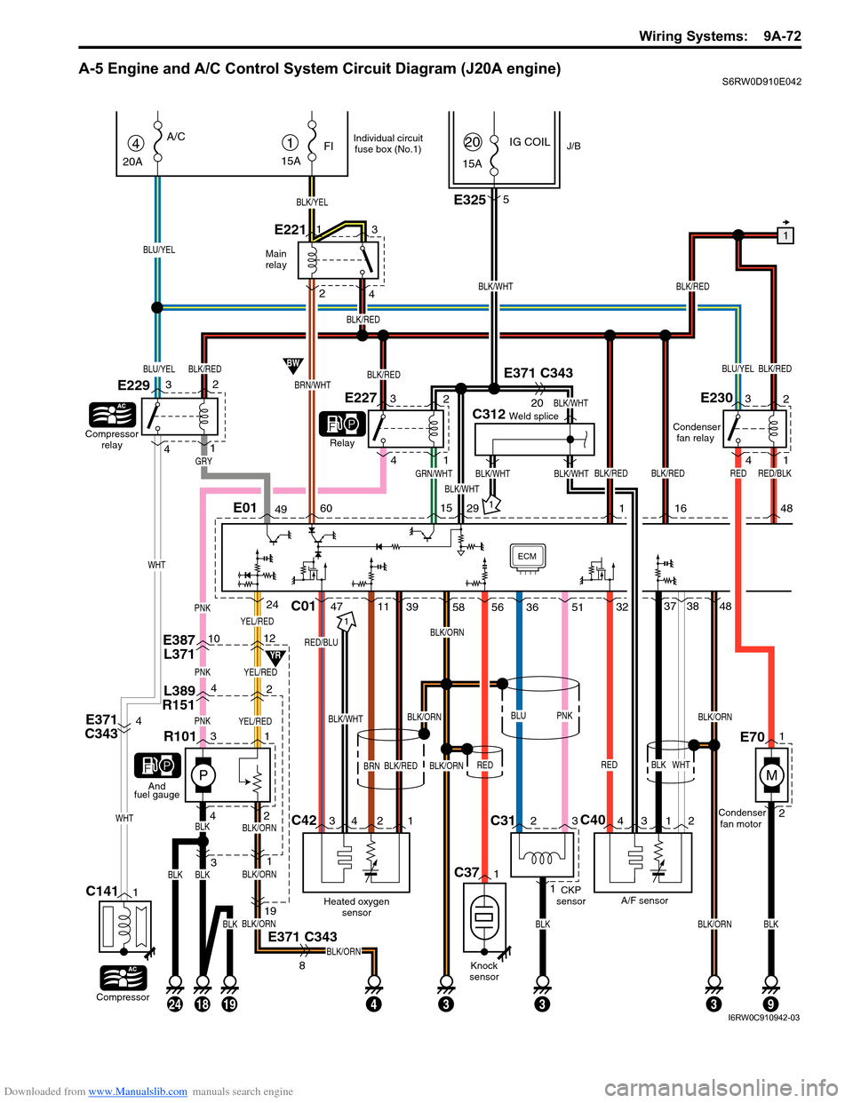
Downloaded from www.Manualslib.com manuals search engine Wiring Systems: 9A-72
A-5 Engine and A/C Control System Circuit Diagram (J20A engine)S6RW0D910E042
YEL/RED
E387
L3711012
L389
R15142
PNKYEL/RED
P
PNKYEL/RED
31
433
31
E371 C343
BLK/ORN
BLK/ORN
BLK/ORN
BLK/ORN
19
8
BLK42
R101
1
And
fuel gauge
Main
relay
1
BLK/WHT
BLK/REDBLU/YEL
C312Weld splice
GRN/WHTBLK/WHT
BLK/WHT
BLK/WHT
IG COILJ/B1
15A
FI
BLK/YEL
E2211
23
415A
20
BRN/WHT
BW
YR
4
20A
A/C
Compressor
relay
E229
Relay
BLU/YEL
BLU/YEL
Compressor
C1411
C312
13
E3255
E371 C343
20
E371
C3434BLK/WHT
C42C40
Heated oxygen
sensor
RED/BLU
BRN
A/F sensor CKP
sensorCondenser
fan motor Condenser
fan relay
BLK
BLK/ORNBLK/ORN
BLK/ORN
RED
C01
1
34 2 143 12
4711393237
WHT
3848PNK
ECM
142
3
WHT
WHT
BLK/RED
BLK/REDBLK/WHT
BLK/RED
BLK/RED
BLK/RED
E01496015291
GRY
E22732
4
1
E23032
4
1
BLK/REDBLK/ORN
24
BLKBLK
58 56
BLK/REDRED
16 48
182419
Individual circuit
fuse box (No.1)
BLKBLKBLK/ORNBLK
93
RED/BLK
M
1
2E70
3651
BLUPNK
RED
Knock
sensor
C371
I6RW0C910942-03