2006 SUZUKI SX4 Defogger
[x] Cancel search: DefoggerPage 984 of 1556

Downloaded from www.Manualslib.com manuals search engine 7B-44 Air Conditioning System: Automatic Type
Electronic Control System Components LocationS6RW0D7223002
NOTE
The figure shows left-hand steering vehicle. For right-hand steering vehicle, parts with (*) are installed
at the opposite side.
[A]
2
3
5
1
4
78*
18
19
20
23
22 219*
10*
11*
12*
13*
15* 16* 17
14*
8*6
I6RW0C722003-01
[A]: Junction block assembly viewed from relay
side8. Junction block assembly 16. Blower motor controller
1. A/C refrigerant pressure sensor 9. Sunload sensor 17. HVAC control module
2. Compressor relay 10. Inside air temperature sensor 18. Temperature selector
3. Condenser cooling fan relay 11. Air flow control actuator 19. Blower speed selector
4. Outside air temperature sensor 12. Temperature control actuator 20. MODE (air flow) selector
5. ECT sensor 13. Evaporator temperature sensor 21. A/C switch
6. Condenser cooling fan 14. Air intake actuator 22. Air intake selector
7. Blower motor relay 15. Blower motor 23. Rear defogger switch
Page 1016 of 1556
Downloaded from www.Manualslib.com manuals search engine 7B-76 Air Conditioning System: Automatic Type
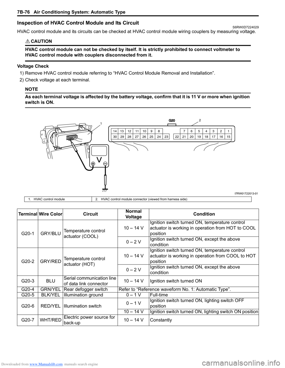
Inspection of HVAC Control Module and Its CircuitS6RW0D7224029
HVAC control module and its circuits can be checked at HVAC control module wiring couplers by measuring voltage.
CAUTION!
HVAC control module can not be checked by itself. It is strictly prohibited to connect voltmeter to
HVAC control module with couplers disconnected from it.
Voltage Check
1) Remove HVAC control module referring to “HVAC Control Module Removal and Installation”.
2) Check voltage at each terminal.
NOTE
As each terminal voltage is affected by the battery voltage, confirm that it is 11 V or more when ignition
switch is ON.
G20
1 2 3 4 5 6 7 8 9 10 11 12 13 14
15 16 17 18 19 20 21 24 23 22 25 26 27 28 29 30
12
I7RW01722013-01
1. HVAC control module 2. HVAC control module connector (viewed from harness side)
Terminal Wire Color CircuitNormal
Vo l ta g eCondition
G20-1 GRY/BLUTemperature control
actuator (COOL)10 – 14 VIgnition switch turned ON, temperature control
actuator is working in operation from HOT to COOL
position
0 – 2 VIgnition switch turned ON, except the above
condition
G20-2 GRY/REDTemperature control
actuator (HOT)10 – 14 VIgnition switch turned ON, temperature control
actuator is working in operation from COOL to HOT
position
0 – 2 VIgnition switch turned ON, except the above
condition
G20-3 BLUSerial communication line
of data link connector10 – 14 V Ignition switch turned ON
G20-4 GRN/YEL Rear defogger switchRefer to “Reference waveform No. 1: Automatic Type”.
G20-5 BLK/YEL Illumination ground 0 – 1 V Full-time
G20-6 RED/YEL Illumination switch0 – 1 VIgnition switch turned ON, lighting switch OFF
position
10 – 14 V Ignition switch turned ON, lighting switch ON position
G20-7 WHT/REDElectric power source for
back-up10 – 14 V Constantly
Page 1018 of 1556
Downloaded from www.Manualslib.com manuals search engine 7B-78 Air Conditioning System: Automatic Type
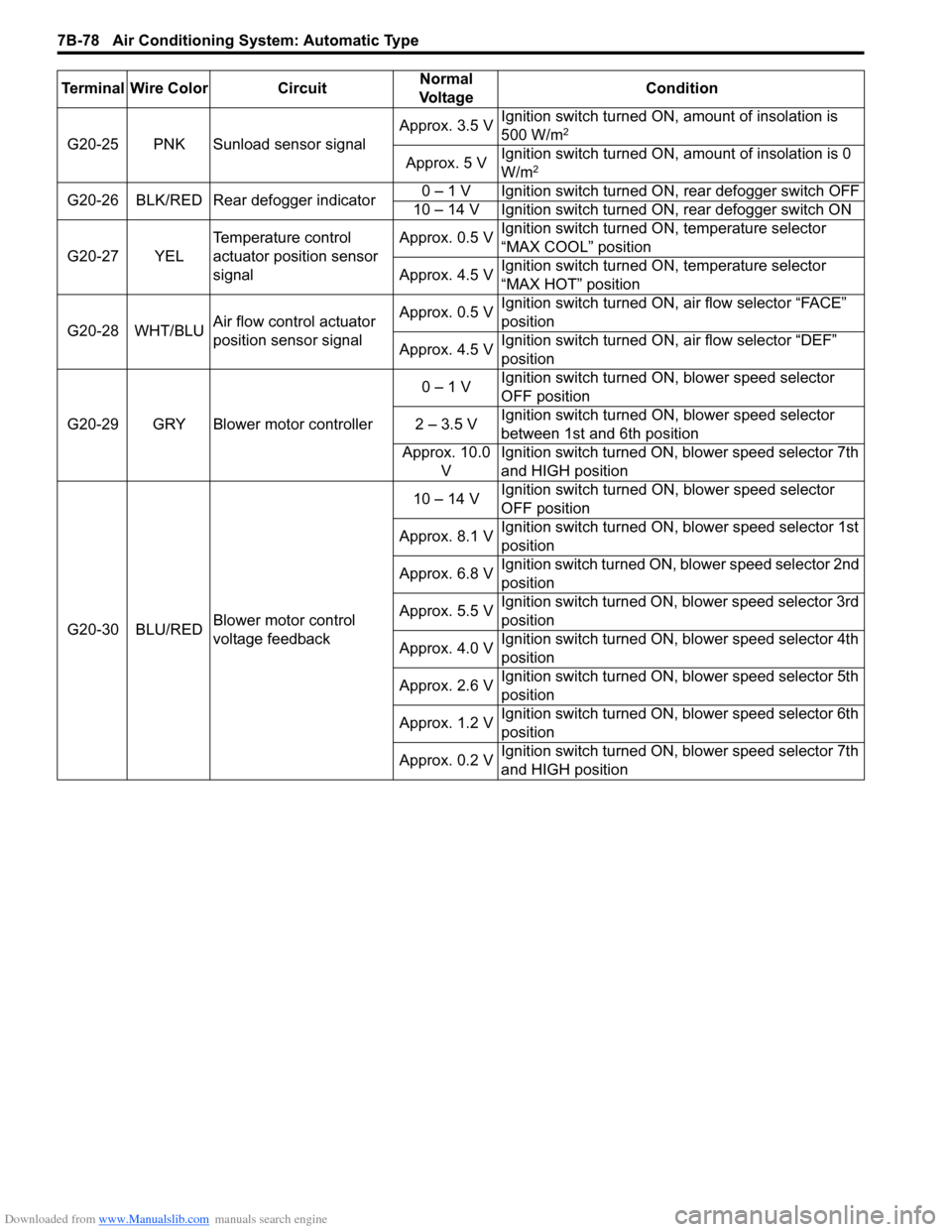
G20-25 PNK Sunload sensor signalApprox. 3.5 VIgnition switch turned ON, amount of insolation is
500 W/m2
Approx. 5 VIgnition switch turned ON, amount of insolation is 0
W/m2
G20-26 BLK/RED Rear defogger indicator0 – 1 V Ignition switch turned ON, rear defogger switch OFF
10 – 14 V Ignition switch turned ON, rear defogger switch ON
G20-27 YELTemperature control
actuator position sensor
signalApprox. 0.5 VIgnition switch turned ON, temperature selector
“MAX COOL” position
Approx. 4.5 VIgnition switch turned ON, temperature selector
“MAX HOT” position
G20-28 WHT/BLUAir flow control actuator
position sensor signalApprox. 0.5 VIgnition switch turned ON, air flow selector “FACE”
position
Approx. 4.5 VIgnition switch turned ON, air flow selector “DEF”
position
G20-29 GRY Blower motor controller0 – 1 VIgnition switch turned ON, blower speed selector
OFF position
2 – 3.5 VIgnition switch turned ON, blower speed selector
between 1st and 6th position
Approx. 10.0
VIgnition switch turned ON, blower speed selector 7th
and HIGH position
G20-30 BLU/REDBlower motor control
voltage feedback10 – 14 VIgnition switch turned ON, blower speed selector
OFF position
Approx. 8.1 VIgnition switch turned ON, blower speed selector 1st
position
Approx. 6.8 VIgnition switch turned ON, blower speed selector 2nd
position
Approx. 5.5 VIgnition switch turned ON, blower speed selector 3rd
position
Approx. 4.0 VIgnition switch turned ON, blower speed selector 4th
position
Approx. 2.6 VIgnition switch turned ON, blower speed selector 5th
position
Approx. 1.2 VIgnition switch turned ON, blower speed selector 6th
position
Approx. 0.2 VIgnition switch turned ON, blower speed selector 7th
and HIGH position Terminal Wire Color CircuitNormal
Vo l ta g eCondition
Page 1019 of 1556
Downloaded from www.Manualslib.com manuals search engine Air Conditioning System: Automatic Type 7B-79
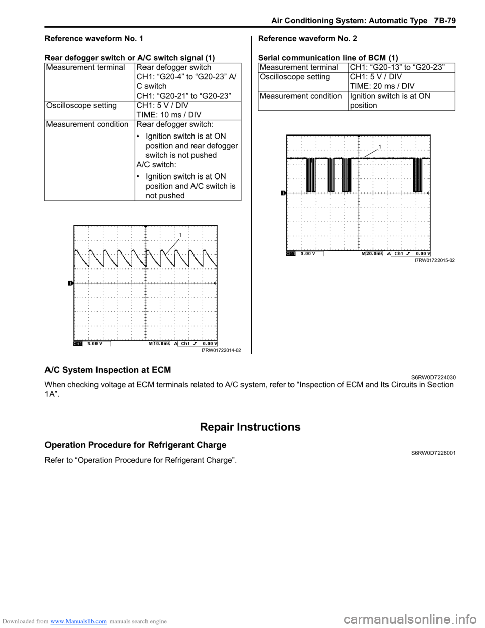
Reference waveform No. 1
Rear defogger switch or A/C switch signal (1)Reference waveform No. 2
Serial communication line of BCM (1)
A/C System Inspection at ECMS6RW0D7224030
When checking voltage at ECM terminals related to A/C system, refer to “Inspection of ECM and Its Circuits in Section
1A”.
Repair Instructions
Operation Procedure for Refrigerant ChargeS6RW0D7226001
Refer to “Operation Procedure for Refrigerant Charge”.Measurement terminal Rear defogger switch
CH1: “G20-4” to “G20-23” A/
C switch
CH1: “G20-21” to “G20-23”
Oscilloscope setting CH1: 5 V / DIV
TIME: 10 ms / DIV
Measurement condition Rear defogger switch:
• Ignition switch is at ON
position and rear defogger
switch is not pushed
A/C switch:
• Ignition switch is at ON
position and A/C switch is
not pushed
I7RW01722014-02
Measurement terminal CH1: “G20-13” to “G20-23”
Oscilloscope setting CH1: 5 V / DIV
TIME: 20 ms / DIV
Measurement condition Ignition switch is at ON
position
I7RW01722015-02
Page 1161 of 1556
Downloaded from www.Manualslib.com manuals search engine Table of Contents 9- i
9
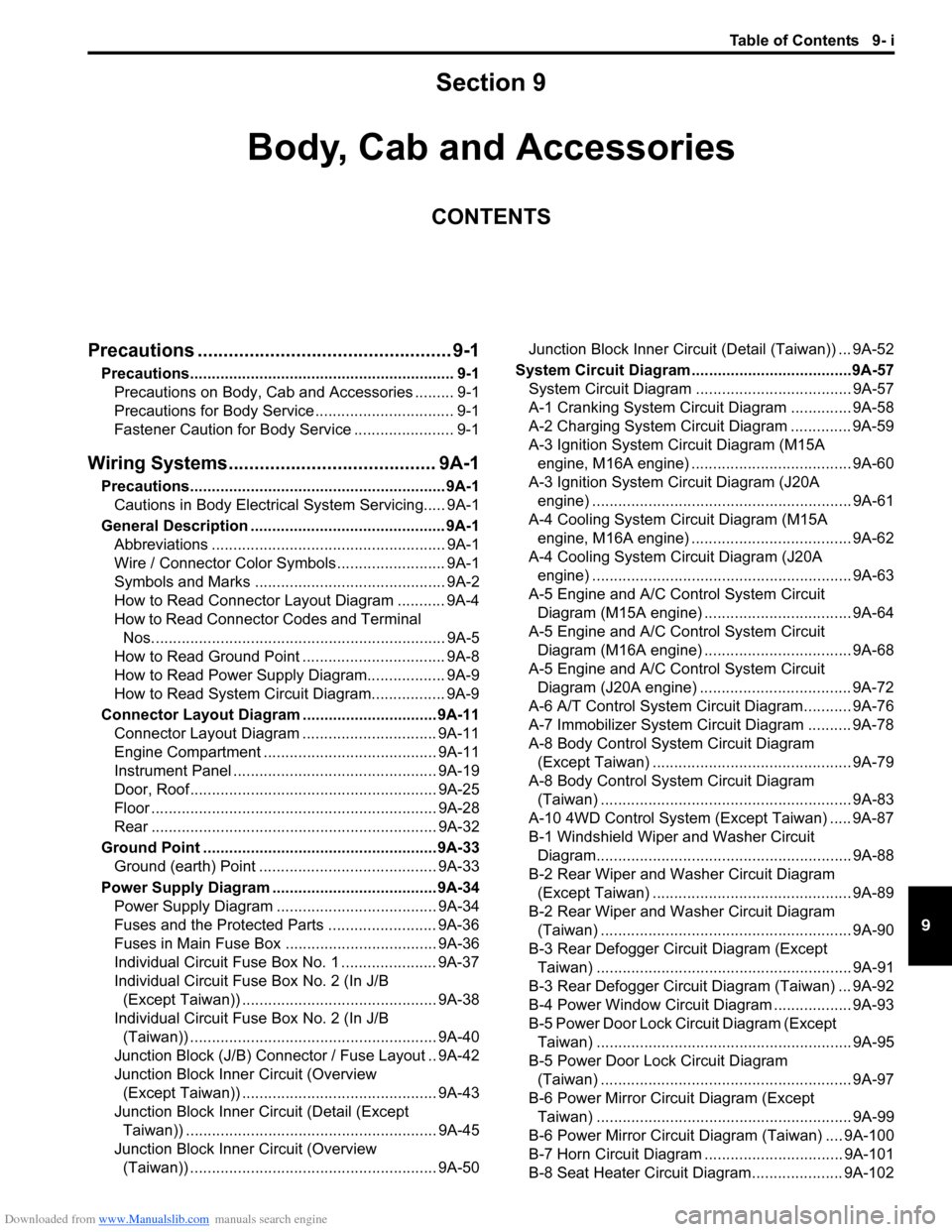
Section 9
CONTENTS
Body, Cab and Accessories
Precautions ................................................. 9-1
Precautions............................................................. 9-1
Precautions on Body, Cab and Accessories ......... 9-1
Precautions for Body Service ................................ 9-1
Fastener Caution for Body Service ....................... 9-1
Wiring Systems........................................ 9A-1
Precautions........................................................... 9A-1
Cautions in Body Electrical System Servicing..... 9A-1
General Description ............................................. 9A-1
Abbreviations ...................................................... 9A-1
Wire / Connector Color Symbols ......................... 9A-1
Symbols and Marks ............................................ 9A-2
How to Read Connector Layout Diagram ........... 9A-4
How to Read Connector Codes and Terminal
Nos.................................................................... 9A-5
How to Read Ground Point ................................. 9A-8
How to Read Power Supply Diagram.................. 9A-9
How to Read System Circuit Diagram................. 9A-9
Connector Layout Diagram ............................... 9A-11
Connector Layout Diagram ............................... 9A-11
Engine Compartment ........................................ 9A-11
Instrument Panel ............................................... 9A-19
Door, Roof......................................................... 9A-25
Floor .................................................................. 9A-28
Rear .................................................................. 9A-32
Ground Point ...................................................... 9A-33
Ground (earth) Point ......................................... 9A-33
Power Supply Diagram ...................................... 9A-34
Power Supply Diagram ..................................... 9A-34
Fuses and the Protected Parts ......................... 9A-36
Fuses in Main Fuse Box ................................... 9A-36
Individual Circuit Fuse Box No. 1 ...................... 9A-37
Individual Circuit Fuse Box No. 2 (In J/B
(Except Taiwan)) ............................................. 9A-38
Individual Circuit Fuse Box No. 2 (In J/B
(Taiwan)) ......................................................... 9A-40
Junction Block (J/B) Connector / Fuse Layout .. 9A-42
Junction Block Inner Circuit (Overview
(Except Taiwan)) ............................................. 9A-43
Junction Block Inner Circuit (Detail (Except
Taiwan)) .......................................................... 9A-45
Junction Block Inner Circuit (Overview
(Taiwan)) ......................................................... 9A-50Junction Block Inner Circuit (Detail (Taiwan)) ... 9A-52
System Circuit Diagram.....................................9A-57
System Circuit Diagram .................................... 9A-57
A-1 Cranking System Circuit Diagram .............. 9A-58
A-2 Charging System Circuit Diagram .............. 9A-59
A-3 Ignition System Circuit Diagram (M15A
engine, M16A engine) ..................................... 9A-60
A-3 Ignition System Circuit Diagram (J20A
engine) ............................................................ 9A-61
A-4 Cooling System Circuit Diagram (M15A
engine, M16A engine) ..................................... 9A-62
A-4 Cooling System Circuit Diagram (J20A
engine) ............................................................ 9A-63
A-5 Engine and A/C Control System Circuit
Diagram (M15A engine) .................................. 9A-64
A-5 Engine and A/C Control System Circuit
Diagram (M16A engine) .................................. 9A-68
A-5 Engine and A/C Control System Circuit
Diagram (J20A engine) ................................... 9A-72
A-6 A/T Control System Circuit Diagram........... 9A-76
A-7 Immobilizer System Circuit Diagram .......... 9A-78
A-8 Body Control System Circuit Diagram
(Except Taiwan) .............................................. 9A-79
A-8 Body Control System Circuit Diagram
(Taiwan) .......................................................... 9A-83
A-10 4WD Control System (Except Taiwan) ..... 9A-87
B-1 Windshield Wiper and Washer Circuit
Diagram........................................................... 9A-88
B-2 Rear Wiper and Washer Circuit Diagram
(Except Taiwan) .............................................. 9A-89
B-2 Rear Wiper and Washer Circuit Diagram
(Taiwan) .......................................................... 9A-90
B-3 Rear Defogger Circuit Diagram (Except
Taiwan) ........................................................... 9A-91
B-3 Rear Defogger Circuit Diagram (Taiwan) ... 9A-92
B-4 Power Window Circuit Diagram .................. 9A-93
B-5 Power Door Lock Circuit Diagram (Except
Taiwan) ........................................................... 9A-95
B-5 Power Door Lock Circuit Diagram
(Taiwan) .......................................................... 9A-97
B-6 Power Mirror Circuit Diagram (Except
Taiwan) ........................................................... 9A-99
B-6 Power Mirror Circuit Diagram (Taiwan) .... 9A-100
B-7 Horn Circuit Diagram ................................ 9A-101
B-8 Seat Heater Circuit Diagram..................... 9A-102
Page 1164 of 1556
Downloaded from www.Manualslib.com manuals search engine 9-iv Table of Contents
Front Speaker Removal and Installation (If
Equipped) ........................................................9C-19
Rear Speaker Removal and Installation (If
Equipped) ........................................................9C-19
GPS Antenna Removal and Installation (If
Equipped) ........................................................9C-20
Horn Removal and Installation ..........................9C-20
Horn Inspection .................................................9C-20
Horn Relay Inspection .......................................9C-20
Antenna Base Removal and Installation ...........9C-21
Remote Audio Control Switch Removal and
Installation (If Equipped) .................................9C-21
Remote Audio Control Switch Inspection (If
Equipped) ........................................................9C-22
Vehicle Speed Signal Inspection (For Audio
Unit) (If Equipped) ...........................................9C-22
Specifications .....................................................9C-22
Tightening Torque Specifications ......................9C-22
Wipers / Washers .................................... 9D-1
Diagnostic Information and Procedures ............ 9D-1
Front Wiper and Washer Symptom Diagnosis ....9D-1
Rear Wiper and Washer Symptom Diagnosis..... 9D-1
Repair Instructions ..............................................9D-2
Wipers and Washers Components .....................9D-2
Washer Tank and Washer Pump Removal
and Installation ..................................................9D-3
Washer Pump Inspection ....................................9D-3
Windshield Wiper Removal and Installation ........9D-3
Windshield Wiper Motor Inspection.....................9D-4
Rear Wiper Removal and Installation.................. 9D-6
Rear Wiper Motor Inspection ..............................9D-7
Windshield Wiper and Washer Switch
Removal and Installation ................................... 9D-8
Windshield Wiper and Washer Switch
Inspection .......................................................... 9D-8
Rear Wiper and Washer Switch Removal and
Installation .......................................................9D-10
Rear Wiper and Washer Switch Inspection.......9D-10
Rear Wiper Relay Removal and Installation .....9D-10
Rear Wiper Relay Inspection ............................9D-10
Specifications .....................................................9D-11
Tightening Torque Specifications ......................9D-11
Glass / Windows / Mirrors .......................9E-1
Precautions........................................................... 9E-1
Precautions for Power Window Service
(Pinching Prevention Function Model) .............. 9E-1
General Description ............................................. 9E-1
Rear End Door Window Defogger System
Description ........................................................ 9E-1
Schematic and Routing Diagram ........................ 9E-2
Power Window Circuit Diagram (Pinching
Prevention Function Model) .............................. 9E-2
Diagnostic Information and Procedures ............ 9E-3
Rear End door Window Defogger Symptom
Diagnosis .......................................................... 9E-3
Power Window Control System Symptom
Diagnosis .......................................................... 9E-3Inspection of Pinching Prevention Function
(Pinching Prevention Function Model) .............. 9E-4
Power Door Mirror Control System Symptom
Diagnosis .......................................................... 9E-4
Door Mirror Heater Symptom Diagnosis (If
Equipped) .......................................................... 9E-5
Repair Instructions .............................................. 9E-5
Windshield Components ..................................... 9E-5
Windshield Removal and Installation .................. 9E-6
Front Pillar Window Components...................... 9E-10
Front Pillar Window Removal and Installation... 9E-10
Rear Quarter Window Components .................. 9E-11
Rear Quarter Window Removal and
Installation ....................................................... 9E-11
Rear End Door Window Components ............... 9E-12
Rear End Door Glass Removal and
Installation ....................................................... 9E-12
Front Door Window Components ...................... 9E-13
Front Door Glass Removal and Installation ...... 9E-14
Front Door Window Regulator Removal and
Installation ....................................................... 9E-15
Front Door Window Regulator Inspection ......... 9E-15
Rear Door Window Components ...................... 9E-16
Rear Door Glass Removal and Installation ....... 9E-16
Rear Door Window Regulator Removal and
Installation ....................................................... 9E-18
Rear Door Window Regulator Inspection .......... 9E-18
Rear End Door Window Defogger Switch
Inspection ........................................................ 9E-18
Rear End Door Window Defogger Relay
Inspection ........................................................ 9E-19
Rear End Door Window Defogger Wire
Inspection ........................................................ 9E-19
Rear End Door Window Defogger Wire
Repair.............................................................. 9E-20
Power Window Main Switch Inspection ............ 9E-20
Power Window Sub Switch Inspection .............. 9E-22
Pulse Sensor and Its Circuit Inspection
(Pinching Prevention Function Model) ............ 9E-23
Power Window Main Switch Initialization
(Pinching Prevention Function Model) ............ 9E-24
Door Mirror Components................................... 9E-24
Door Mirror Removal and Installation................ 9E-25
Power Door Mirror Switch Inspection ................ 9E-25
Power Door Mirror Actuator Inspection ............. 9E-25
Door Mirror Heater Inspection (If Equipped) ..... 9E-26
Door Mirror Heater Switch Inspection (If
Equipped) ........................................................ 9E-26
Special Tools and Equipment ........................... 9E-26
Recommended Service Material ....................... 9E-26
Security and Locks...................................9F-1
General Description ............................................. 9F-1
Key Coding Construction .................................... 9F-1
Rear End Door Opener System Description ....... 9F-1
Component Location ........................................... 9F-2
Power Door Lock and Keyless Entry System
Component Location (If Equipped) ................... 9F-2
Diagnostic Information and Procedures ............ 9F-3
Page 1170 of 1556
Downloaded from www.Manualslib.com manuals search engine 9A-3 Wiring Systems:
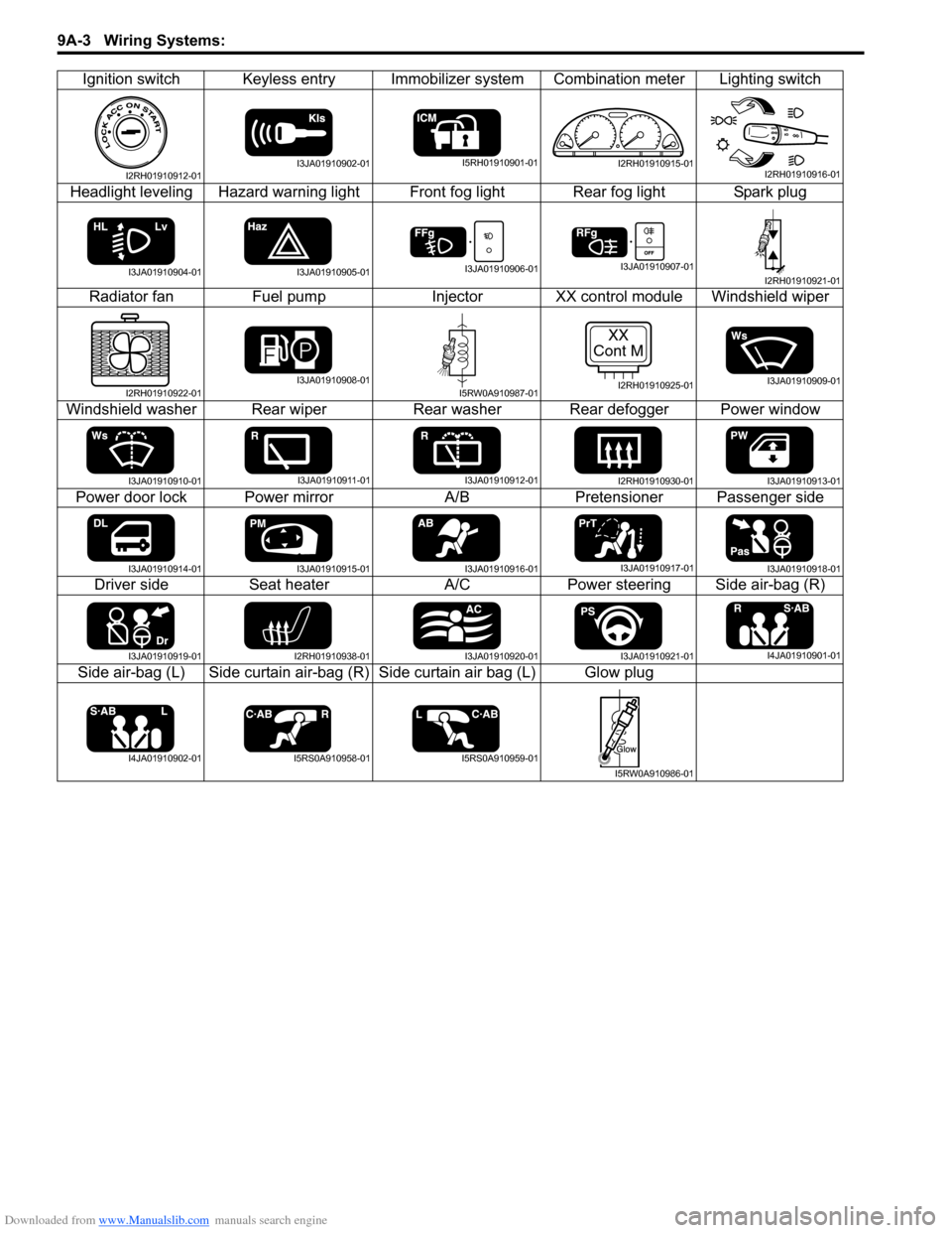
Ignition switch Keyless entry Immobilizer system Combination meter Lighting switch
Headlight leveling Hazard warning light Front fog light Rear fog light Spark plug
Radiator fan Fuel pump Injector XX control module Windshield wiper
Windshield washer Rear wiper Rear washer Rear defogger Power window
Power door lock Power mirror A/B Pretensioner Passenger side
Driver side Seat heater A/C Power steering Side air-bag (R)
Side air-bag (L) Side curtain air-bag (R) Side curtain air bag (L) Glow plug
I2RH01910912-01I3JA01910902-01I5RH01910901-01I2RH01910915-01I2RH01910916-01
I3JA01910904-01I3JA01910905-01I3JA01910906-01I3JA01910907-01I2RH01910921-01
I2RH01910922-01I3JA01910908-01I5RW0A910987-01
XX
Cont M
I2RH01910925-01I3JA01910909-01
I3JA01910910-01I3JA01910911-01I3JA01910912-01I2RH01910930-01I3JA01910913-01
I3JA01910914-01I3JA01910915-01I3JA01910916-01I3JA01910917-01I3JA01910918-01
I3JA01910919-01I2RH01910938-01I3JA01910920-01I3JA01910921-01I4JA01910901-01
I4JA01910902-01I5RS0A910958-01I5RS0A910959-01
I5RW0A910986-01
Page 1199 of 1556
Downloaded from www.Manualslib.com manuals search engine Wiring Systems: 9A-32
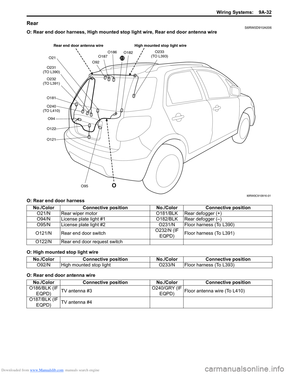
RearS6RW0D910A006
O: Rear end door harness, High mounted stop light wire, Rear end door antenna wire
O: Rear end door harness
O: High mounted stop light wire
O: Rear end door antenna wire
23
O231
(TO L390)
O232
(TO L391)
O181
O240
(TO L410)
O94
O122
O121
O95
O21
O92O187O186O182O233
(TO L393)
O
High mounted stop light wire Rear end door antenna wire
I6RW0C910916-01
No./Color Connective position No./Color Connective position
O21/N Rear wiper motor O181/BLK Rear defogger (+)
O94/N License plate light #1O182/BLK Rear defogger (–)
O95/N License plate light #2 O231/N Floor harness (To L390)
O121/N Rear end door switchO232/N (IF
EQPD)Floor harness (To L391)
O122/N Rear end door request switch
No./Color Connective position No./Color Connective position
O92/N High mounted stop light O233/N Floor harness (To L393)
No./Color Connective position No./Color Connective position
O186/BLK (IF
EQPD)TV antenna #3O240/GRY (IF
EQPD)Floor antenna wire (To L410)
O187/BLK (IF
EQPD)TV antenna #4