Page 1350 of 1556
Downloaded from www.Manualslib.com manuals search engine 9B-31 Lighting Systems:
Without initialization of the headlight auto leveling
system, it is not possible to obtain its proper function.
Also, if the headlight auto leveling system is not
initialized after replacing the headlight leveling control
module, the headlight leveling warning light in the
combination meter flashes.
1) Observe the following instructions.
• Park vehicle on level ground.
• Adjust air pressure of all tires to the specified
value respectively.
• Bounce vehicle body up and down by hand to
stabilize suspension.
2) Turn ignition switch to ON position.
3) Perform “Headlight Leveling Warning Light Check”.
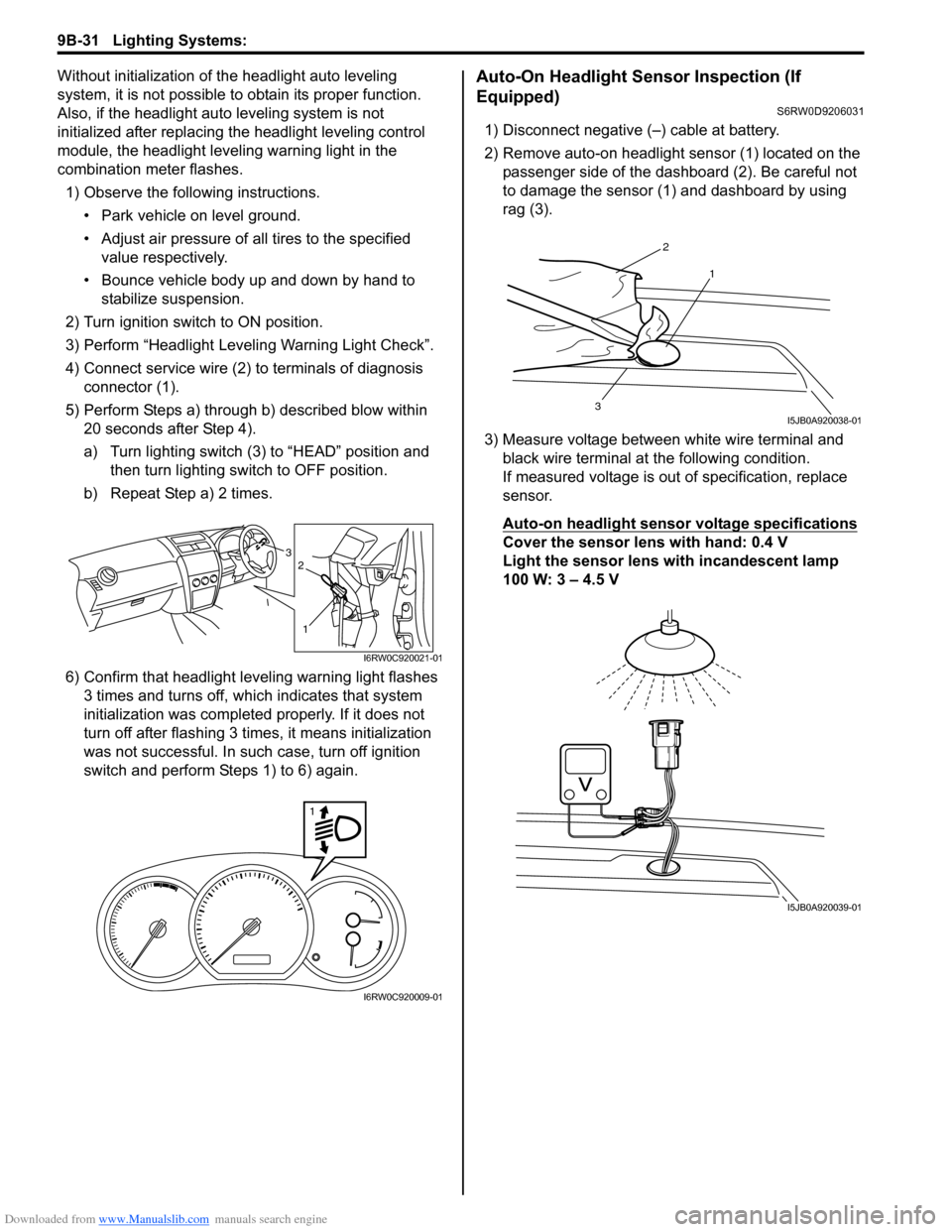
4) Connect service wire (2) to terminals of diagnosis
connector (1).
5) Perform Steps a) through b) described blow within
20 seconds after Step 4).
a) Turn lighting switch (3) to “HEAD” position and
then turn lighting switch to OFF position.
b) Repeat Step a) 2 times.
6) Confirm that headlight leveling warning light flashes
3 times and turns off, which indicates that system
initialization was completed properly. If it does not
turn off after flashing 3 times, it means initialization
was not successful. In such case, turn off ignition
switch and perform Steps 1) to 6) again.Auto-On Headlight Sensor Inspection (If
Equipped)
S6RW0D9206031
1) Disconnect negative (–) cable at battery.
2) Remove auto-on headlight sensor (1) located on the
passenger side of the dashboard (2). Be careful not
to damage the sensor (1) and dashboard by using
rag (3).
3) Measure voltage between white wire terminal and
black wire terminal at the following condition.
If measured voltage is out of specification, replace
sensor.
Auto-on headlight sensor voltage specifications
Cover the sensor lens with hand: 0.4 V
Light the sensor lens with incandescent lamp
100 W: 3 – 4.5 V3
1
2
I6RW0C920021-01
1
I6RW0C920009-01
2
1
3I5JB0A920038-01
I5JB0A920039-01
Page 1366 of 1556
Downloaded from www.Manualslib.com manuals search engine 9C-14 Instrumentation / Driver Info. / Horn:
Repair Instructions
Ignition Switch Removal and InstallationS6RW0D9306001
Removal
1) Disconnect negative cable at battery.
2) Confirm that ignition key is removed.
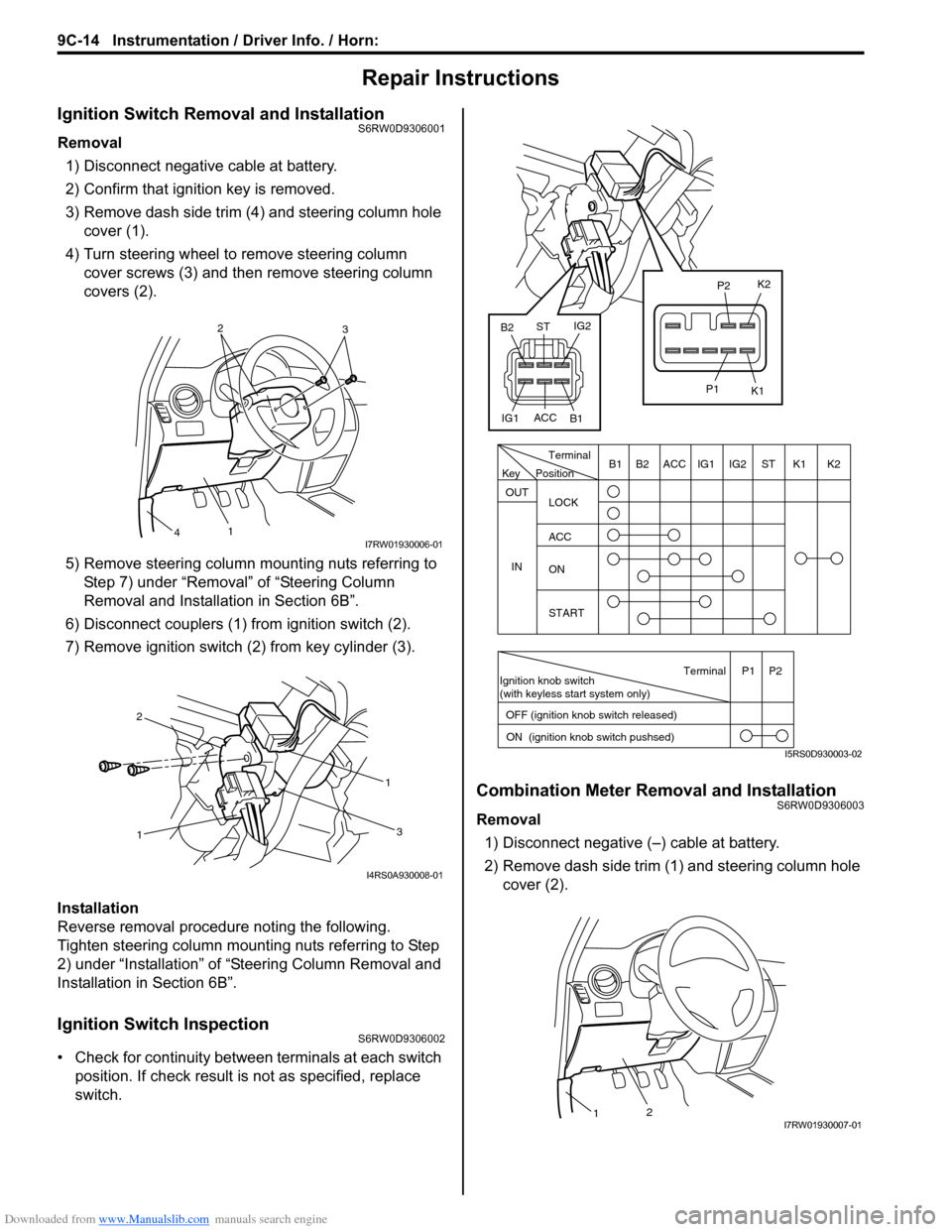
3) Remove dash side trim (4) and steering column hole
cover (1).
4) Turn steering wheel to remove steering column
cover screws (3) and then remove steering column
covers (2).
5) Remove steering column mounting nuts referring to
Step 7) under “Removal” of “Steering Column
Removal and Installation in Section 6B”.
6) Disconnect couplers (1) from ignition switch (2).
7) Remove ignition switch (2) from key cylinder (3).
Installation
Reverse removal procedure noting the following.
Tighten steering column mounting nuts referring to Step
2) under “Installation” of “Steering Column Removal and
Installation in Section 6B”.
Ignition Switch InspectionS6RW0D9306002
• Check for continuity between terminals at each switch
position. If check result is not as specified, replace
switch.
Combination Meter Removal and InstallationS6RW0D9306003
Removal
1) Disconnect negative (–) cable at battery.
2) Remove dash side trim (1) and steering column hole
cover (2).
2
3
1
4I7RW01930006-01
11
2
3
I4RS0A930008-01
PositionTerminal
LOCK
ACC
ON
START OUT
INK2 K1 ST IG2 IG1 ACC B1 B2
Ignition knob switch
(with keyless start system only)
ACC
IG1IG2
ST
B2
B1K2
K1
P2
P1
Terminal
OFF (ignition knob switch released)
ON (ignition knob switch pushsed)P1 P2
Key
I5RS0D930003-02
21I7RW01930007-01
Page 1369 of 1556
Downloaded from www.Manualslib.com manuals search engine Instrumentation / Driver Info. / Horn: 9C-17
Outside Air Temperature Sensor Removal and
Installation (If Equipped)
S6RW0D9306013
Removal
1) Disconnect negative (–) cable at battery.
2) Remove front bumper referring to “Front Bumper
and Rear Bumper Components in Section 9K”.
3) Disconnect connector from outside air temperature
sensor.
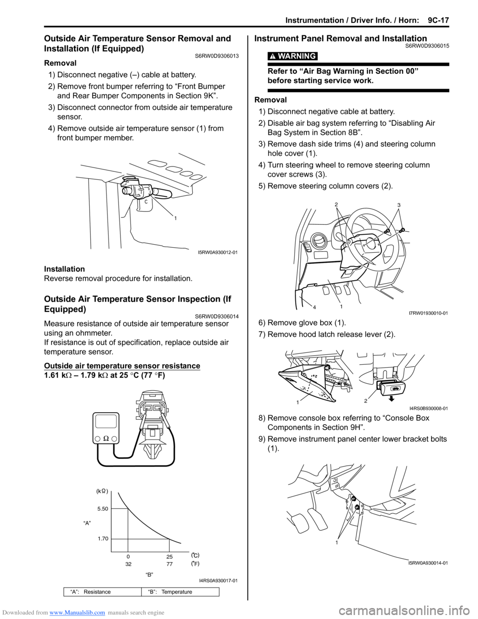
4) Remove outside air temperature sensor (1) from
front bumper member.
Installation
Reverse removal procedure for installation.
Outside Air Temperature Sensor Inspection (If
Equipped)
S6RW0D9306014
Measure resistance of outside air temperature sensor
using an ohmmeter.
If resistance is out of specification, replace outside air
temperature sensor.
Outside air temperature sensor resistance
1.61 kΩ – 1.79 kΩ at 25 °C (77 °F)
Instrument Panel Removal and InstallationS6RW0D9306015
WARNING!
Refer to “Air Bag Warning in Section 00”
before starting service work.
Removal
1) Disconnect negative cable at battery.
2) Disable air bag system referring to “Disabling Air
Bag System in Section 8B”.
3) Remove dash side trims (4) and steering column
hole cover (1).
4) Turn steering wheel to remove steering column
cover screws (3).
5) Remove steering column covers (2).
6) Remove glove box (1).
7) Remove hood latch release lever (2).
8) Remove console box referring to “Console Box
Components in Section 9H”.
9) Remove instrument panel center lower bracket bolts
(1).
“A”: Resistance “B”: Temperature
1
I5RW0A930012-01
“B” “A”5.50
1.70
0
3225
77
F
I4RS0A930017-01
2
3
1
4I7RW01930010-01
2
1I4RS0B930008-01
1
I5RW0A930014-01
Page 1501 of 1556
Downloaded from www.Manualslib.com manuals search engine Body Electrical Control System: 10B-28
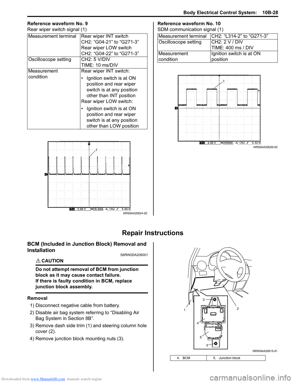
Reference waveform No. 9
Rear wiper switch signal (1)Reference waveform No. 10
SDM communication signal (1)
Repair Instructions
BCM (Included in Junction Block) Removal and
Installation
S6RW0DA206001
CAUTION!
Do not attempt removal of BCM from junction
block as it may cause contact failure.
If there is faulty condition in BCM, replace
junction block assembly.
Removal
1) Disconnect negative cable from battery.
2) Disable air bag system referring to “Disabling Air
Bag System in Section 8B”.
3) Remove dash side trim (1) and steering column hole
cover (2).
4) Remove junction block mounting nuts (3). Measurement terminal Rear wiper INT switch
CH2: “G04-21” to “G271-3”
Rear wiper LOW switch
CH2: “G04-22” to “G271-3”
Oscilloscope setting CH2: 5 V/DIV
TIME: 10 ms/DIV
Measurement
conditionRear wiper INT switch:
• Ignition switch is at ON
position and rear wiper
switch is at any position
other than INT position
Rear wiper LOW switch:
• Ignition switch is at ON
position and rear wiper
switch is at any position
other than LOW position
I4RS0AA20024-02
Measurement terminal CH2: “L314-2” to “G271-3”
Oscilloscope setting CH2: 2 V / DIV
TIME: 400 ms / DIV
Measurement
conditionIgnition switch is at ON
position
I4RS0AA20026-02
4. BCM 5. Junction block
2
1
3
3
4
5
I5RW0AA20015-01
Page 1521 of 1556
Downloaded from www.Manualslib.com manuals search engine Immobilizer Control System: 10C-19
Repair Instructions
ICM Removal and InstallationS6RW0DA306001
Removal
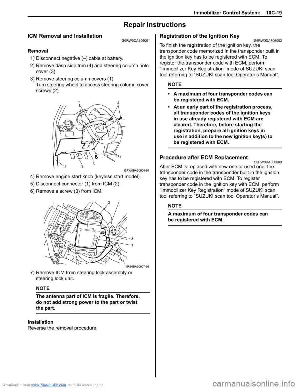
1) Disconnect negative (–) cable at battery.
2) Remove dash side trim (4) and steering column hole
cover (3).
3) Remove steering column covers (1).
Turn steering wheel to access steering column cover
screws (2).
4) Remove engine start knob (keyless start model).
5) Disconnect connector (1) from ICM (2).
6) Remove a screw (3) from ICM.
7) Remove ICM from steering lock assembly or
steering lock unit.
NOTE
The antenna part of ICM is fragile. Therefore,
do not add strong power to the part or twist
the part.
Installation
Reverse the removal procedure.
Registration of the Ignition KeyS6RW0DA306002
To finish the registration of the ignition key, the
transponder code memorized in the transponder built in
the ignition key has to be registered with ECM. To
register the transponder code with ECM, perform
“Immobilizer Key Registration” mode of SUZUKI scan
tool referring to “SUZUKI scan tool Operator’s Manual”.
NOTE
• A maximum of four transponder codes can
be registered with ECM.
• At an early part of the registration process,
all transponder codes of the ignition keys
in use already registered with ECM are
cleared. Therefore, before starting the
registration, prepare all ignition keys in
use in addition to the new ignition key(s) to
be registered with ECM.
Procedure after ECM ReplacementS6RW0DA306003
After ECM is replaced with new one or used one, the
transponder code in the transponder built in the ignition
key has to be registered with ECM. To register
transponder code in the ignition key with ECM, perform
“Immobilizer Key Registration” mode of SUZUKI scan
tool referring to “SUZUKI scan tool Operator’s Manual”.
NOTE
A maximum of four transponder codes can
be registered with ECM.
1
2
3
4I6RW0BA30004-01
2
3
1
I4RS0BA30007-03