2006 SUZUKI SX4 head
[x] Cancel search: headPage 1434 of 1556
Downloaded from www.Manualslib.com manuals search engine 9H-2 Interior Trim:
Head Lining Removal and InstallationS6RW0D9806002
WARNING!
Refer to “Air Bag System Service Warning in
Section 00” before starting service work.
Removal
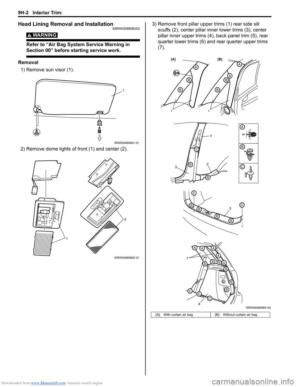
1) Remove sun visor (1).
2) Remove dome lights of front (1) and center (2).3) Remove front pillar upper trims (1) rear side sill
scuffs (2), center pillar inner lower trims (3), center
pillar inner upper trims (4), back panel trim (5), rear
quarter lower trims (6) and rear quarter upper trims
(7).
1
I5RW0A980001-01
12
I5RW0A980002-01
[A]: With curtain air bag [B]: Without curtain air bag
32
4
B
B
B
C
A
A
AB
B
A
B
B
[A] [B]
7
6
BBBA
A
AAA
B
B
B
CCC
5
C
BC
BB
B
11
C
I5RW0A980004-03
Page 1435 of 1556
Downloaded from www.Manualslib.com manuals search engine Interior Trim: 9H-3
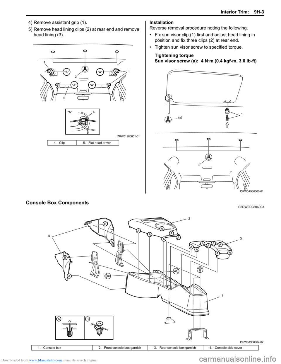
4) Remove assistant grip (1).
5) Remove head lining clips (2) at rear end and remove
head lining (3).Installation
Reverse removal procedure noting the following.
• Fix sun visor clip (1) first and adjust head lining in
position and fix three clips (2) at rear end.
• Tighten sun visor screw to specified torque.
Tightening torque
Sun visor screw (a): 4 N·m (0.4 kgf-m, 3.0 lb-ft)
Console Box ComponentsS6RW0D9806003 4. Clip 5. Flat head driver
“A”4
5
21 1
3“A”“A”
“A”“A”
I7RW01980001-01
2
1
(a)
I5RW0A980006-01
BA
B
A
A
B
AAA
AAA
A
AAAA
A
AA
2
3
1
4
I5RW0A980007-02
1. Console box 2. Front console box garnish 3. Rear console box garnish 4. Console side cover
Page 1438 of 1556
Downloaded from www.Manualslib.com manuals search engine 9J-2 Hood / Fenders / Doors:
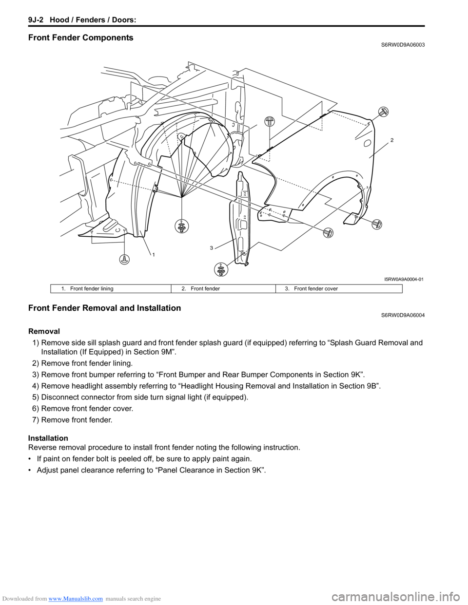
Front Fender ComponentsS6RW0D9A06003
Front Fender Removal and InstallationS6RW0D9A06004
Removal
1) Remove side sill splash guard and front fender splash guard (if equipped) referring to “Splash Guard Removal and
Installation (If Equipped) in Section 9M”.
2) Remove front fender lining.
3) Remove front bumper referring to “Front Bumper and Rear Bumper Components in Section 9K”.
4) Remove headlight assembly referring to “Headlight Housing Removal and Installation in Section 9B”.
5) Disconnect connector from side turn signal light (if equipped).
6) Remove front fender cover.
7) Remove front fender.
Installation
Reverse removal procedure to install front fender noting the following instruction.
• If paint on fender bolt is peeled off, be sure to apply paint again.
• Adjust panel clearance referring to “Panel Clearance in Section 9K”.
13
2
I5RW0A9A0004-01
1. Front fender lining 2. Front fender 3. Front fender cover
Page 1442 of 1556
Downloaded from www.Manualslib.com manuals search engine 9J-6 Hood / Fenders / Doors:
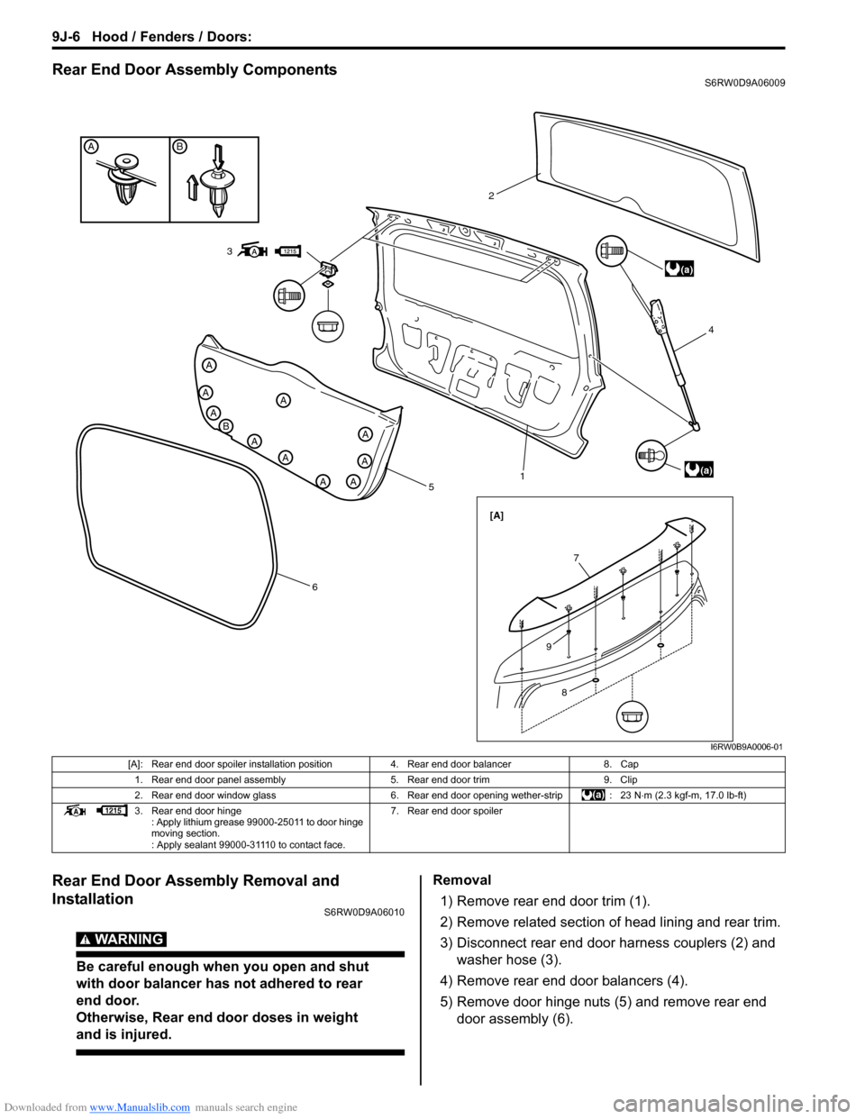
Rear End Door Assembly ComponentsS6RW0D9A06009
Rear End Door Assembly Removal and
Installation
S6RW0D9A06010
WARNING!
Be careful enough when you open and shut
with door balancer has not adhered to rear
end door.
Otherwise, Rear end door doses in weight
and is injured.
Removal
1) Remove rear end door trim (1).
2) Remove related section of head lining and rear trim.
3) Disconnect rear end door harness couplers (2) and
washer hose (3).
4) Remove rear end door balancers (4).
5) Remove door hinge nuts (5) and remove rear end
door assembly (6).
BA
A
B
A
A
A
A
A
AA
A
A
5
614 2
(a)
(a)
[A]
3
7
8
9
I6RW0B9A0006-01
[A]: Rear end door spoiler installation position 4. Rear end door balancer 8. Cap
1. Rear end door panel assembly 5. Rear end door trim 9. Clip
2. Rear end door window glass 6. Rear end door opening wether-strip : 23 N⋅m (2.3 kgf-m, 17.0 lb-ft)
3. Rear end door hinge
: Apply lithium grease 99000-25011 to door hinge
moving section.
: Apply sealant 99000-31110 to contact face.7. Rear end door spoiler
Page 1447 of 1556
Downloaded from www.Manualslib.com manuals search engine Body Structure: 9K-3
Specifications
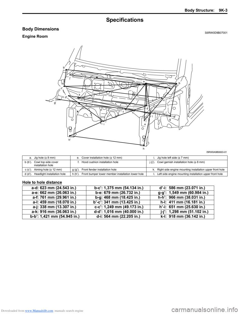
Body DimensionsS6RW0D9B07001
Engine Room
Hole to hole distance
ab
c
d
e
f
g
h
i
j
l
k
b'
c'
d'
g'
h'
j'
I5RW0A9B0003-01
a. Jig hole (φ 8 mm) e. Cover installation hole (φ 12 mm) i. Jig hole left side (φ 7 mm)
b (b’). Cowl top side cover
installation holef. Hood cushion installation hole j (j’). Cowl garnish installation hole (φ 8 mm)
c (c’). Aiming hole (φ 12 mm) g (g’). Front fender installation hole k. Right side engine mounting installation upper front hole
d (d’). Headlight installation hole h (h’). Front bumper lower member installation lower hole l. Left side engine mounting installation upper front hole
a-d: 623 mm (24.543 in.) b-c’: 1,375 mm (54.134 in.) d’-i: 586 mm (23.071 in.)
a-e: 662 mm (26.063 in.) b-e: 679 mm (26.732 in.) g-g’: 1,549 mm (60.984 in.)
a-f: 761 mm (29.961 in.) b-g: 468 mm (18.425 in.) h-h’: 966 mm (38.031 in.)
a-l: 459 mm (18.070 in.) b’-c’: 341 mm (13.425 in.) h-l: 411 mm (16.181 in.)
a-j: 338 mm (13.307 in.) c-c’: 1,249 mm (49.173 in.) h’-i: 651 mm (25.630 in.)
a-k: 916 mm (36.063 in.) d-d’: 1,016 mm (40.000 in.) j-j’: 1,298 mm (51.102 in.)
b-b’: 1,421 mm (54.945 in.) d-i: 564 mm (22.205 in.) k-l: 918 mm (36.142 in.)
Page 1478 of 1556
Downloaded from www.Manualslib.com manuals search engine 10B-5 Body Electrical Control System:
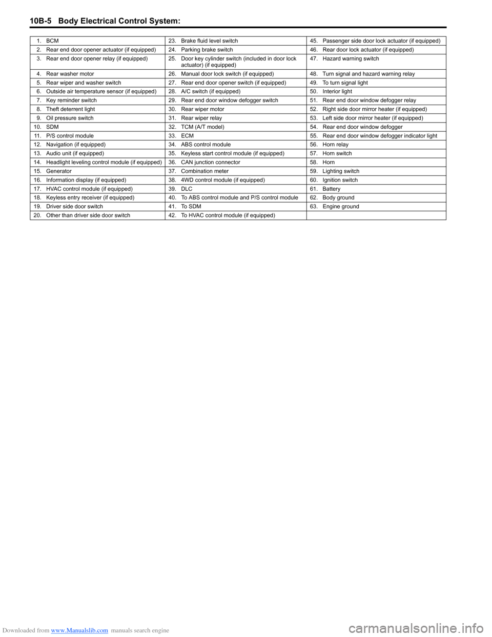
1. BCM 23. Brake fluid level switch 45. Passenger side door lock actuator (if equipped)
2. Rear end door opener actuator (if equipped) 24. Parking brake switch 46. Rear door lock actuator (if equipped)
3. Rear end door opener relay (if equipped) 25. Door key cylinder switch (included in door lock
actuator) (if equipped)47. Hazard warning switch
4. Rear washer motor 26. Manual door lock switch (if equipped) 48. Turn signal and hazard warning relay
5. Rear wiper and washer switch 27. Rear end door opener switch (if equipped) 49. To turn signal light
6. Outside air temperature sensor (if equipped) 28. A/C switch (if equipped) 50. Interior light
7. Key reminder switch 29. Rear end door window defogger switch 51. Rear end door window defogger relay
8. Theft deterrent light 30. Rear wiper motor 52. Right side door mirror heater (if equipped)
9. Oil pressure switch 31. Rear wiper relay 53. Left side door mirror heater (if equipped)
10. SDM 32. TCM (A/T model) 54. Rear end door window defogger
11. P/S control module 33. ECM 55. Rear end door window defogger indicator light
12. Navigation (if equipped) 34. ABS control module 56. Horn relay
13. Audio unit (if equipped) 35. Keyless start control module (if equipped) 57. Horn switch
14. Headlight leveling control module (if equipped) 36. CAN junction connector 58. Horn
15. Generator 37. Combination meter 59. Lighting switch
16. Information display (if equipped) 38. 4WD control module (if equipped) 60. Ignition switch
17. HVAC control module (if equipped) 39. DLC 61. Battery
18. Keyless entry receiver (if equipped) 40. To ABS control module and P/S control module 62. Body ground
19. Driver side door switch 41. To SDM 63. Engine ground
20. Other than driver side door switch 42. To HVAC control module (if equipped)
Page 1484 of 1556
Downloaded from www.Manualslib.com manuals search engine 10B-11 Body Electrical Control System:
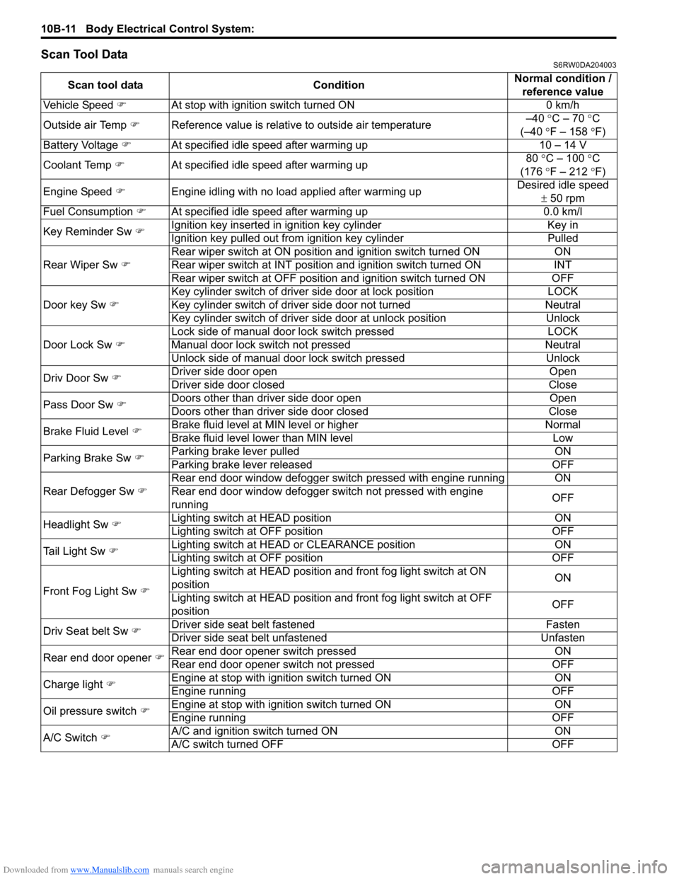
Scan Tool DataS6RW0DA204003
Scan tool data ConditionNormal condition /
reference value
Vehicle Speed �)At stop with ignition switch turned ON 0 km/h
Outside air Temp �)Reference value is relative to outside air temperature–40 °C – 70 °C
(–40 °F – 158 °F)
Battery Voltage �)At specified idle speed after warming up 10 – 14 V
Coolant Temp �)At specified idle speed after warming up80 °C – 100 °C
(176 °F – 212 °F)
Engine Speed �)Engine idling with no load applied after warming upDesired idle speed
± 50 rpm
Fuel Consumption �)At specified idle speed after warming up 0.0 km/l
Key Reminder Sw �)Ignition key inserted in ignition key cylinder Key in
Ignition key pulled out from ignition key cylinder Pulled
Rear Wiper Sw �)Rear wiper switch at ON position and ignition switch turned ON ON
Rear wiper switch at INT position and ignition switch turned ON INT
Rear wiper switch at OFF position and ignition switch turned ON OFF
Door key Sw �)Key cylinder switch of driver side door at lock position LOCK
Key cylinder switch of driver side door not turned Neutral
Key cylinder switch of driver side door at unlock position Unlock
Door Lock Sw �)Lock side of manual door lock switch pressed LOCK
Manual door lock switch not pressed Neutral
Unlock side of manual door lock switch pressed Unlock
Driv Door Sw �)Driver side door open Open
Driver side door closed Close
Pass Door Sw �)Doors other than driver side door open Open
Doors other than driver side door closed Close
Brake Fluid Level �)Brake fluid level at MIN level or higher Normal
Brake fluid level lower than MIN level Low
Parking Brake Sw �)Parking brake lever pulled ON
Parking brake lever released OFF
Rear Defogger Sw �)Rear end door window defogger switch pressed with engine running ON
Rear end door window defogger switch not pressed with engine
runningOFF
Headlight Sw �)Lighting switch at HEAD position ON
Lighting switch at OFF position OFF
Tail Light Sw �)Lighting switch at HEAD or CLEARANCE position ON
Lighting switch at OFF position OFF
Front Fog Light Sw �)Lighting switch at HEAD position and front fog light switch at ON
positionON
Lighting switch at HEAD position and front fog light switch at OFF
positionOFF
Driv Seat belt Sw
�)Driver side seat belt fastened Fasten
Driver side seat belt unfastened Unfasten
Rear end door opener �)Rear end door opener switch pressed ON
Rear end door opener switch not pressed OFF
Charge light �)Engine at stop with ignition switch turned ON ON
Engine running OFF
Oil pressure switch �)Engine at stop with ignition switch turned ON ON
Engine running OFF
A/C Switch �)A/C and ignition switch turned ON ON
A/C switch turned OFF OFF
Page 1485 of 1556
Downloaded from www.Manualslib.com manuals search engine Body Electrical Control System: 10B-12
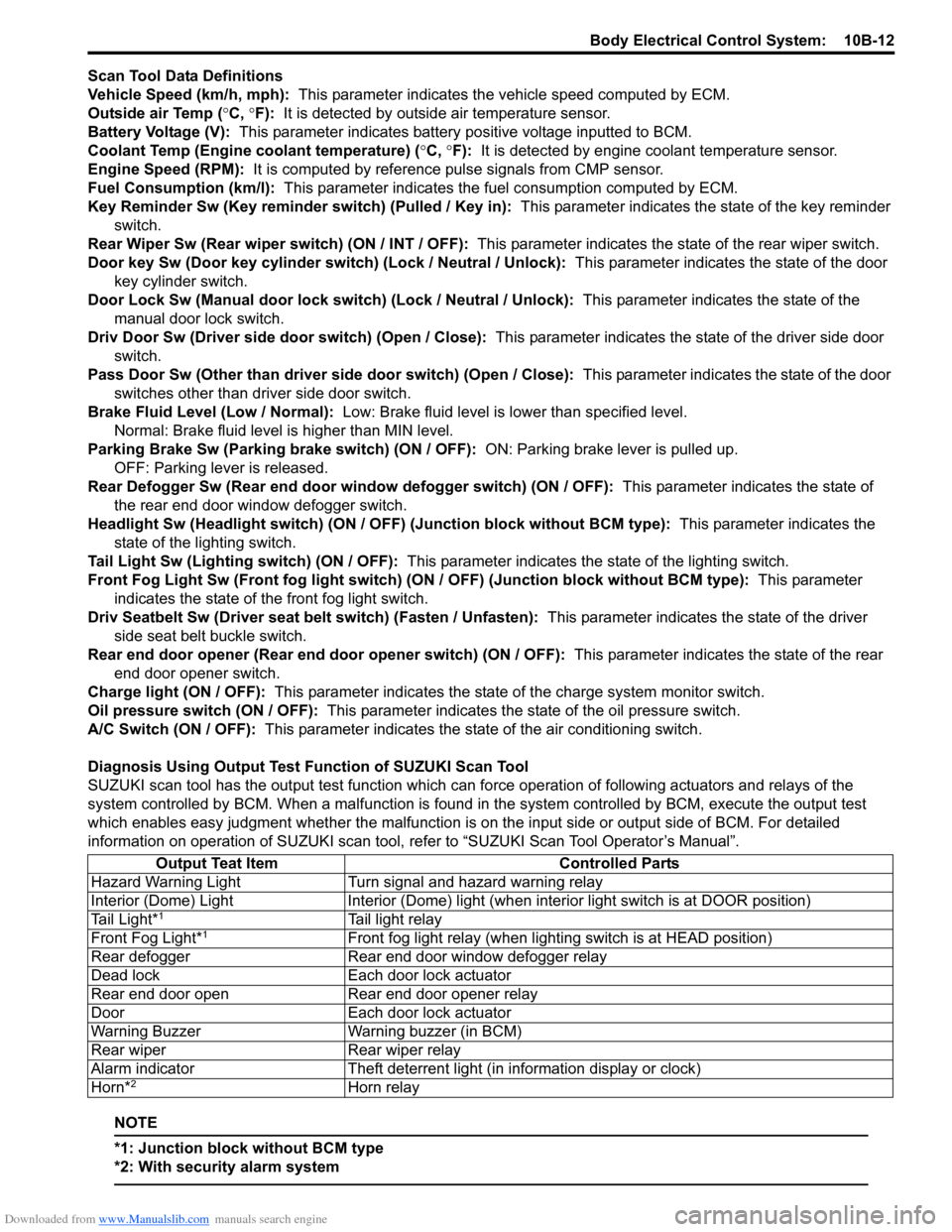
Scan Tool Data Definitions
Vehicle Speed (km/h, mph): This parameter indicates the vehicle speed computed by ECM.
Outside air Temp (°C, °F): It is detected by outside air temperature sensor.
Battery Voltage (V): This parameter indicates battery positive voltage inputted to BCM.
Coolant Temp (Engine coolant temperature) (°C, °F): It is detected by engine coolant temperature sensor.
Engine Speed (RPM): It is computed by reference pulse signals from CMP sensor.
Fuel Consumption (km/l): This parameter indicates the fuel consumption computed by ECM.
Key Reminder Sw (Key reminder switch) (Pulled / Key in): This parameter indicates the state of the key reminder
switch.
Rear Wiper Sw (Rear wiper switch) (ON / INT / OFF): This parameter indicates the state of the rear wiper switch.
Door key Sw (Door key cylinder switch) (Lock / Neutral / Unlock): This parameter indicates the state of the door
key cylinder switch.
Door Lock Sw (Manual door lock switch) (Lock / Neutral / Unlock): This parameter indicates the state of the
manual door lock switch.
Driv Door Sw (Driver side door switch) (Open / Close): This parameter indicates the state of the driver side door
switch.
Pass Door Sw (Other than driver side door switch) (Open / Close): This parameter indicates the state of the door
switches other than driver side door switch.
Brake Fluid Level (Low / Normal): Low: Brake fluid level is lower than specified level.
Normal: Brake fluid level is higher than MIN level.
Parking Brake Sw (Parking brake switch) (ON / OFF): ON: Parking brake lever is pulled up.
OFF: Parking lever is released.
Rear Defogger Sw (Rear end door window defogger switch) (ON / OFF): This parameter indicates the state of
the rear end door window defogger switch.
Headlight Sw (Headlight switch) (ON / OFF) (Junction block without BCM type): This parameter indicates the
state of the lighting switch.
Tail Light Sw (Lighting switch) (ON / OFF): This parameter indicates the state of the lighting switch.
Front Fog Light Sw (Front fog light switch) (ON / OFF) (Junction block without BCM type): This parameter
indicates the state of the front fog light switch.
Driv Seatbelt Sw (Driver seat belt switch) (Fasten / Unfasten): This parameter indicates the state of the driver
side seat belt buckle switch.
Rear end door opener (Rear end door opener switch) (ON / OFF): This parameter indicates the state of the rear
end door opener switch.
Charge light (ON / OFF): This parameter indicates the state of the charge system monitor switch.
Oil pressure switch (ON / OFF): This parameter indicates the state of the oil pressure switch.
A/C Switch (ON / OFF): This parameter indicates the state of the air conditioning switch.
Diagnosis Using Output Test Function of SUZUKI Scan Tool
SUZUKI scan tool has the output test function which can force operation of following actuators and relays of the
system controlled by BCM. When a malfunction is found in the system controlled by BCM, execute the output test
which enables easy judgment whether the malfunction is on the input side or output side of BCM. For detailed
information on operation of SUZUKI scan tool, refer to “SUZUKI Scan Tool Operator’s Manual”.
NOTE
*1: Junction block without BCM type
*2: With security alarm system
Output Teat Item Controlled Parts
Hazard Warning Light Turn signal and hazard warning relay
Interior (Dome) Light Interior (Dome) light (when interior light switch is at DOOR position)
Tail Light*
1Tail light relay
Front Fog Light*1Front fog light relay (when lighting switch is at HEAD position)
Rear defogger Rear end door window defogger relay
Dead lock Each door lock actuator
Rear end door open Rear end door opener relay
Door Each door lock actuator
Warning Buzzer Warning buzzer (in BCM)
Rear wiper Rear wiper relay
Alarm indicator Theft deterrent light (in information display or clock)
Horn*
2Horn relay