Page 794 of 1556
Downloaded from www.Manualslib.com manuals search engine 5A-146 Automatic Transmission/Transaxle:
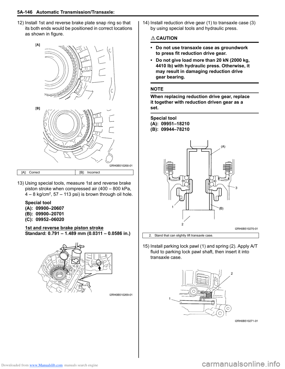
12) Install 1st and reverse brake plate snap ring so that
its both ends would be positioned in correct locations
as shown in figure.
13) Using special tools, measure 1st and reverse brake
piston stroke when compressed air (400 – 800 kPa,
4 – 8 kg/cm
2, 57 – 113 psi) is brown through oil hole.
Special tool
(A): 09900–20607
(B): 09900–20701
(C): 09952–06020
1st and reverse brake piston stroke
Standard: 0.791 – 1.489 mm (0.0311 – 0.0586 in.)14) Install reduction drive gear (1) to transaxle case (3)
by using special tools and hydraulic press.
CAUTION!
• Do not use transaxle case as groundwork
to press fit reduction drive gear.
• Do not give load more than 20 kN (2000 kg,
4410 lb) with hydraulic press. Otherwise, it
may result in damaging reduction drive
gear bearing.
NOTE
When replacing reduction drive gear, replace
it together with reduction driven gear as a
set.
Special tool
(A): 09951–18210
(B): 09944–78210
15) Install parking lock pawl (1) and spring (2). Apply A/T
fluid to parking lock pawl shaft, then insert it into
transaxle case.
[A]: Correct [B]: Incorrect
I2RH0B510268-01
I2RH0B510269-01
2. Stand that can slightly lift transaxle case.
I2RH0B510270-01
I2RH0B510271-01
Page 795 of 1556
Downloaded from www.Manualslib.com manuals search engine Automatic Transmission/Transaxle: 5A-147
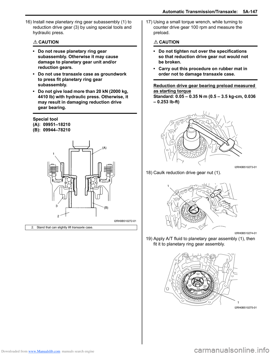
16) Install new planetary ring gear subassembly (1) to
reduction drive gear (3) by using special tools and
hydraulic press.
CAUTION!
• Do not reuse planetary ring gear
subassembly. Otherwise it may cause
damage to planetary gear unit and/or
reduction gears.
• Do not use transaxle case as groundwork
to press fit planetary ring gear
subassembly.
• Do not give load more than 20 kN (2000 kg,
4410 lb) with hydraulic press. Otherwise, it
may result in damaging reduction drive
gear bearing.
Special tool
(A): 09951–18210
(B): 09944–7821017) Using a small torque wrench, while turning to
counter drive gear 100 rpm and measure the
preload.
CAUTION!
• Do not tighten nut over the specifications
so that reduction drive gear nut would not
be broken.
• Carry out this procedure on rubber mat in
order not to damage transaxle case.
Reduction drive gear bearing preload measured
as starting torque
Standard: 0.05 – 0.35 N⋅m (0.5 – 3.5 kg-cm, 0.036
– 0.253 lb-ft)
18) Caulk reduction drive gear nut (1).
19) Apply A/T fluid to planetary gear assembly (1), then
fit it to planetary ring gear assembly.
2. Stand that can slightly lift transaxle case.
I2RH0B510272-01
I2RH0B510273-01
I2RH0B510274-01
1
I2RH0B510275-01
Page 813 of 1556
Downloaded from www.Manualslib.com manuals search engine Manual Transmission/Transaxle: 5B-1
Transmission / Transaxle
Manual Transmission/Transaxle
General Description
Manual Transaxle ConstructionS6RW0D5201001
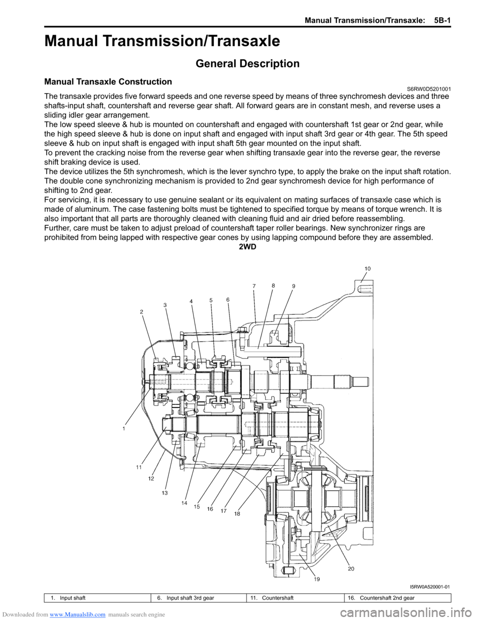
The transaxle provides five forward speeds and one reverse speed by means of three synchromesh devices and three
shafts-input shaft, countershaft and reverse gear shaft. All forward gears are in constant mesh, and reverse uses a
sliding idler gear arrangement.
The low speed sleeve & hub is mounted on countershaft and engaged with countershaft 1st gear or 2nd gear, while
the high speed sleeve & hub is done on input shaft and engaged with input shaft 3rd gear or 4th gear. The 5th speed
sleeve & hub on input shaft is engaged with input shaft 5th gear mounted on the input shaft.
To prevent the cracking noise from the reverse gear when shifting transaxle gear into the reverse gear, the reverse
shift braking device is used.
The device utilizes the 5th synchromesh, which is the lever synchro type, to apply the brake on the input shaft rotation.
The double cone synchronizing mechanism is provided to 2nd gear synchromesh device for high performance of
shifting to 2nd gear.
For servicing, it is necessary to use genuine sealant or its equivalent on mating surfaces of transaxle case which is
made of aluminum. The case fastening bolts must be tightened to specified torque by means of torque wrench. It is
also important that all parts are thoroughly cleaned with cleaning fluid and air dried before reassembling.
Further, care must be taken to adjust preload of countershaft taper roller bearings. New synchronizer rings are
prohibited from being lapped with respective gear cones by using lapping compound before they are assembled.
2WD
I5RW0A520001-01
1. Input shaft 6. Input shaft 3rd gear 11. Countershaft 16. Countershaft 2nd gear
Page 814 of 1556
Downloaded from www.Manualslib.com manuals search engine 5B-2 Manual Transmission/Transaxle:
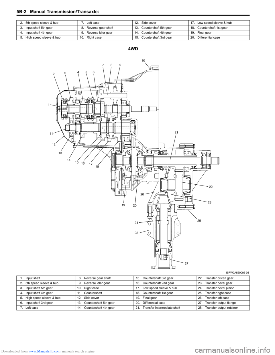
4WD
2. 5th speed sleeve & hub 7. Left case 12. Side cover 17. Low speed sleeve & hub
3. Input shaft 5th gear 8. Reverse gear shaft 13. Countershaft 5th gear 18. Countershaft 1st gear
4. Input shaft 4th gear 9. Reverse idler gear 14. Countershaft 4th gear 19. Final gear
5. High speed sleeve & hub 10. Right case 15. Countershaft 3rd gear 20. Differential case
I5RW0A520002-05
1. Input shaft 8. Reverse gear shaft 15. Countershaft 3rd gear 22. Transfer driven gear
2. 5th speed sleeve & hub 9. Reverse idler gear 16. Countershaft 2nd gear 23. Transfer bevel gear
3. Input shaft 5th gear 10. Right case 17. Low speed sleeve & hub 24. Transfer bevel pinion
4. Input shaft 4th gear 11. Countershaft 18. Countershaft 1st gear 25. Transfer right case
5. High speed sleeve & hub 12. Side cover 19. Final gear 26. Transfer left case
6. Input shaft 3rd gear 13. Countershaft 5th gear 20. Differential case 27. Transfer output flange
7. Left case 14. Countershaft 4th gear 21. Transfer intermediate shaft 28. Transfer output retainer
Page 815 of 1556
Downloaded from www.Manualslib.com manuals search engine Manual Transmission/Transaxle: 5B-3
Gear Shift Mechanism
The gear shifting control system consists of the following main parts. Movement of gear shift control lever is
transmitted to gear shift & select shaft through gear shift and gear select cables.
I5RW0A520003-02
1. Gear shift control cable 7. Reverse gear shift lever 13. Gear shift & select lever
2. Gear select control cable 8. 5th & reverse gear shift guide shaft 14. Low speed gear shift shaft
3. Select cable lever 9. 5th & reverse gear shift shaft 15. High speed gear shift shaft
4. Shift cable lever 10. Gear shift & select shaft assembly 16. Gear shift control lever assembly
5. 5th & reverse gear shift cam 11. 5th to reverse interlock guide bolt
6. 5th gear shift fork 12. Gear shift interlock bolt
Page 816 of 1556
Downloaded from www.Manualslib.com manuals search engine 5B-4 Manual Transmission/Transaxle:
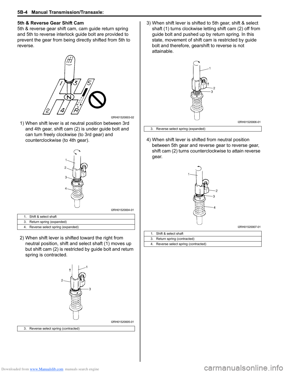
5th & Reverse Gear Shift Cam
5th & reverse gear shift cam, cam guide return spring
and 5th to reverse interlock guide bolt are provided to
prevent the gear from being directly shifted from 5th to
reverse.
1) When shift lever is at neutral position between 3rd
and 4th gear, shift cam (2) is under guide bolt and
can turn freely clockwise (to 3rd gear) and
counterclockwise (to 4th gear).
2) When shift lever is shifted toward the right from
neutral position, shift and select shaft (1) moves up
but shift cam (2) is restricted by guide bolt and return
spring is contracted.3) When shift lever is shifted to 5th gear, shift & select
shaft (1) turns clockwise letting shift cam (2) off from
guide bolt and pushed up by return spring. In this
state, movement of shift cam is restricted by guide
bolt and therefore, gearshift to reverse is not
attainable.
4) When shift lever is shifted from neutral position
between 5th gear and reverse gear to reverse gear,
shift cam (2) turns counterclockwise to attain reverse
gear.
1. Shift & select shaft
3. Return spring (expanded)
4. Reverse select spring (expanded)
3. Reverse select spring (contracted)
I2RH01520003-02
I2RH01520004-01
I2RH01520005-01
3. Reverse select spring (expanded)
1. Shift & select shaft
3. Return spring (contracted)
4. Reverse select spring (contracted)
I2RH01520006-01
I2RH01520007-01
Page 817 of 1556
Downloaded from www.Manualslib.com manuals search engine Manual Transmission/Transaxle: 5B-5
Diagnostic Information and Procedures
Manual Transaxle Symptom DiagnosisS6RW0D5204001
Repair Instructions
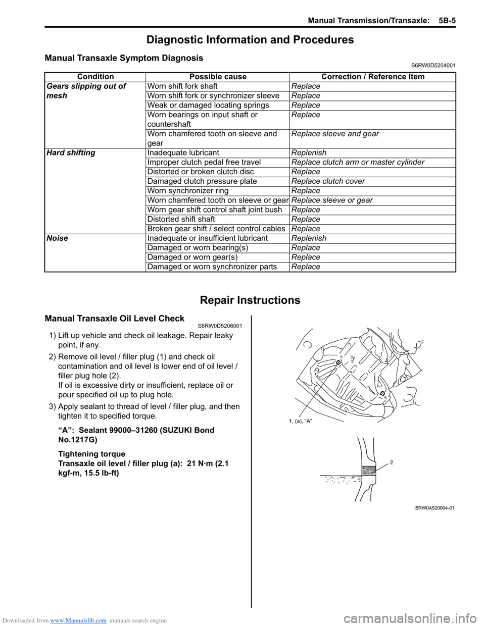
Manual Transaxle Oil Level CheckS6RW0D5206001
1) Lift up vehicle and check oil leakage. Repair leaky
point, if any.
2) Remove oil level / filler plug (1) and check oil
contamination and oil level is lower end of oil level /
filler plug hole (2).
If oil is excessive dirty or insufficient, replace oil or
pour specified oil up to plug hole.
3) Apply sealant to thread of level / filler plug, and then
tighten it to specified torque.
“A”: Sealant 99000–31260 (SUZUKI Bond
No.1217G)
Tightening torque
Transaxle oil level / filler plug (a): 21 N·m (2.1
kgf-m, 15.5 lb-ft)Condition Possible cause Correction / Reference Item
Gears slipping out of
meshWorn shift fork shaftReplace
Worn shift fork or synchronizer sleeveReplace
Weak or damaged locating springsReplace
Worn bearings on input shaft or
countershaftReplace
Worn chamfered tooth on sleeve and
gearReplace sleeve and gear
Hard shiftingInadequate lubricantReplenish
Improper clutch pedal free travelReplace clutch arm or master cylinder
Distorted or broken clutch discReplace
Damaged clutch pressure plateReplace clutch cover
Worn synchronizer ringReplace
Worn chamfered tooth on sleeve or gearReplace sleeve or gear
Worn gear shift control shaft joint bushReplace
Distorted shift shaftReplace
Broken gear shift / select control cablesReplace
NoiseInadequate or insufficient lubricantReplenish
Damaged or worn bearing(s)Replace
Damaged or worn gear(s)Replace
Damaged or worn synchronizer partsReplace
I5RW0A520004-01
Page 818 of 1556
Downloaded from www.Manualslib.com manuals search engine 5B-6 Manual Transmission/Transaxle:
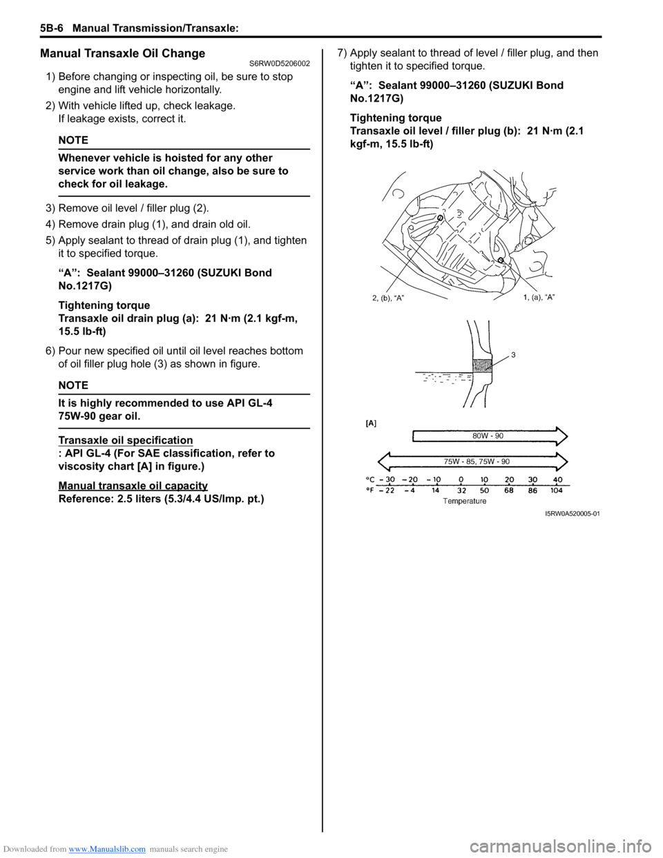
Manual Transaxle Oil ChangeS6RW0D5206002
1) Before changing or inspecting oil, be sure to stop
engine and lift vehicle horizontally.
2) With vehicle lifted up, check leakage.
If leakage exists, correct it.
NOTE
Whenever vehicle is hoisted for any other
service work than oil change, also be sure to
check for oil leakage.
3) Remove oil level / filler plug (2).
4) Remove drain plug (1), and drain old oil.
5) Apply sealant to thread of drain plug (1), and tighten
it to specified torque.
“A”: Sealant 99000–31260 (SUZUKI Bond
No.1217G)
Tightening torque
Transaxle oil drain plug (a): 21 N·m (2.1 kgf-m,
15.5 lb-ft)
6) Pour new specified oil until oil level reaches bottom
of oil filler plug hole (3) as shown in figure.
NOTE
It is highly recommended to use API GL-4
75W-90 gear oil.
Transaxle oil specification
: API GL-4 (For SAE classification, refer to
viscosity chart [A] in figure.)
Manual transaxle oil capacity
Reference: 2.5 liters (5.3/4.4 US/lmp. pt.)7) Apply sealant to thread of level / filler plug, and then
tighten it to specified torque.
“A”: Sealant 99000–31260 (SUZUKI Bond
No.1217G)
Tightening torque
Transaxle oil level / filler plug (b): 21 N·m (2.1
kgf-m, 15.5 lb-ft)
I5RW0A520005-01