2006 SUZUKI SX4 warning light
[x] Cancel search: warning lightPage 1359 of 1556
Downloaded from www.Manualslib.com manuals search engine Instrumentation / Driver Info. / Horn: 9C-7
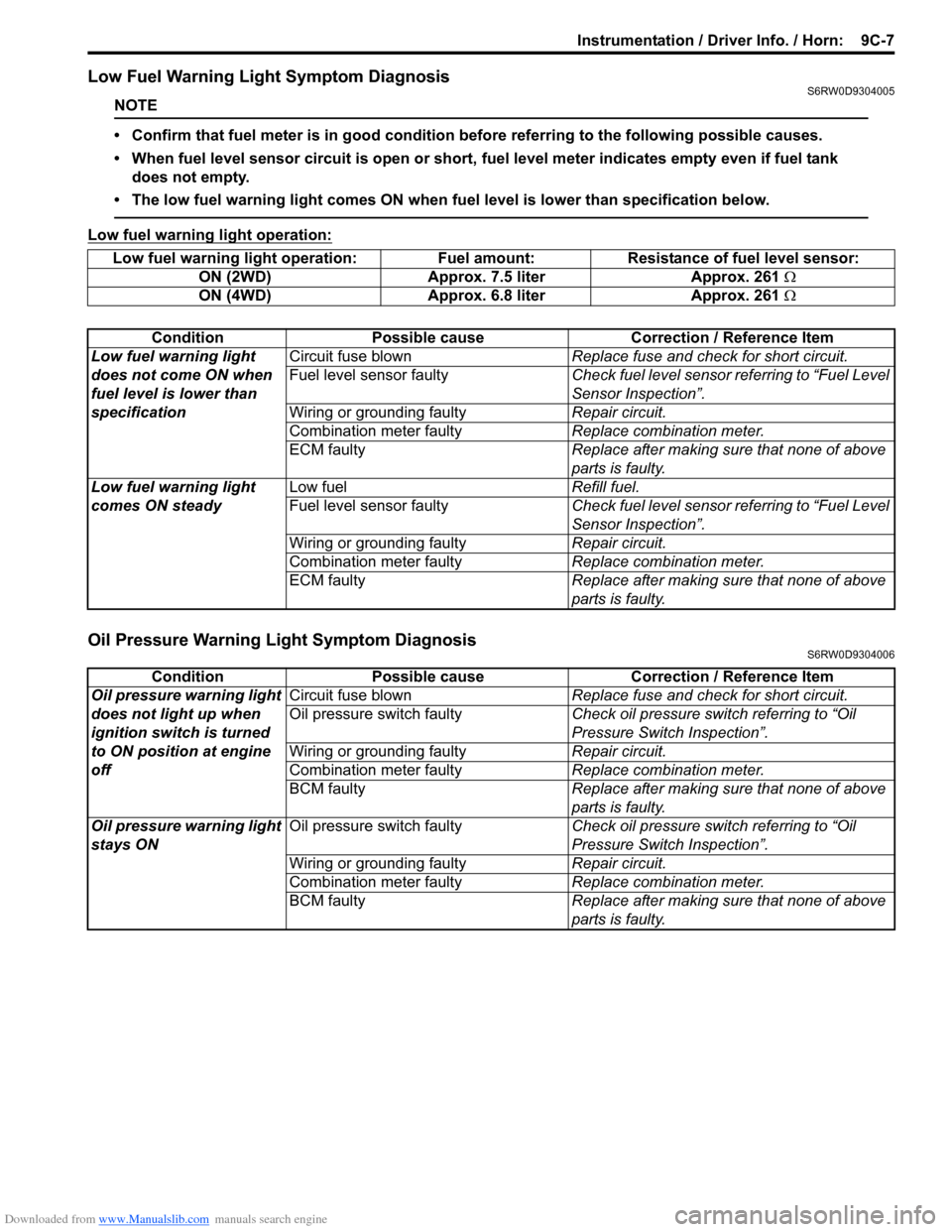
Low Fuel Warning Light Symptom DiagnosisS6RW0D9304005
NOTE
• Confirm that fuel meter is in good condition before referring to the following possible causes.
• When fuel level sensor circuit is open or short, fuel level meter indicates empty even if fuel tank
does not empty.
• The low fuel warning light comes ON when fuel level is lower than specification below.
Low fuel warning light operation:
Oil Pressure Warning Light Symptom DiagnosisS6RW0D9304006
Low fuel warning light operation: Fuel amount: Resistance of fuel level sensor:
ON (2WD) Approx. 7.5 liter Approx. 261 Ω
ON (4WD) Approx. 6.8 liter Approx. 261 Ω
Condition Possible cause Correction / Reference Item
Low fuel warning light
does not come ON when
fuel level is lower than
specificationCircuit fuse blownReplace fuse and check for short circuit.
Fuel level sensor faultyCheck fuel level sensor referring to “Fuel Level
Sensor Inspection”.
Wiring or grounding faultyRepair circuit.
Combination meter faultyReplace combination meter.
ECM faultyReplace after making sure that none of above
parts is faulty.
Low fuel warning light
comes ON steadyLow fuelRefill fuel.
Fuel level sensor faultyCheck fuel level sensor referring to “Fuel Level
Sensor Inspection”.
Wiring or grounding faultyRepair circuit.
Combination meter faultyReplace combination meter.
ECM faultyReplace after making sure that none of above
parts is faulty.
Condition Possible cause Correction / Reference Item
Oil pressure warning light
does not light up when
ignition switch is turned
to ON position at engine
offCircuit fuse blownReplace fuse and check for short circuit.
Oil pressure switch faultyCheck oil pressure switch referring to “Oil
Pressure Switch Inspection”.
Wiring or grounding faultyRepair circuit.
Combination meter faultyReplace combination meter.
BCM faultyReplace after making sure that none of above
parts is faulty.
Oil pressure warning light
stays ONOil pressure switch faultyCheck oil pressure switch referring to “Oil
Pressure Switch Inspection”.
Wiring or grounding faultyRepair circuit.
Combination meter faultyReplace combination meter.
BCM faultyReplace after making sure that none of above
parts is faulty.
Page 1360 of 1556
Downloaded from www.Manualslib.com manuals search engine 9C-8 Instrumentation / Driver Info. / Horn:
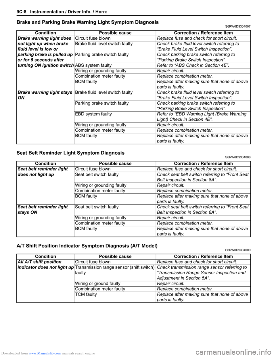
Brake and Parking Brake Warning Light Symptom DiagnosisS6RW0D9304007
Seat Belt Reminder Light Symptom DiagnosisS6RW0D9304008
A/T Shift Position Indicator Symptom Diagnosis (A/T Model)S6RW0D9304009
Condition Possible cause Correction / Reference Item
Brake warning light does
not light up when brake
fluid level is low or
parking brake is pulled up
or for 5 seconds after
turning ON ignition switchCircuit fuse blownReplace fuse and check for short circuit.
Brake fluid level switch faultyCheck brake fluid level switch referring to
“Brake Fluid Level Switch Inspection”.
Parking brake switch faultyCheck parking brake switch referring to
“Parking Brake Switch Inspection”.
ABS system faultyRefer to “ABS Check in Section 4E”.
Wiring or grounding faultyRepair circuit.
Combination meter faultyReplace combination meter.
BCM faultyReplace after making sure that none of above
parts is faulty.
Brake warning light stays
ONBrake fluid level switch faultyCheck brake fluid level switch referring to
“Brake Fluid Level Switch Inspection”.
Parking brake switch faultyCheck parking brake switch referring to
“Parking Brake Switch Inspection”.
EBD system faultyRefer to “EBD Warning Light (Brake Warning
Light) Check in Section 4E”.
Wiring or grounding faultyRepair circuit.
Combination meter faultyReplace combination meter.
BCM faultyReplace after making sure that none of above
parts is faulty.
Condition Possible cause Correction / Reference Item
Seat belt reminder light
does not light upCircuit fuse blownReplace fuse and check for short circuit.
Seat belt switch faultyCheck seat belt switch referring to “Front Seat
Belt Inspection in Section 8A”.
Wiring or grounding faultyRepair circuit.
Combination meter faultyReplace combination meter.
BCM faultyReplace after making sure that none of above
parts is faulty.
Seat belt reminder light
stays ONSeat belt switch faultyCheck seat belt switch referring to “Front Seat
Belt Inspection in Section 8A”.
Wiring or grounding faultyRepair circuit.
Combination meter faultyReplace combination meter.
BCM faultyReplace after making sure that none of above
parts is faulty.
Condition Possible cause Correction / Reference Item
All A/T shift position
indicator does not light upCircuit fuse blownReplace fuse and check for short circuit.
Transmission range sensor (shift switch)
faultyCheck transmission range sensor referring to
“Transmission Range Sensor Inspection and
Adjustment in Section 5A”.
Wiring or ground faultyRepair circuit.
Combination meter faultyReplace combination meter.
TCM faultyReplace after making sure that none of above
parts is faulty.
Page 1361 of 1556
Downloaded from www.Manualslib.com manuals search engine Instrumentation / Driver Info. / Horn: 9C-9
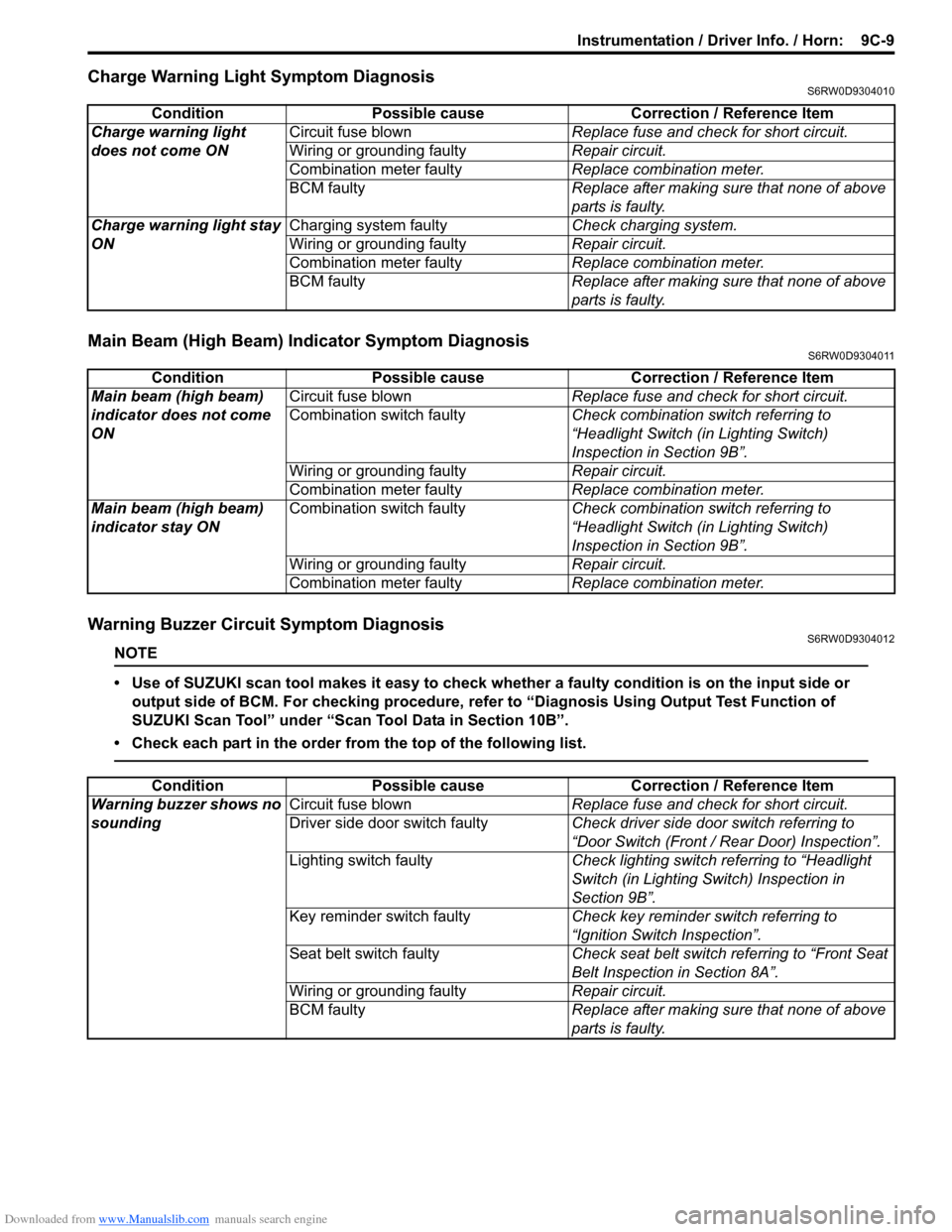
Charge Warning Light Symptom DiagnosisS6RW0D9304010
Main Beam (High Beam) Indicator Symptom DiagnosisS6RW0D9304011
Warning Buzzer Circuit Symptom DiagnosisS6RW0D9304012
NOTE
• Use of SUZUKI scan tool makes it easy to check whether a faulty condition is on the input side or
output side of BCM. For checking procedure, refer to “Diagnosis Using Output Test Function of
SUZUKI Scan Tool” under “Scan Tool Data in Section 10B”.
• Check each part in the order from the top of the following list.
Condition Possible cause Correction / Reference Item
Charge warning light
does not come ONCircuit fuse blownReplace fuse and check for short circuit.
Wiring or grounding faultyRepair circuit.
Combination meter faultyReplace combination meter.
BCM faulty Replace after making sure that none of above
parts is faulty.
Charge warning light stay
ONCharging system faultyCheck charging system.
Wiring or grounding faultyRepair circuit.
Combination meter faultyReplace combination meter.
BCM faulty Replace after making sure that none of above
parts is faulty.
Condition Possible cause Correction / Reference Item
Main beam (high beam)
indicator does not come
ONCircuit fuse blownReplace fuse and check for short circuit.
Combination switch faultyCheck combination switch referring to
“Headlight Switch (in Lighting Switch)
Inspection in Section 9B”.
Wiring or grounding faultyRepair circuit.
Combination meter faultyReplace combination meter.
Main beam (high beam)
indicator stay ONCombination switch faultyCheck combination switch referring to
“Headlight Switch (in Lighting Switch)
Inspection in Section 9B”.
Wiring or grounding faultyRepair circuit.
Combination meter faultyReplace combination meter.
Condition Possible cause Correction / Reference Item
Warning buzzer shows no
soundingCircuit fuse blownReplace fuse and check for short circuit.
Driver side door switch faultyCheck driver side door switch referring to
“Door Switch (Front / Rear Door) Inspection”.
Lighting switch faultyCheck lighting switch referring to “Headlight
Switch (in Lighting Switch) Inspection in
Section 9B”.
Key reminder switch faultyCheck key reminder switch referring to
“Ignition Switch Inspection”.
Seat belt switch faultyCheck seat belt switch referring to “Front Seat
Belt Inspection in Section 8A”.
Wiring or grounding faultyRepair circuit.
BCM faultyReplace after making sure that none of above
parts is faulty.
Page 1415 of 1556
Downloaded from www.Manualslib.com manuals search engine Security and Locks: 9F-4
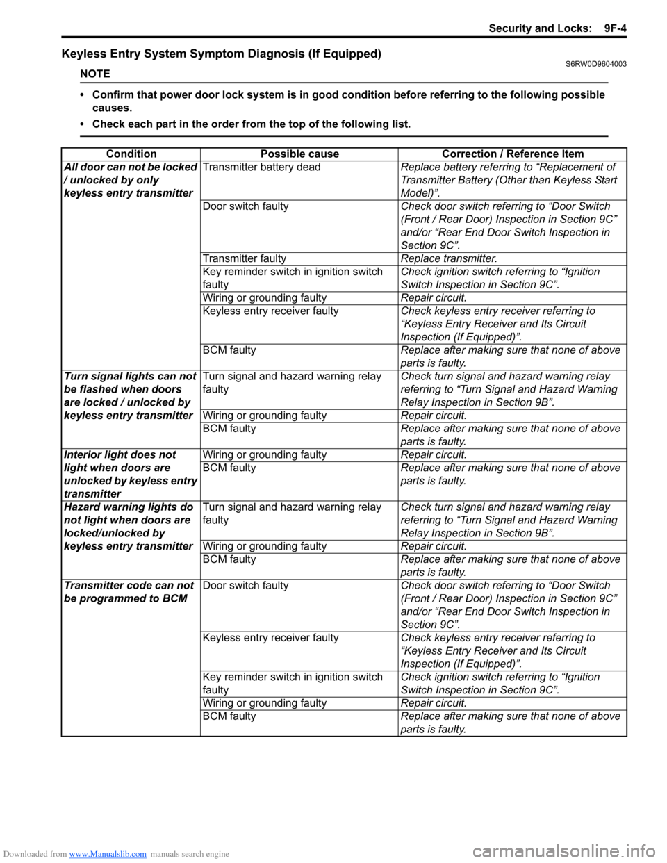
Keyless Entry System Symptom Diagnosis (If Equipped)S6RW0D9604003
NOTE
• Confirm that power door lock system is in good condition before referring to the following possible
causes.
• Check each part in the order from the top of the following list.
Condition Possible cause Correction / Reference Item
All door can not be locked
/ unlocked by only
keyless entry transmitterTransmitter battery deadReplace battery referring to “Replacement of
Transmitter Battery (Other than Keyless Start
Model)”.
Door switch faultyCheck door switch referring to “Door Switch
(Front / Rear Door) Inspection in Section 9C”
and/or “Rear End Door Switch Inspection in
Section 9C”.
Transmitter faultyReplace transmitter.
Key reminder switch in ignition switch
faultyCheck ignition switch referring to “Ignition
Switch Inspection in Section 9C”.
Wiring or grounding faultyRepair circuit.
Keyless entry receiver faultyCheck keyless entry receiver referring to
“Keyless Entry Receiver and Its Circuit
Inspection (If Equipped)”.
BCM faultyReplace after making sure that none of above
parts is faulty.
Turn signal lights can not
be flashed when doors
are locked / unlocked by
keyless entry transmitterTurn signal and hazard warning relay
faultyCheck turn signal and hazard warning relay
referring to “Turn Signal and Hazard Warning
Relay Inspection in Section 9B”.
Wiring or grounding faultyRepair circuit.
BCM faultyReplace after making sure that none of above
parts is faulty.
Interior light does not
light when doors are
unlocked by keyless entry
transmitterWiring or grounding faultyRepair circuit.
BCM faultyReplace after making sure that none of above
parts is faulty.
Hazard warning lights do
not light when doors are
locked/unlocked by
keyless entry transmitterTurn signal and hazard warning relay
faultyCheck turn signal and hazard warning relay
referring to “Turn Signal and Hazard Warning
Relay Inspection in Section 9B”.
Wiring or grounding faultyRepair circuit.
BCM faultyReplace after making sure that none of above
parts is faulty.
Transmitter code can not
be programmed to BCMDoor switch faultyCheck door switch referring to “Door Switch
(Front / Rear Door) Inspection in Section 9C”
and/or “Rear End Door Switch Inspection in
Section 9C”.
Keyless entry receiver faultyCheck keyless entry receiver referring to
“Keyless Entry Receiver and Its Circuit
Inspection (If Equipped)”.
Key reminder switch in ignition switch
faultyCheck ignition switch referring to “Ignition
Switch Inspection in Section 9C”.
Wiring or grounding faultyRepair circuit.
BCM faultyReplace after making sure that none of above
parts is faulty.
Page 1425 of 1556
Downloaded from www.Manualslib.com manuals search engine Security and Locks: 9F-14
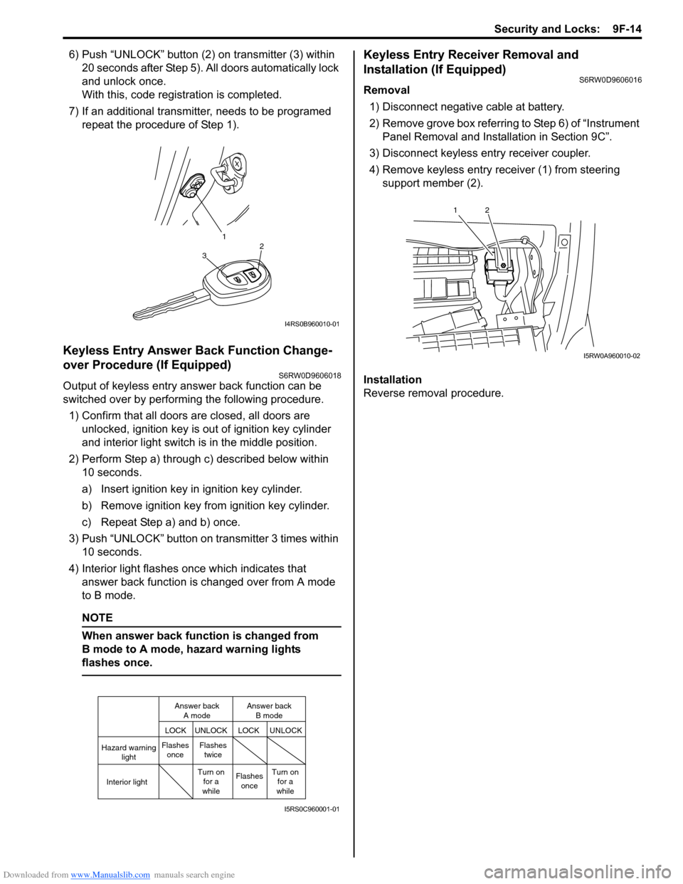
6) Push “UNLOCK” button (2) on transmitter (3) within
20 seconds after Step 5). All doors automatically lock
and unlock once.
With this, code registration is completed.
7) If an additional transmitter, needs to be programed
repeat the procedure of Step 1).
Keyless Entry Answer Back Function Change-
over Procedure (If Equipped)
S6RW0D9606018
Output of keyless entry answer back function can be
switched over by performing the following procedure.
1) Confirm that all doors are closed, all doors are
unlocked, ignition key is out of ignition key cylinder
and interior light switch is in the middle position.
2) Perform Step a) through c) described below within
10 seconds.
a) Insert ignition key in ignition key cylinder.
b) Remove ignition key from ignition key cylinder.
c) Repeat Step a) and b) once.
3) Push “UNLOCK” button on transmitter 3 times within
10 seconds.
4) Interior light flashes once which indicates that
answer back function is changed over from A mode
to B mode.
NOTE
When answer back function is changed from
B mode to A mode, hazard warning lights
flashes once.
Keyless Entry Receiver Removal and
Installation (If Equipped)
S6RW0D9606016
Removal
1) Disconnect negative cable at battery.
2) Remove grove box referring to Step 6) of “Instrument
Panel Removal and Installation in Section 9C”.
3) Disconnect keyless entry receiver coupler.
4) Remove keyless entry receiver (1) from steering
support member (2).
Installation
Reverse removal procedure.
1
32
I4RS0B960010-01
Hazard warning
light
LOCK LOCKUNLOCK UNLOCK
Interior lightFlashes
onceFlashes
twice
Flashes
once Turn on
for a
whileTurn on
for a
while Answer back
A modeAnswer back
B mode
I5RS0C960001-01
12
I5RW0A960010-02
Page 1434 of 1556
Downloaded from www.Manualslib.com manuals search engine 9H-2 Interior Trim:
Head Lining Removal and InstallationS6RW0D9806002
WARNING!
Refer to “Air Bag System Service Warning in
Section 00” before starting service work.
Removal
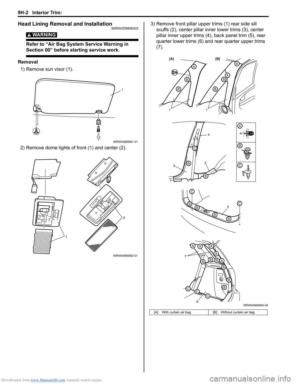
1) Remove sun visor (1).
2) Remove dome lights of front (1) and center (2).3) Remove front pillar upper trims (1) rear side sill
scuffs (2), center pillar inner lower trims (3), center
pillar inner upper trims (4), back panel trim (5), rear
quarter lower trims (6) and rear quarter upper trims
(7).
1
I5RW0A980001-01
12
I5RW0A980002-01
[A]: With curtain air bag [B]: Without curtain air bag
32
4
B
B
B
C
A
A
AB
B
A
B
B
[A] [B]
7
6
BBBA
A
AAA
B
B
B
CCC
5
C
BC
BB
B
11
C
I5RW0A980004-03
Page 1474 of 1556
Downloaded from www.Manualslib.com manuals search engine 10B-1 Body Electrical Control System:
Control Systems
Body Electrical Control System
Precautions
Precautions in Diagnosing TroubleS6RW0DA200001
• Diagnostic information stored in BCM memory can be cleared as well as checked by using SUZUKI scan tool.
Before using scan tool, read its Operator’s (Instruction) Manual carefully to have good understanding as to what
functions are available and how to use it.
• Be sure to read “Precautions for Electrical Circuit Service in Section 00” before inspection and observe what is
written there.
• Communication of ECM, TCM (A/T model), ABS control module, 4WD control module (if equipped), keyless start
control module (if equipped), combination meter and BCM is established by CAN (Controller Area Network). For
detail of CAN communication for BCM, refer to “CAN Communication System Description”. Therefore, handle CAN
communication line with care referring to “Precaution for CAN Communication System in Section 00”.
General Description
BCM General DescriptionS6RW0DA201001
The Body electrical Control Module (BCM) is
incorporated in junction block. Do not attempt removal of
BCM from junction block as it may cause contact failure.
The BCM incorporates relays and controllers which are
used for the following systems and controls them.
• Power door lock (if equipped)
• Keyless entry (if equipped)
• Door lock function of keyless start system (if
equipped)
• Rear wiper
• Combination meter
• Interior light• Warning buzzer
• Rear end door window defogger and door mirror
heater (if equipped)
• Rear end door opener (if equipped)
• Theft deterrent light
Also, the BCM has a function to cause the interior light
and open door warning light in the combination meter to
turn off when any door is left open for longer than 15
minutes to reduce wasteful battery consumption.
In addition, it is possible to check operation of actuator
which is controlled by BCM by using the output test
function of SUZUKI scan tool to operate actuator
simulatively.
CAN Communication System DescriptionS6RW0DA201002
Refer to “CAN Communication System Description in Section 1A” for CAN communication system description.
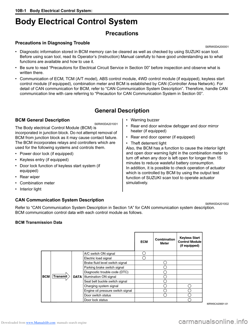
BCM communication control data with each control module as follows.
BCM Transmission Data
A/C switch ON signal
Electric load signal
Brake fluid level switch signal
Parking brake switch signal
Diagnostic trouble code (DTC)
Illumination ON signal
Seat belt buckle switch signal
Charging system signal
Engine oil pressure switch signal
Door switch status
Door lock statusECMKeyless Start
Control Module
(if equipped) Combination
Meter
BCMTransmit
DATA
I6RW0CA20001-01
Page 1475 of 1556
Downloaded from www.Manualslib.com manuals search engine Body Electrical Control System: 10B-2
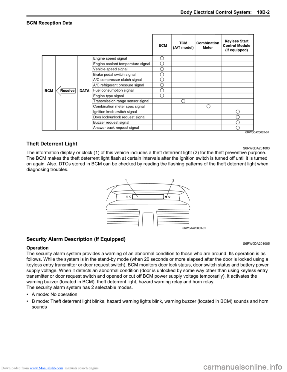
BCM Reception Data
Theft Deterrent LightS6RW0DA201003
The information display or clock (1) of this vehicle includes a theft deterrent light (2) for the theft preventive purpose.
The BCM makes the theft deterrent light flash at certain intervals after the ignition switch is turned off until it is turned
on again. Also, DTCs stored in BCM can be checked by reading the flashing patterns of the theft deterrent light when
diagnosing troubles.
Security Alarm Description (If Equipped)S6RW0DA201005
Operation
The security alarm system provides a warning of an abnormal condition to those who are around. Its operation is as
follows. While the system is in the stand-by mode (when 20 seconds or more elapsed after the door is locked using a
keyless entry transmitter or door request switch), BCM monitors door lock status, door switch status and battery power
supply voltage. When it detects an abnormal condition (door is unlocked by some way other than using keyless entry
transmitter or door request switch and opened or cut off BCM power supply voltage temporarily), it activates the
warning buzzer (located in BCM), theft deterrent light, hazard warning relay and horn relay.
The security alarm system has 2 selectable modes.
• A mode: No operation
• B mode: Theft deterrent light blinks, hazard warning lights blink, warning buzzer (located in BCM) sounds and horn
sounds
Engine speed signal
Vehicle speed signal Engine coolant temperature signal
Brake pedal switch signal
A/C refrigerant pressure signal
Fuel consumption signal A/C compressor clutch signal
Engine type signal
Transmission range sensor signal
Combination meter spec signal
Ignition knob switch signal
Door lock/unlock request signal
Buzzer request signal
Answer back request signal DATA BCM
Receive
Combination
Meter TCM
(A/T model)Keyless Start
Control Module
(if equipped) ECM
I6RW0CA20002-01
12
I5RW0AA20003-01