2006 SUZUKI SX4 ECU
[x] Cancel search: ECUPage 1153 of 1556
Downloaded from www.Manualslib.com manuals search engine Air Bag System: 8B-114
21) Wash your hands with mild soap and water
afterward.
NOTE
Remaining steps are to be followed in the
unlikely event that air bag (inflator) module
did not deploy or seat belt pretensioner did
not activate.
22) Ensure that deployment harness has been
disconnected from 12 volts vehicle battery and that
its two banana plugs have been shorted together by
fully seating one banana plug into the other.
23) Disconnect deployment harness and adapter cable
from air bag (inflator) module or seat belt
pretensioner.
24) Temporarily store undeployed air bag (inflator)
module referring to “Precautions on Service and
Diagnosis of Air Bag System” for details.
25) Contact your local distributor for further assistance.
Deployment / Activation Inside of Vehicle
When the vehicle will be destroyed, or salvaged for
component parts, deploy the air bag modules and/or
activate seat belt pretensioners installed on vehicle.
NOTE
If equipped with the seat belt pretensioners,
activate both side of seat belt pretensioners
at the same time when using special tool (C).
1) Turn ignition switch to LOCK position, remove key
and put on safety glasses.
2) Remove all loose objects from front seats and
instrument panel.
3) Disconnect air bag (inflator) module or seat belt
pretensioner connector as follows.
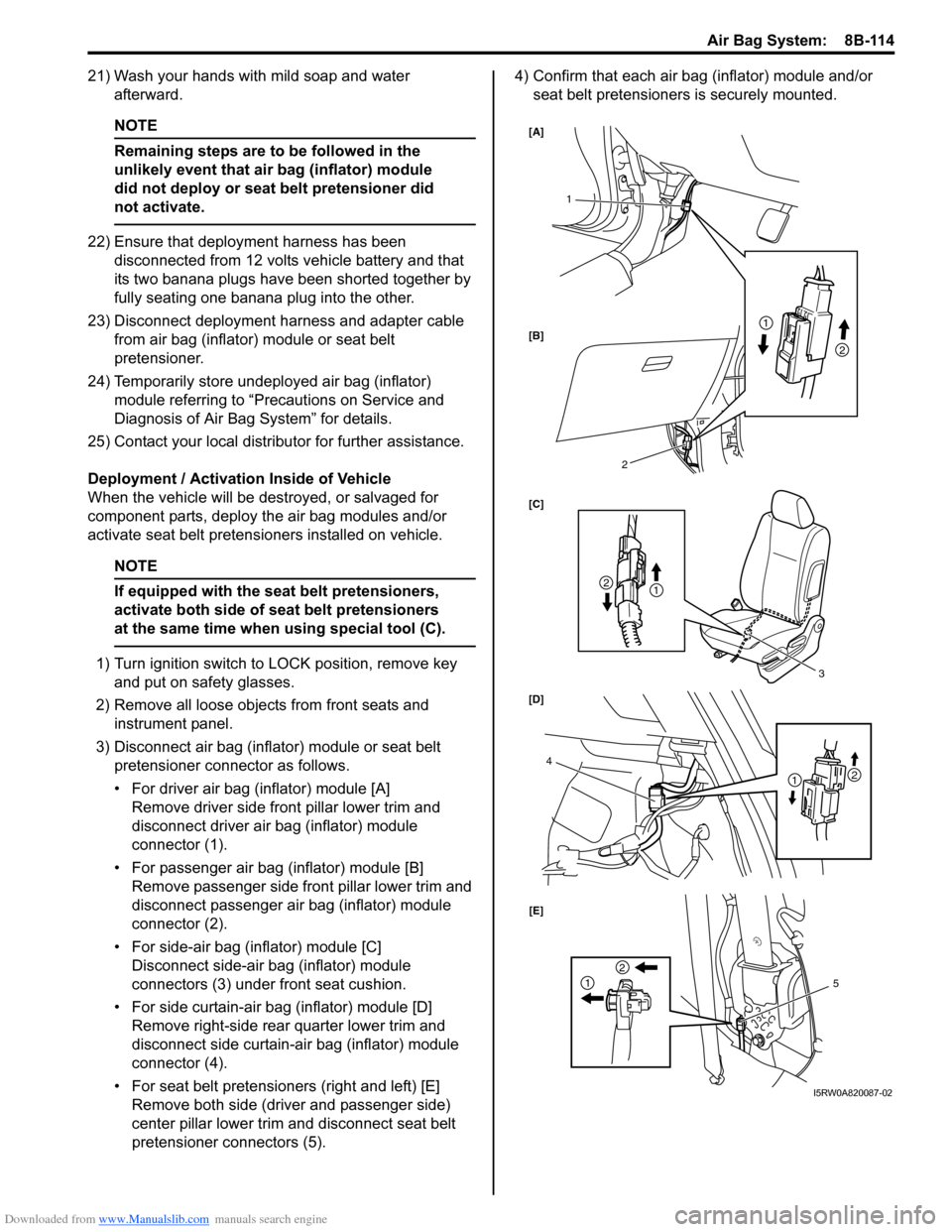
• For driver air bag (inflator) module [A]
Remove driver side front pillar lower trim and
disconnect driver air bag (inflator) module
connector (1).
• For passenger air bag (inflator) module [B]
Remove passenger side front pillar lower trim and
disconnect passenger air bag (inflator) module
connector (2).
• For side-air bag (inflator) module [C]
Disconnect side-air bag (inflator) module
connectors (3) under front seat cushion.
• For side curtain-air bag (inflator) module [D]
Remove right-side rear quarter lower trim and
disconnect side curtain-air bag (inflator) module
connector (4).
• For seat belt pretensioners (right and left) [E]
Remove both side (driver and passenger side)
center pillar lower trim and disconnect seat belt
pretensioner connectors (5).4) Confirm that each air bag (inflator) module and/or
seat belt pretensioners is securely mounted.
1
3
4
2
1
21
2
21
2
15 [A]
[B]
[C]
[D]
[E]
I5RW0A820087-02
Page 1164 of 1556
Downloaded from www.Manualslib.com manuals search engine 9-iv Table of Contents
Front Speaker Removal and Installation (If
Equipped) ........................................................9C-19
Rear Speaker Removal and Installation (If
Equipped) ........................................................9C-19
GPS Antenna Removal and Installation (If
Equipped) ........................................................9C-20
Horn Removal and Installation ..........................9C-20
Horn Inspection .................................................9C-20
Horn Relay Inspection .......................................9C-20
Antenna Base Removal and Installation ...........9C-21
Remote Audio Control Switch Removal and
Installation (If Equipped) .................................9C-21
Remote Audio Control Switch Inspection (If
Equipped) ........................................................9C-22
Vehicle Speed Signal Inspection (For Audio
Unit) (If Equipped) ...........................................9C-22
Specifications .....................................................9C-22
Tightening Torque Specifications ......................9C-22
Wipers / Washers .................................... 9D-1
Diagnostic Information and Procedures ............ 9D-1
Front Wiper and Washer Symptom Diagnosis ....9D-1
Rear Wiper and Washer Symptom Diagnosis..... 9D-1
Repair Instructions ..............................................9D-2
Wipers and Washers Components .....................9D-2
Washer Tank and Washer Pump Removal
and Installation ..................................................9D-3
Washer Pump Inspection ....................................9D-3
Windshield Wiper Removal and Installation ........9D-3
Windshield Wiper Motor Inspection.....................9D-4
Rear Wiper Removal and Installation.................. 9D-6
Rear Wiper Motor Inspection ..............................9D-7
Windshield Wiper and Washer Switch
Removal and Installation ................................... 9D-8
Windshield Wiper and Washer Switch
Inspection .......................................................... 9D-8
Rear Wiper and Washer Switch Removal and
Installation .......................................................9D-10
Rear Wiper and Washer Switch Inspection.......9D-10
Rear Wiper Relay Removal and Installation .....9D-10
Rear Wiper Relay Inspection ............................9D-10
Specifications .....................................................9D-11
Tightening Torque Specifications ......................9D-11
Glass / Windows / Mirrors .......................9E-1
Precautions........................................................... 9E-1
Precautions for Power Window Service
(Pinching Prevention Function Model) .............. 9E-1
General Description ............................................. 9E-1
Rear End Door Window Defogger System
Description ........................................................ 9E-1
Schematic and Routing Diagram ........................ 9E-2
Power Window Circuit Diagram (Pinching
Prevention Function Model) .............................. 9E-2
Diagnostic Information and Procedures ............ 9E-3
Rear End door Window Defogger Symptom
Diagnosis .......................................................... 9E-3
Power Window Control System Symptom
Diagnosis .......................................................... 9E-3Inspection of Pinching Prevention Function
(Pinching Prevention Function Model) .............. 9E-4
Power Door Mirror Control System Symptom
Diagnosis .......................................................... 9E-4
Door Mirror Heater Symptom Diagnosis (If
Equipped) .......................................................... 9E-5
Repair Instructions .............................................. 9E-5
Windshield Components ..................................... 9E-5
Windshield Removal and Installation .................. 9E-6
Front Pillar Window Components...................... 9E-10
Front Pillar Window Removal and Installation... 9E-10
Rear Quarter Window Components .................. 9E-11
Rear Quarter Window Removal and
Installation ....................................................... 9E-11
Rear End Door Window Components ............... 9E-12
Rear End Door Glass Removal and
Installation ....................................................... 9E-12
Front Door Window Components ...................... 9E-13
Front Door Glass Removal and Installation ...... 9E-14
Front Door Window Regulator Removal and
Installation ....................................................... 9E-15
Front Door Window Regulator Inspection ......... 9E-15
Rear Door Window Components ...................... 9E-16
Rear Door Glass Removal and Installation ....... 9E-16
Rear Door Window Regulator Removal and
Installation ....................................................... 9E-18
Rear Door Window Regulator Inspection .......... 9E-18
Rear End Door Window Defogger Switch
Inspection ........................................................ 9E-18
Rear End Door Window Defogger Relay
Inspection ........................................................ 9E-19
Rear End Door Window Defogger Wire
Inspection ........................................................ 9E-19
Rear End Door Window Defogger Wire
Repair.............................................................. 9E-20
Power Window Main Switch Inspection ............ 9E-20
Power Window Sub Switch Inspection .............. 9E-22
Pulse Sensor and Its Circuit Inspection
(Pinching Prevention Function Model) ............ 9E-23
Power Window Main Switch Initialization
(Pinching Prevention Function Model) ............ 9E-24
Door Mirror Components................................... 9E-24
Door Mirror Removal and Installation................ 9E-25
Power Door Mirror Switch Inspection ................ 9E-25
Power Door Mirror Actuator Inspection ............. 9E-25
Door Mirror Heater Inspection (If Equipped) ..... 9E-26
Door Mirror Heater Switch Inspection (If
Equipped) ........................................................ 9E-26
Special Tools and Equipment ........................... 9E-26
Recommended Service Material ....................... 9E-26
Security and Locks...................................9F-1
General Description ............................................. 9F-1
Key Coding Construction .................................... 9F-1
Rear End Door Opener System Description ....... 9F-1
Component Location ........................................... 9F-2
Power Door Lock and Keyless Entry System
Component Location (If Equipped) ................... 9F-2
Diagnostic Information and Procedures ............ 9F-3
Page 1190 of 1556
Downloaded from www.Manualslib.com manuals search engine 9A-23 Wiring Systems:
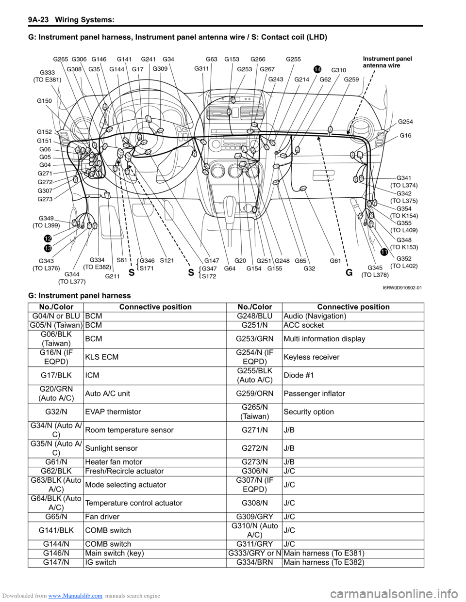
G: Instrument panel harness, Instrument panel antenna wire / S: Contact coil (LHD)
G: Instrument panel harness
G146G141
G309
G34
G253
G266G255
G144
G241
G17G311
G153 G63
G248
G310
G61
G259G243
G267
G355
(TO L409)
1311
14
G16
G341
(TO L374)
G354
(TO K154)
G342
(TO L375)
G348
(TO K153)
G352
(TO L402)
G254
G04
G271
G272
G307
12
G211
G343
(TO L376)G349
(TO L399)
G344
(TO L377)G147G345
(TO L378)
G334
(TO E382)
G333
(TO E381)
G20
S121S61
G32 G155 G154 G64
G62G214
G65 G273
G151
G152 G150
G05 G06
G308
G306 G265
G35
G251
G347
S172
G346
S171
G S S
Instrument panel
antenna wire
I6RW0D910902-01
No./Color Connective position No./Color Connective position
G04/N or BLU BCM G248/BLU Audio (Navigation)
G05/N (Taiwan) BCM G251/N ACC socket
G06/BLK
(Taiwan)BCM G253/GRN Multi information display
G16/N (IF
EQPD)KLS ECMG254/N (IF
EQPD)Keyless receiver
G17/BLK ICMG255/BLK
(Auto A/C)Diode #1
G20/GRN
(Auto A/C)Auto A/C unit G259/ORN Passenger inflator
G32/N EVAP thermistorG265/N
(Taiwan)Security option
G34/N (Auto A/
C)Room temperature sensor G271/N J/B
G35/N (Auto A/
C)Sunlight sensor G272/N J/B
G61/N Heater fan motor G273/N J/B
G62/BLK Fresh/Recircle actuator G306/N J/C
G63/BLK (Auto
A/C)Mode selecting actuatorG307/N (IF
EQPD)J/C
G64/BLK (Auto
A/C)Temperature control actuator G308/N J/C
G65/N Fan driver G309/GRY J/C
G141/BLK COMB switchG310/N (Auto
A/C)J/C
G144/N COMB switch G311/GRY J/C
G146/N Main switch (key) G333/GRY or N Main harness (To E381)
G147/N IG switch G334/BRN Main harness (To E382)
Page 1251 of 1556
Downloaded from www.Manualslib.com manuals search engine Wiring Systems: 9A-84
38 39
"D-5""D-1"
BLK/BLU
3 AA BBG042
BLU/YEL
BLU/YEL
J/C
G307
1G265
J/C
G308
G146
1 4
Main switch
(Key switch)
DOME
G2715 15A
37ACC
G2725 15A
23
WHT/REDWHT/BLK
WHT/RED
YEL/RED
YEL/RED
YEL/BLK
YEL/BLK
1E37
2
Ambient
temperature
sensor
"B-5" Switch
840
37362726
RED/BLUBRN/YELLT GRN/BLKBRNGRY/WHTGRY/RED
Parking
brake
switchSeat
belt
switch
"C-3"
RBBY
97
RED/BLK
BB
GR
Oil
pressure
switchBrake
fluid
level
switch
Security
option
GRB
G05G0617
PNK
G04
24
GRY/RED
9G0521
LgBBGWGR
Main switch
"B-5"
Sub switch
"B-5"
Front door
switch
"D-3"Switch
Front door
switch
"D-5"
BRBR
BLK/RED
R
12
RED
BLK/BLUBLK/RED
BLK/REDBLK/REDBLK/RED
J/B
FF
Rear door
switch
"D-5"
BR
DD
J/CJ/C
L346
L347
BCM
GRY
E381
G33334
G343
L3761511
I6RW0C910956-01
Page 1338 of 1556
Downloaded from www.Manualslib.com manuals search engine 9B-19 Lighting Systems:
Headlight Bulb Replacement (Discharge
Headlight Model)
S6RW0D9206002
WARNING!
• To avoid danger of being burned, don’t
touch when the bulb is hot.
• Don’t touch glass surface of bulb, to avoid
deteriorate as the case may be unclear
when bulb light on at dirty condition.
• Be sure to read “Precautions for Discharge
Headlight Service (If Equipped)” before
starting to service work.
1) Check to ensure that lighting switch is at OFF
position.
2) Disconnect negative (–) cable at battery.
3) Remove headlight housing referring to “Headlight
Housing Removal and Installation”.
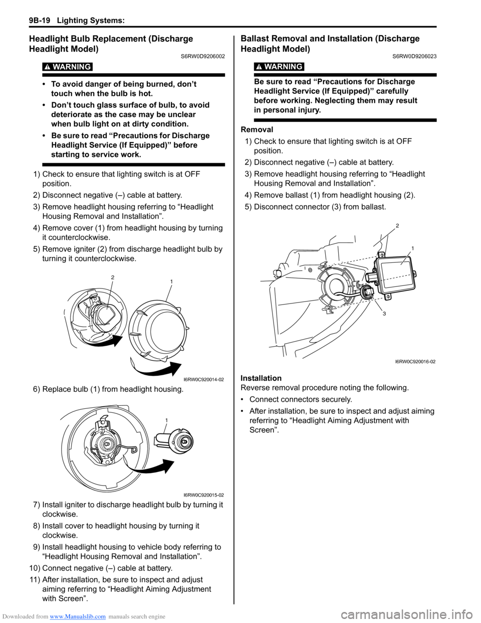
4) Remove cover (1) from headlight housing by turning
it counterclockwise.
5) Remove igniter (2) from discharge headlight bulb by
turning it counterclockwise.
6) Replace bulb (1) from headlight housing.
7) Install igniter to discharge headlight bulb by turning it
clockwise.
8) Install cover to headlight housing by turning it
clockwise.
9) Install headlight housing to vehicle body referring to
“Headlight Housing Removal and Installation”.
10) Connect negative (–) cable at battery.
11) After installation, be sure to inspect and adjust
aiming referring to “Headlight Aiming Adjustment
with Screen”.
Ballast Removal and Installation (Discharge
Headlight Model)
S6RW0D9206023
WARNING!
Be sure to read “Precautions for Discharge
Headlight Service (If Equipped)” carefully
before working. Neglecting them may result
in personal injury.
Removal
1) Check to ensure that lighting switch is at OFF
position.
2) Disconnect negative (–) cable at battery.
3) Remove headlight housing referring to “Headlight
Housing Removal and Installation”.
4) Remove ballast (1) from headlight housing (2).
5) Disconnect connector (3) from ballast.
Installation
Reverse removal procedure noting the following.
• Connect connectors securely.
• After installation, be sure to inspect and adjust aiming
referring to “Headlight Aiming Adjustment with
Screen”.
1 2
I6RW0C920014-02
1
I6RW0C920015-02
2
1
3
I6RW0C920016-02
Page 1339 of 1556
Downloaded from www.Manualslib.com manuals search engine Lighting Systems: 9B-20
Igniter Removal and Installation (Discharge
Headlight Model)
S6RW0D9206024
WARNING!
Be sure to read “Precautions for Discharge
Headlight Service (If Equipped)” carefully
before working. Neglecting them may result
in personal injury.
Removal
1) Remove ballast referring to “Ballast Removal and
Installation (Discharge Headlight Model)”.
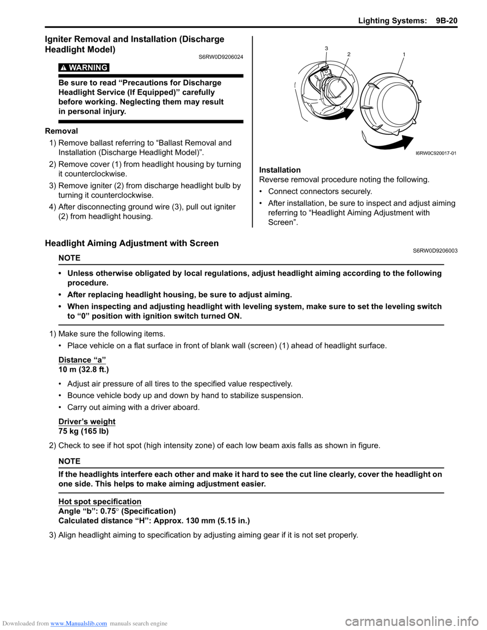
2) Remove cover (1) from headlight housing by turning
it counterclockwise.
3) Remove igniter (2) from discharge headlight bulb by
turning it counterclockwise.
4) After disconnecting ground wire (3), pull out igniter
(2) from headlight housing.Installation
Reverse removal procedure noting the following.
• Connect connectors securely.
• After installation, be sure to inspect and adjust aiming
referring to “Headlight Aiming Adjustment with
Screen”.
Headlight Aiming Adjustment with ScreenS6RW0D9206003
NOTE
• Unless otherwise obligated by local regulations, adjust headlight aiming according to the following
procedure.
• After replacing headlight housing, be sure to adjust aiming.
• When inspecting and adjusting headlight with leveling system, make sure to set the leveling switch
to “0” position with ignition switch turned ON.
1) Make sure the following items.
• Place vehicle on a flat surface in front of blank wall (screen) (1) ahead of headlight surface.
Distance “a”
10 m (32.8 ft.)
• Adjust air pressure of all tires to the specified value respectively.
• Bounce vehicle body up and down by hand to stabilize suspension.
• Carry out aiming with a driver aboard.
Driver’s weight
75 kg (165 lb)
2) Check to see if hot spot (high intensity zone) of each low beam axis falls as shown in figure.
NOTE
If the headlights interfere each other and make it hard to see the cut line clearly, cover the headlight on
one side. This helps to make aiming adjustment easier.
Hot spot specification
Angle “b”: 0.75° (Specification)
Calculated distance “H”: Approx. 130 mm (5.15 in.)
3) Align headlight aiming to specification by adjusting aiming gear if it is not set properly.
2
1 3
I6RW0C920017-01
Page 1347 of 1556
Downloaded from www.Manualslib.com manuals search engine Lighting Systems: 9B-28
Headlight Manual Levering Switch Inspection (If
Equipped)
S6RW0D9206019
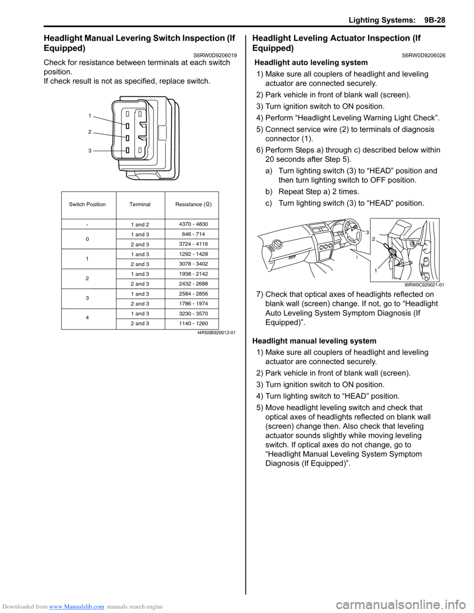
Check for resistance between terminals at each switch
position.
If check result is not as specified, replace switch.
Headlight Leveling Actuator Inspection (If
Equipped)
S6RW0D9206026
Headlight auto leveling system
1) Make sure all couplers of headlight and leveling
actuator are connected securely.
2) Park vehicle in front of blank wall (screen).
3) Turn ignition switch to ON position.
4) Perform “Headlight Leveling Warning Light Check”.
5) Connect service wire (2) to terminals of diagnosis
connector (1).
6) Perform Steps a) through c) described below within
20 seconds after Step 5).
a) Turn lighting switch (3) to “HEAD” position and
then turn lighting switch to OFF position.
b) Repeat Step a) 2 times.
c) Turn lighting switch (3) to “HEAD” position.
7) Check that optical axes of headlights reflected on
blank wall (screen) change. If not, go to “Headlight
Auto Leveling System Symptom Diagnosis (If
Equipped)”.
Headlight manual leveling system
1) Make sure all couplers of headlight and leveling
actuator are connected securely.
2) Park vehicle in front of blank wall (screen).
3) Turn ignition switch to ON position.
4) Turn lighting switch to “HEAD” position.
5) Move headlight leveling switch and check that
optical axes of headlights reflected on blank wall
(screen) change then. Also check that leveling
actuator sounds slightly while moving leveling
switch. If optical axes do not change, go to
“Headlight Manual Leveling System Symptom
Diagnosis (If Equipped)”.
1
2
3
Switch Position
0Terminal Resistance ( )
-
1
2
3
41 and 24370 - 4830
1 and 3
2 and 3
1 and 3
2 and 3
1 and 3
2 and 3
1 and 3
2 and 3
1 and 3
2 and 3646 - 714
3724 - 4116
3078 - 3402 1292 - 1428
1938 - 2142
2584 - 2856
3230 - 3570 2432 - 2688
1786 - 1974
1140 - 1260
I4RS0B920012-01
3
1
2
I6RW0C920021-01
Page 1348 of 1556
Downloaded from www.Manualslib.com manuals search engine 9B-29 Lighting Systems:
Height Sensor Removal and Installation (If
Equipped)
S6RW0D9206027
Removal
CAUTION!
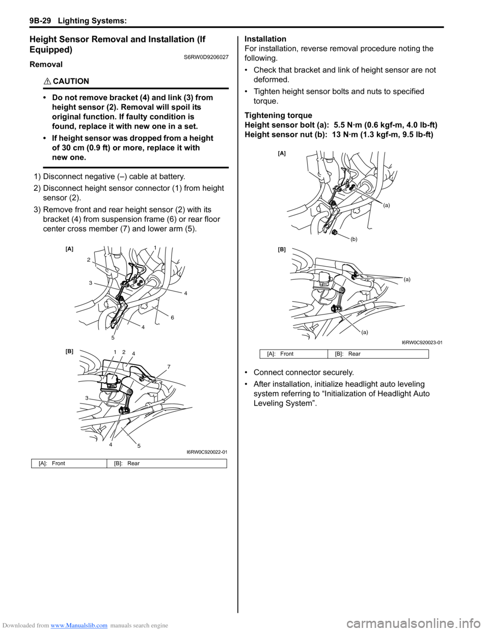
• Do not remove bracket (4) and link (3) from
height sensor (2). Removal will spoil its
original function. If faulty condition is
found, replace it with new one in a set.
• If height sensor was dropped from a height
of 30 cm (0.9 ft) or more, replace it with
new one.
1) Disconnect negative (–) cable at battery.
2) Disconnect height sensor connector (1) from height
sensor (2).
3) Remove front and rear height sensor (2) with its
bracket (4) from suspension frame (6) or rear floor
center cross member (7) and lower arm (5).Installation
For installation, reverse removal procedure noting the
following.
• Check that bracket and link of height sensor are not
deformed.
• Tighten height sensor bolts and nuts to specified
torque.
Tightening torque
Height sensor bolt (a): 5.5 N·m (0.6 kgf-m, 4.0 lb-ft)
Height sensor nut (b): 13 N·m (1.3 kgf-m, 9.5 lb-ft)
• Connect connector securely.
• After installation, initialize headlight auto leveling
system referring to “Initialization of Headlight Auto
Leveling System”.
[A]: Front [B]: Rear
12
7
[B] [A]
4
3
2
6
3
5
5
1
4
4
4
I6RW0C920022-01
[A]: Front [B]: Rear
[B] [A]
(b)
(a)
(a)
(a)
I6RW0C920023-01