Page 854 of 1556

Downloaded from www.Manualslib.com manuals search engine 5C-1 Clutch:
Transmission / Transaxle
Clutch
General Description
Clutch (Hydraulic Type) ConstructionS6RW0D5301001
The clutch is a diaphragm spring clutch of a dry single disc type. The diaphragm spring is of a tapering-finger type,
which is a solid ring in the outer diameter part, with a series of tapered fingers pointing inward.
The disc, carrying four torsional coil springs, is positioned on the transaxle input shaft with an involute spline fit.
The clutch cover is secured to the flywheel, and carries the diaphragm spring in such a way that the peripheral edge
part of the spring pushes on the pressure plate against the flywheel (with the disc in between), when the clutch release
bearing (incorporated in clutch operating cylinder) is held back. This is the engaged condition of the clutch.
Depressing the clutch pedal causes the release bearing (incorporated in clutch operating cylinder) to advance and
pushes on the tips of the tapered fingers of the diaphragm spring. When this happens, the diaphragm spring pulls the
pressure plate away from the flywheel, thereby interrupting the flow of drive from flywheel through clutch disc to
transaxle input shaft. Clutch fluid is supplied from brake fluid reservoir. Clutch fluid level can be checked by brake fluid
level of brake fluid reservoir.
I5RW0A530001-01
1. Crankshaft 4. Pressure plate 7. Operating cylinder assembly
2. Flywheel 5. Clutch cover 8. Input shaft bearing
3. Clutch disc 6. Diaphragm spring 9. Input shaft
Page 1354 of 1556

Downloaded from www.Manualslib.com manuals search engine 9C-2 Instrumentation / Driver Info. / Horn:
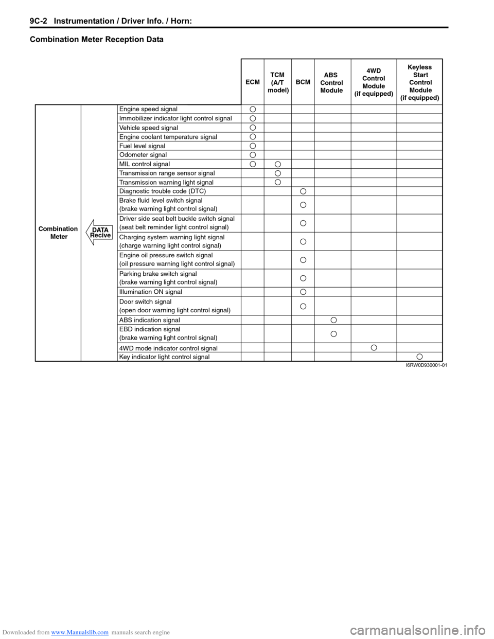
Combination Meter Reception Data
ECM BCM
Keyless
Start
Control
Module
(if equipped)
Combination
Meter4WD
Control
Module
(if equipped)TCM
(A/T
model)
Engine speed signal
Immobilizer indicator light control signal
Vehicle speed signal
Engine coolant temperature signal
Fuel level signal
MIL control signal
Transmission range sensor signal
Transmission warning light signal
Diagnostic trouble code (DTC)
Brake fluid level switch signal
(brake warning light control signal)
Driver side seat belt buckle switch signal
(seat belt reminder light control signal)
Charging system warning light signal
(charge warning light control signal)
Engine oil pressure switch signal
(oil pressure warning light control signal)
Parking brake switch signal
(brake warning light control signal)
Illumination ON signal
Door switch signal
(open door warning light control signal)
ABS indication signal
EBD indication signal
(brake warning light control signal)
4WD mode indicator control signal
Key indicator light control signal
ABS
Control
Module
Odometer signal
DATA
Recive
I6RW0D930001-01
Page 1360 of 1556

Downloaded from www.Manualslib.com manuals search engine 9C-8 Instrumentation / Driver Info. / Horn:
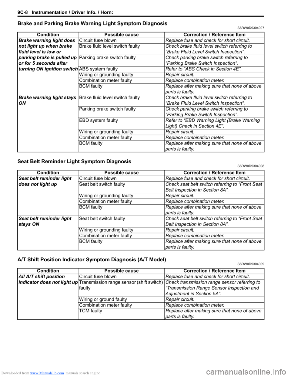
Brake and Parking Brake Warning Light Symptom DiagnosisS6RW0D9304007
Seat Belt Reminder Light Symptom DiagnosisS6RW0D9304008
A/T Shift Position Indicator Symptom Diagnosis (A/T Model)S6RW0D9304009
Condition Possible cause Correction / Reference Item
Brake warning light does
not light up when brake
fluid level is low or
parking brake is pulled up
or for 5 seconds after
turning ON ignition switchCircuit fuse blownReplace fuse and check for short circuit.
Brake fluid level switch faultyCheck brake fluid level switch referring to
“Brake Fluid Level Switch Inspection”.
Parking brake switch faultyCheck parking brake switch referring to
“Parking Brake Switch Inspection”.
ABS system faultyRefer to “ABS Check in Section 4E”.
Wiring or grounding faultyRepair circuit.
Combination meter faultyReplace combination meter.
BCM faultyReplace after making sure that none of above
parts is faulty.
Brake warning light stays
ONBrake fluid level switch faultyCheck brake fluid level switch referring to
“Brake Fluid Level Switch Inspection”.
Parking brake switch faultyCheck parking brake switch referring to
“Parking Brake Switch Inspection”.
EBD system faultyRefer to “EBD Warning Light (Brake Warning
Light) Check in Section 4E”.
Wiring or grounding faultyRepair circuit.
Combination meter faultyReplace combination meter.
BCM faultyReplace after making sure that none of above
parts is faulty.
Condition Possible cause Correction / Reference Item
Seat belt reminder light
does not light upCircuit fuse blownReplace fuse and check for short circuit.
Seat belt switch faultyCheck seat belt switch referring to “Front Seat
Belt Inspection in Section 8A”.
Wiring or grounding faultyRepair circuit.
Combination meter faultyReplace combination meter.
BCM faultyReplace after making sure that none of above
parts is faulty.
Seat belt reminder light
stays ONSeat belt switch faultyCheck seat belt switch referring to “Front Seat
Belt Inspection in Section 8A”.
Wiring or grounding faultyRepair circuit.
Combination meter faultyReplace combination meter.
BCM faultyReplace after making sure that none of above
parts is faulty.
Condition Possible cause Correction / Reference Item
All A/T shift position
indicator does not light upCircuit fuse blownReplace fuse and check for short circuit.
Transmission range sensor (shift switch)
faultyCheck transmission range sensor referring to
“Transmission Range Sensor Inspection and
Adjustment in Section 5A”.
Wiring or ground faultyRepair circuit.
Combination meter faultyReplace combination meter.
TCM faultyReplace after making sure that none of above
parts is faulty.
Page 1474 of 1556

Downloaded from www.Manualslib.com manuals search engine 10B-1 Body Electrical Control System:
Control Systems
Body Electrical Control System
Precautions
Precautions in Diagnosing TroubleS6RW0DA200001
• Diagnostic information stored in BCM memory can be cleared as well as checked by using SUZUKI scan tool.
Before using scan tool, read its Operator’s (Instruction) Manual carefully to have good understanding as to what
functions are available and how to use it.
• Be sure to read “Precautions for Electrical Circuit Service in Section 00” before inspection and observe what is
written there.
• Communication of ECM, TCM (A/T model), ABS control module, 4WD control module (if equipped), keyless start
control module (if equipped), combination meter and BCM is established by CAN (Controller Area Network). For
detail of CAN communication for BCM, refer to “CAN Communication System Description”. Therefore, handle CAN
communication line with care referring to “Precaution for CAN Communication System in Section 00”.
General Description
BCM General DescriptionS6RW0DA201001
The Body electrical Control Module (BCM) is
incorporated in junction block. Do not attempt removal of
BCM from junction block as it may cause contact failure.
The BCM incorporates relays and controllers which are
used for the following systems and controls them.
• Power door lock (if equipped)
• Keyless entry (if equipped)
• Door lock function of keyless start system (if
equipped)
• Rear wiper
• Combination meter
• Interior light• Warning buzzer
• Rear end door window defogger and door mirror
heater (if equipped)
• Rear end door opener (if equipped)
• Theft deterrent light
Also, the BCM has a function to cause the interior light
and open door warning light in the combination meter to
turn off when any door is left open for longer than 15
minutes to reduce wasteful battery consumption.
In addition, it is possible to check operation of actuator
which is controlled by BCM by using the output test
function of SUZUKI scan tool to operate actuator
simulatively.
CAN Communication System DescriptionS6RW0DA201002
Refer to “CAN Communication System Description in Section 1A” for CAN communication system description.
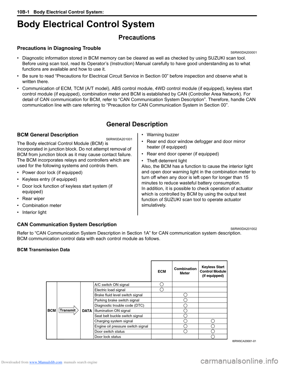
BCM communication control data with each control module as follows.
BCM Transmission Data
A/C switch ON signal
Electric load signal
Brake fluid level switch signal
Parking brake switch signal
Diagnostic trouble code (DTC)
Illumination ON signal
Seat belt buckle switch signal
Charging system signal
Engine oil pressure switch signal
Door switch status
Door lock statusECMKeyless Start
Control Module
(if equipped) Combination
Meter
BCMTransmit
DATA
I6RW0CA20001-01