2006 SUZUKI SX4 instrument panel
[x] Cancel search: instrument panelPage 1391 of 1556
Downloaded from www.Manualslib.com manuals search engine Glass / Windows / Mirrors: 9E-6
Windshield Removal and InstallationS6RW0D9506002
Preparation
The windshield is installed by using a special type of
adhesive (that is, one component urethane adhesive
used with primer). For the windshield replacement, it is
important to use an adhesive which provides sufficient
adhesion strength and follow the proper procedure.
CAUTION!
• Described is the glass replacement by
using 3 types of primers and 1 type of
adhesive made by YOKOHAMA (one
component urethane adhesive to be used
with primer in combination). When using
primer and adhesive made by other
manufacturers, be sure to refer to handling
instructions supplied with them.
Negligence in following such procedure or
misuse of the adhesive in any way hinders
its inherent adhesive property. Therefore,
before the work, make sure to read
carefully the instruction and description
given by the maker of the adhesive to be
used and be sure to follow the procedure
and observe each precaution throughout
the work.
• Should coated surface be scratched or
otherwise damaged, be sure to repair
damaged part, or corrosion may start from
there.
Use the specific adhesive which has the following
property.
Glass adhesive shearing strength
40 kg/cm2 (569 lb/in2) or moreAdhesive materials and tools required for removal and
installation.
• One component urethane adhesive and primers used
in combination (For one sheet of windshield).
– Adhesive (470 g (15.7 oz.))
– Primer for glass (30 g (1.0 oz.))
– Primer for body (30 g (1.0 oz.))
– Primer for molding (30 g (1.0 oz.))
• Eyeleteer
•Piano string
• Windshield knife
• Brush for primer application (2 pcs)
•Knife
• Rubber sucker grip
• Sealant gun (for filling adhesive)
• Putty spatula (for correcting adhered parts)
Removal
1) Clean both inside and outside of glass and around it.
2) Remove wiper arms and cowl top garnish.
3) Using tape, cover body surface around glass to
prevent any damage.
4) Remove rear view mirror, sun visor and front pillar
trims (right & left).
5) If necessary, remove instrument panel. Refer to
“Instrument Panel Removal and Installation in
Section 9C”.
6) If necessary, remove head lining. Refer to “Head
Lining Removal and Installation in Section 9H”.
7) Remove (or cut) windshield molding.
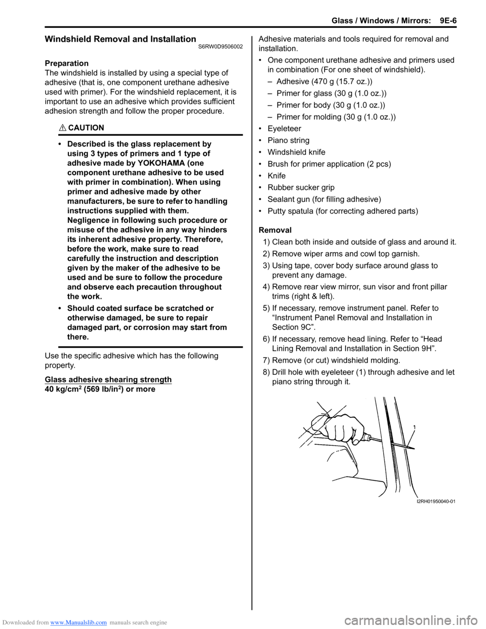
8) Drill hole with eyeleteer (1) through adhesive and let
piano string through it.
I2RH01950040-01
Page 1392 of 1556
Downloaded from www.Manualslib.com manuals search engine 9E-7 Glass / Windows / Mirrors:
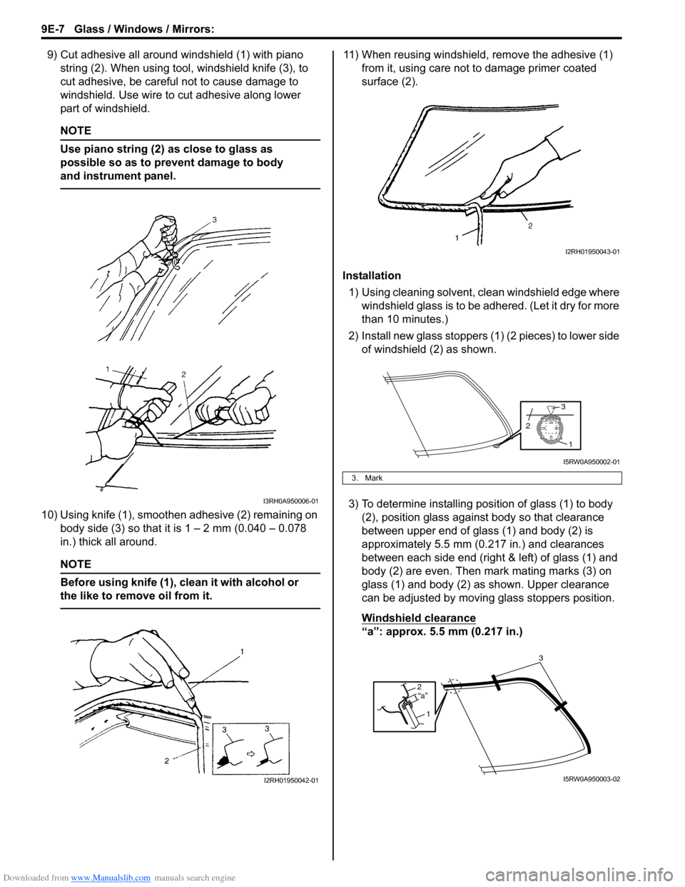
9) Cut adhesive all around windshield (1) with piano
string (2). When using tool, windshield knife (3), to
cut adhesive, be careful not to cause damage to
windshield. Use wire to cut adhesive along lower
part of windshield.
NOTE
Use piano string (2) as close to glass as
possible so as to prevent damage to body
and instrument panel.
10) Using knife (1), smoothen adhesive (2) remaining on
body side (3) so that it is 1 – 2 mm (0.040 – 0.078
in.) thick all around.
NOTE
Before using knife (1), clean it with alcohol or
the like to remove oil from it.
11) When reusing windshield, remove the adhesive (1)
from it, using care not to damage primer coated
surface (2).
Installation
1) Using cleaning solvent, clean windshield edge where
windshield glass is to be adhered. (Let it dry for more
than 10 minutes.)
2) Install new glass stoppers (1) (2 pieces) to lower side
of windshield (2) as shown.
3) To determine installing position of glass (1) to body
(2), position glass against body so that clearance
between upper end of glass (1) and body (2) is
approximately 5.5 mm (0.217 in.) and clearances
between each side end (right & left) of glass (1) and
body (2) are even. Then mark mating marks (3) on
glass (1) and body (2) as shown. Upper clearance
can be adjusted by moving glass stoppers position.
Windshield clearance
“a”: approx. 5.5 mm (0.217 in.)
I3RH0A950006-01
I2RH01950042-01
3. Mark
I2RH01950043-01
1
3
2
I5RW0A950002-01
2
1“a”
3
I5RW0A950003-02
Page 1425 of 1556
Downloaded from www.Manualslib.com manuals search engine Security and Locks: 9F-14
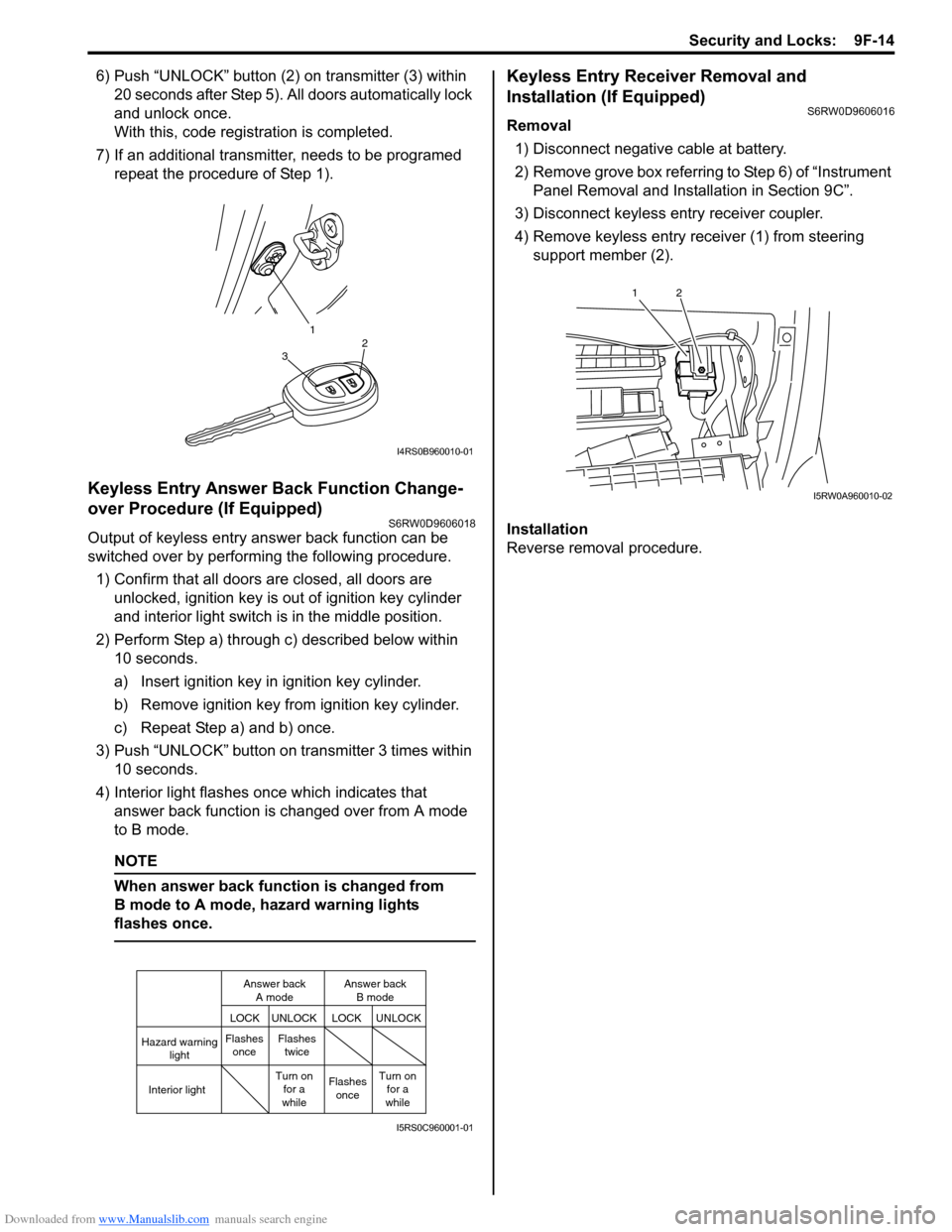
6) Push “UNLOCK” button (2) on transmitter (3) within
20 seconds after Step 5). All doors automatically lock
and unlock once.
With this, code registration is completed.
7) If an additional transmitter, needs to be programed
repeat the procedure of Step 1).
Keyless Entry Answer Back Function Change-
over Procedure (If Equipped)
S6RW0D9606018
Output of keyless entry answer back function can be
switched over by performing the following procedure.
1) Confirm that all doors are closed, all doors are
unlocked, ignition key is out of ignition key cylinder
and interior light switch is in the middle position.
2) Perform Step a) through c) described below within
10 seconds.
a) Insert ignition key in ignition key cylinder.
b) Remove ignition key from ignition key cylinder.
c) Repeat Step a) and b) once.
3) Push “UNLOCK” button on transmitter 3 times within
10 seconds.
4) Interior light flashes once which indicates that
answer back function is changed over from A mode
to B mode.
NOTE
When answer back function is changed from
B mode to A mode, hazard warning lights
flashes once.
Keyless Entry Receiver Removal and
Installation (If Equipped)
S6RW0D9606016
Removal
1) Disconnect negative cable at battery.
2) Remove grove box referring to Step 6) of “Instrument
Panel Removal and Installation in Section 9C”.
3) Disconnect keyless entry receiver coupler.
4) Remove keyless entry receiver (1) from steering
support member (2).
Installation
Reverse removal procedure.
1
32
I4RS0B960010-01
Hazard warning
light
LOCK LOCKUNLOCK UNLOCK
Interior lightFlashes
onceFlashes
twice
Flashes
once Turn on
for a
whileTurn on
for a
while Answer back
A modeAnswer back
B mode
I5RS0C960001-01
12
I5RW0A960010-02
Page 1449 of 1556
Downloaded from www.Manualslib.com manuals search engine Body Structure: 9K-5
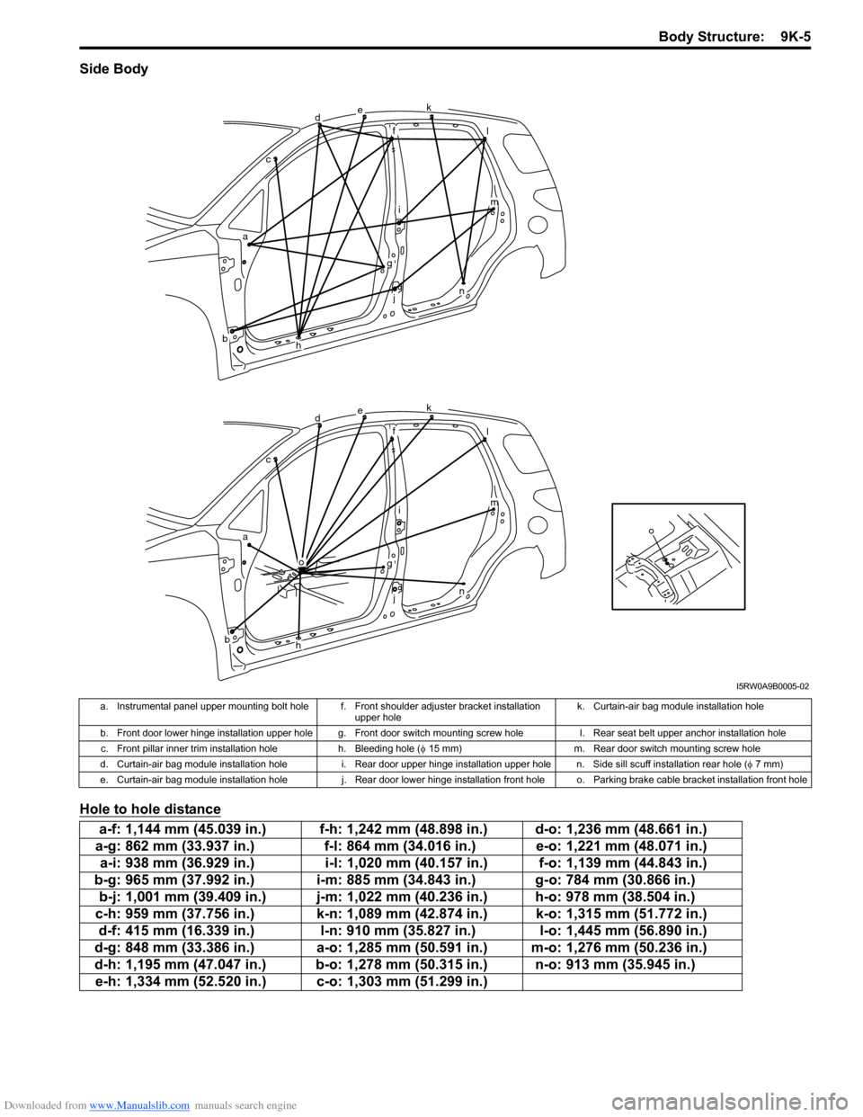
Side Body
Hole to hole distance
o
dek
fl
im
n
g
j
h
o
ac
b
dek
fl
im
n
g
j
h
ac
b
I5RW0A9B0005-02
a. Instrumental panel upper mounting bolt hole f. Front shoulder adjuster bracket installation
upper holek. Curtain-air bag module installation hole
b. Front door lower hinge installation upper hole g. Front door switch mounting screw hole l. Rear seat belt upper anchor installation hole
c. Front pillar inner trim installation hole h. Bleeding hole (φ 15 mm) m. Rear door switch mounting screw hole
d. Curtain-air bag module installation hole i. Rear door upper hinge installation upper hole n. Side sill scuff installation rear hole (φ 7 mm)
e. Curtain-air bag module installation hole j. Rear door lower hinge installation front hole o. Parking brake cable bracket installation front hole
a-f: 1,144 mm (45.039 in.) f-h: 1,242 mm (48.898 in.) d-o: 1,236 mm (48.661 in.)
a-g: 862 mm (33.937 in.) f-l: 864 mm (34.016 in.) e-o: 1,221 mm (48.071 in.)
a-i: 938 mm (36.929 in.) i-l: 1,020 mm (40.157 in.) f-o: 1,139 mm (44.843 in.)
b-g: 965 mm (37.992 in.) i-m: 885 mm (34.843 in.) g-o: 784 mm (30.866 in.)
b-j: 1,001 mm (39.409 in.) j-m: 1,022 mm (40.236 in.) h-o: 978 mm (38.504 in.)
c-h: 959 mm (37.756 in.) k-n: 1,089 mm (42.874 in.) k-o: 1,315 mm (51.772 in.)
d-f: 415 mm (16.339 in.) l-n: 910 mm (35.827 in.) l-o: 1,445 mm (56.890 in.)
d-g: 848 mm (33.386 in.) a-o: 1,285 mm (50.591 in.) m-o: 1,276 mm (50.236 in.)
d-h: 1,195 mm (47.047 in.) b-o: 1,278 mm (50.315 in.) n-o: 913 mm (35.945 in.)
e-h: 1,334 mm (52.520 in.) c-o: 1,303 mm (51.299 in.)
Page 1471 of 1556
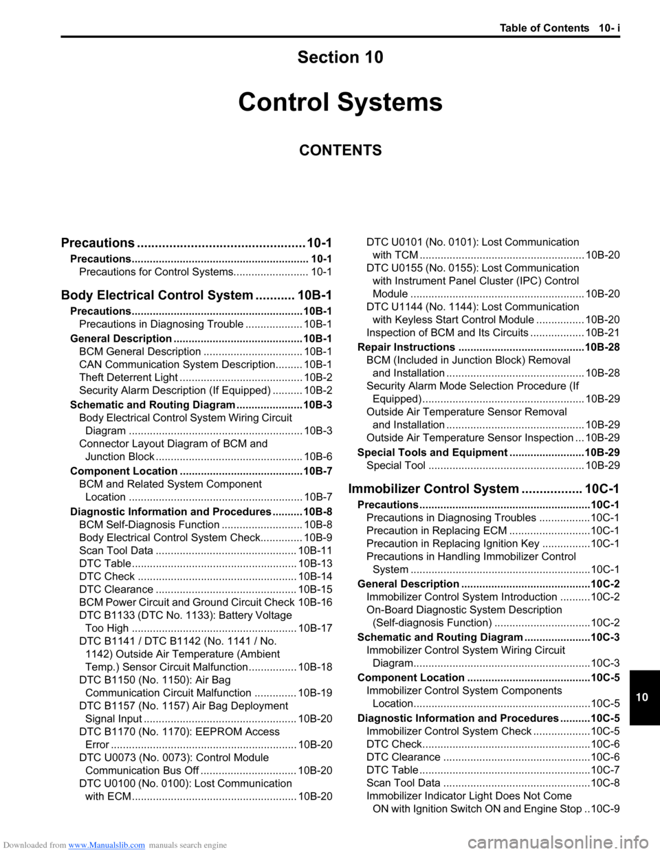
Downloaded from www.Manualslib.com manuals search engine Table of Contents 10- i
10
Section 10
CONTENTS
Control Systems
Precautions ............................................... 10-1
Precautions........................................................... 10-1
Precautions for Control Systems......................... 10-1
Body Electrical Control System ........... 10B-1
Precautions......................................................... 10B-1
Precautions in Diagnosing Trouble ................... 10B-1
General Description ........................................... 10B-1
BCM General Description ................................. 10B-1
CAN Communication System Description......... 10B-1
Theft Deterrent Light ......................................... 10B-2
Security Alarm Description (If Equipped) .......... 10B-2
Schematic and Routing Diagram ...................... 10B-3
Body Electrical Control System Wiring Circuit
Diagram .......................................................... 10B-3
Connector Layout Diagram of BCM and
Junction Block ................................................. 10B-6
Component Location ......................................... 10B-7
BCM and Related System Component
Location .......................................................... 10B-7
Diagnostic Information and Procedures .......... 10B-8
BCM Self-Diagnosis Function ........................... 10B-8
Body Electrical Control System Check.............. 10B-9
Scan Tool Data ............................................... 10B-11
DTC Table ....................................................... 10B-13
DTC Check ..................................................... 10B-14
DTC Clearance ............................................... 10B-15
BCM Power Circuit and Ground Circuit Check 10B-16
DTC B1133 (DTC No. 1133): Battery Voltage
Too High ....................................................... 10B-17
DTC B1141 / DTC B1142 (No. 1141 / No.
1142) Outside Air Temperature (Ambient
Temp.) Sensor Circuit Malfunction ................ 10B-18
DTC B1150 (No. 1150): Air Bag
Communication Circuit Malfunction .............. 10B-19
DTC B1157 (No. 1157) Air Bag Deployment
Signal Input ................................................... 10B-20
DTC B1170 (No. 1170): EEPROM Access
Error .............................................................. 10B-20
DTC U0073 (No. 0073): Control Module
Communication Bus Off ................................ 10B-20
DTC U0100 (No. 0100): Lost Communication
with ECM....................................................... 10B-20DTC U0101 (No. 0101): Lost Communication
with TCM ....................................................... 10B-20
DTC U0155 (No. 0155): Lost Communication
with Instrument Panel Cluster (IPC) Control
Module .......................................................... 10B-20
DTC U1144 (No. 1144): Lost Communication
with Keyless Start Control Module ................ 10B-20
Inspection of BCM and Its Circuits .................. 10B-21
Repair Instructions ..........................................10B-28
BCM (Included in Junction Block) Removal
and Installation .............................................. 10B-28
Security Alarm Mode Selection Procedure (If
Equipped) ...................................................... 10B-29
Outside Air Temperature Sensor Removal
and Installation .............................................. 10B-29
Outside Air Temperature Sensor Inspection ... 10B-29
Special Tools and Equipment .........................10B-29
Special Tool .................................................... 10B-29
Immobilizer Control System ................. 10C-1
Precautions.........................................................10C-1
Precautions in Diagnosing Troubles .................10C-1
Precaution in Replacing ECM ...........................10C-1
Precaution in Replacing Ignition Key ................10C-1
Precautions in Handling Immobilizer Control
System ............................................................10C-1
General Description ...........................................10C-2
Immobilizer Control System Introduction ..........10C-2
On-Board Diagnostic System Description
(Self-diagnosis Function)................................10C-2
Schematic and Routing Diagram ......................10C-3
Immobilizer Control System Wiring Circuit
Diagram...........................................................10C-3
Component Location .........................................10C-5
Immobilizer Control System Components
Location...........................................................10C-5
Diagnostic Information and Procedures ..........10C-5
Immobilizer Control System Check ...................10C-5
DTC Check........................................................10C-6
DTC Clearance .................................................10C-6
DTC Table .........................................................10C-7
Scan Tool Data .................................................10C-8
Immobilizer Indicator Light Does Not Come
ON with Ignition Switch ON and Engine Stop ..10C-9
Page 1486 of 1556
Downloaded from www.Manualslib.com manuals search engine 10B-13 Body Electrical Control System:
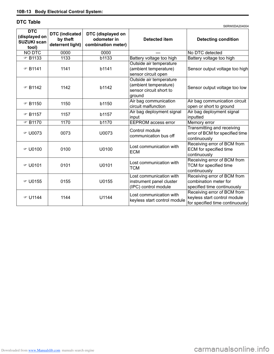
DTC TableS6RW0DA204004
DTC
(displayed on
SUZUKI scan
tool)DTC (indicated
by theft
deterrent light) DTC (displayed on
odometer in
combination meter) Detected item Detecting condition
NO DTC 0000 0000 — No DTC detected
�) B1133 1133 b1133 Battery voltage too high Battery voltage too high
�) B1141 1141 b1141Outside air temperature
(ambient temperature)
sensor circuit openSensor output voltage too high
�) B1142 1142 b1142Outside air temperature
(ambient temperature)
sensor circuit short to
groundSensor output voltage too low
�) B1150 1150 b1150Air bag communication
circuit malfunctionAir bag communication circuit
open or short to ground
�) B1157 1157 b1157Air bag deployment signal
inputAir bag deployment signal
inputted
�) B1170 1170 b1170 EEPROM access error Memory error
�) U0073 0073 U0073Control module
communication bus offTransmitting and receiving
error of BCM for specified time
continuously
�) U0100 0100 U0100Lost communication with
ECMReceiving error of BCM from
ECM for specified time
continuously
�) U0101 0101 U0101Lost communication with
TCMReceiving error of BCM from
TCM for specified time
continuously
�) U0155 0155 U0155Lost communication with
instrument panel cluster
(IPC) control moduleReceiving error of BCM from
combination meter for
specified time continuously
�) U1144 1144 U1144Lost communication with
keyless start control moduleReceiving error of BCM from
keyless start control module
for specified time continuously
Page 1487 of 1556
Downloaded from www.Manualslib.com manuals search engine Body Electrical Control System: 10B-14
DTC CheckS6RW0DA204005
Using SUZUKI Scan Tool
1) Prepare SUZUKI scan tool.
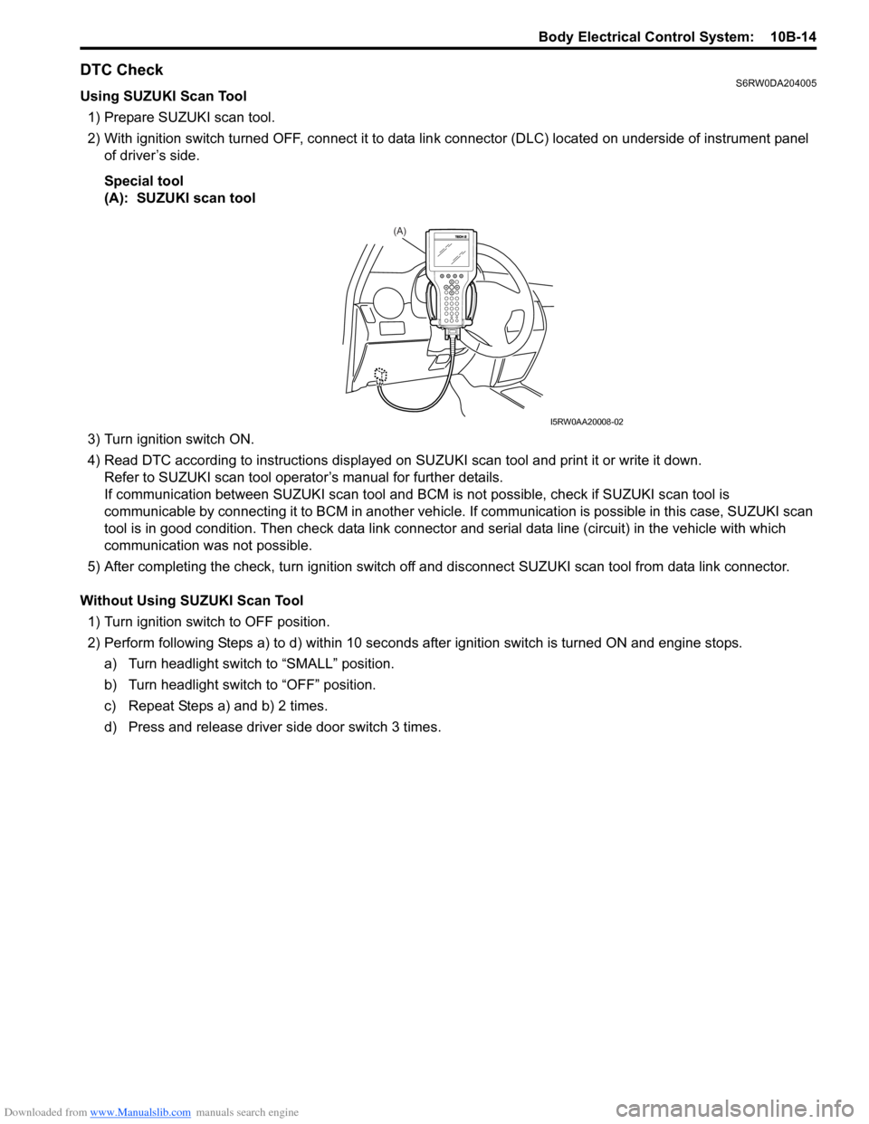
2) With ignition switch turned OFF, connect it to data link connector (DLC) located on underside of instrument panel
of driver’s side.
Special tool
(A): SUZUKI scan tool
3) Turn ignition switch ON.
4) Read DTC according to instructions displayed on SUZUKI scan tool and print it or write it down.
Refer to SUZUKI scan tool operator’s manual for further details.
If communication between SUZUKI scan tool and BCM is not possible, check if SUZUKI scan tool is
communicable by connecting it to BCM in another vehicle. If communication is possible in this case, SUZUKI scan
tool is in good condition. Then check data link connector and serial data line (circuit) in the vehicle with which
communication was not possible.
5) After completing the check, turn ignition switch off and disconnect SUZUKI scan tool from data link connector.
Without Using SUZUKI Scan Tool
1) Turn ignition switch to OFF position.
2) Perform following Steps a) to d) within 10 seconds after ignition switch is turned ON and engine stops.
a) Turn headlight switch to “SMALL” position.
b) Turn headlight switch to “OFF” position.
c) Repeat Steps a) and b) 2 times.
d) Press and release driver side door switch 3 times.
(A)
I5RW0AA20008-02
Page 1493 of 1556
Downloaded from www.Manualslib.com manuals search engine Body Electrical Control System: 10B-20
DTC B1157 (No. 1157) Air Bag Deployment Signal InputS6RW0DA204011
Wiring Diagram
Refer to “DTC B1150 (No. 1150): Air Bag Communication Circuit Malfunction”.
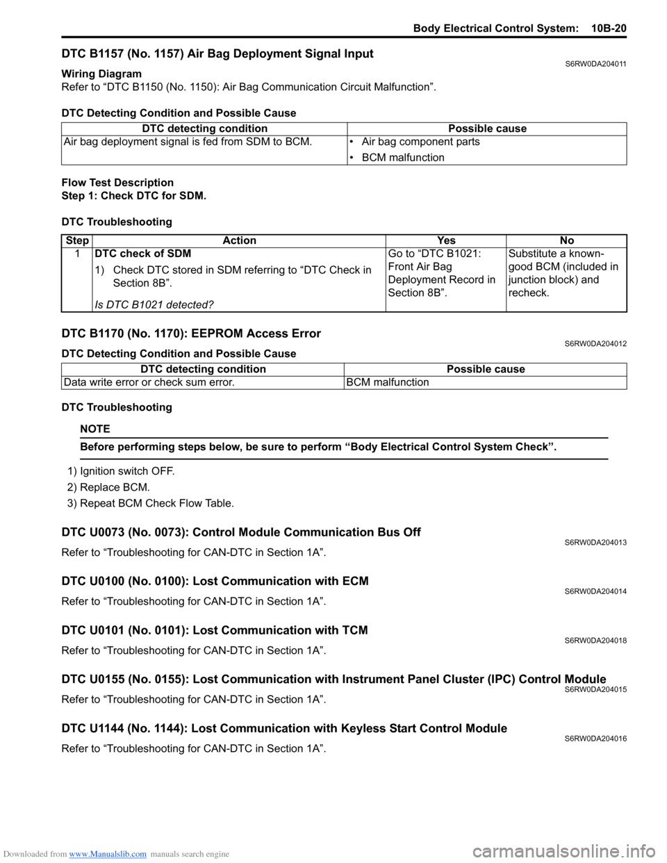
DTC Detecting Condition and Possible Cause
Flow Test Description
Step 1: Check DTC for SDM.
DTC Troubleshooting
DTC B1170 (No. 1170): EEPROM Access ErrorS6RW0DA204012
DTC Detecting Condition and Possible Cause
DTC Troubleshooting
NOTE
Before performing steps below, be sure to perform “Body Electrical Control System Check”.
1) Ignition switch OFF.
2) Replace BCM.
3) Repeat BCM Check Flow Table.
DTC U0073 (No. 0073): Control Module Communication Bus OffS6RW0DA204013
Refer to “Troubleshooting for CAN-DTC in Section 1A”.
DTC U0100 (No. 0100): Lost Communication with ECMS6RW0DA204014
Refer to “Troubleshooting for CAN-DTC in Section 1A”.
DTC U0101 (No. 0101): Lost Communication with TCMS6RW0DA204018
Refer to “Troubleshooting for CAN-DTC in Section 1A”.
DTC U0155 (No. 0155): Lost Communication with Instrument Panel Cluster (IPC) Control ModuleS6RW0DA204015
Refer to “Troubleshooting for CAN-DTC in Section 1A”.
DTC U1144 (No. 1144): Lost Communication with Keyless Start Control ModuleS6RW0DA204016
Refer to “Troubleshooting for CAN-DTC in Section 1A”. DTC detecting condition Possible cause
Air bag deployment signal is fed from SDM to BCM. • Air bag component parts
• BCM malfunction
Step Action Yes No
1DTC check of SDM
1) Check DTC stored in SDM referring to “DTC Check in
Section 8B”.
Is DTC B1021 detected?Go to “DTC B1021:
Front Air Bag
Deployment Record in
Section 8B”.Substitute a known-
good BCM (included in
junction block) and
recheck.
DTC detecting condition Possible cause
Data write error or check sum error. BCM malfunction