2006 SUZUKI SWIFT ECM power & ground circuit check
[x] Cancel search: ECM power & ground circuit checkPage 626 of 1496
Downloaded from www.Manualslib.com manuals search engine 4F-52 Electronic Stability Program:
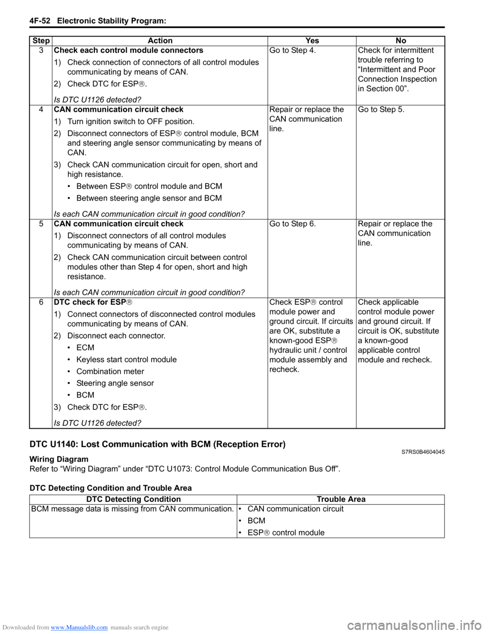
DTC U1140: Lost Communication with BCM (Reception Error)S7RS0B4604045
Wiring Diagram
Refer to “Wiring Diagram” under “DTC U1073: Control Module Communication Bus Off”.
DTC Detecting Condition and Trouble Area3
Check each control module connectors
1) Check connection of connectors of all control modules
communicating by means of CAN.
2) Check DTC for ESP ®.
Is DTC U1126 detected? Go to Step 4. Check for intermittent
trouble referring to
“Intermittent and Poor
Connection Inspection
in Section 00”.
4 CAN communication circuit check
1) Turn ignition switch to OFF position.
2) Disconnect connectors of ESP ® control module, BCM
and steering angle sensor communicating by means of
CAN.
3) Check CAN communication circuit for open, short and high resistance.
• Between ESP ® control module and BCM
• Between steering angle sensor and BCM
Is each CAN communication circuit in good condition? Repair or replace the
CAN communication
line.
Go to Step 5.
5 CAN communication circuit check
1) Disconnect connectors of all control modules
communicating by means of CAN.
2) Check CAN communication circuit between control modules other than Step 4 for open, short and high
resistance.
Is each CAN communication circuit in good condition? Go to Step 6. Repair or replace the
CAN communication
line.
6 DTC check for ESP®
1) Connect connectors of disconnected control modules
communicating by means of CAN.
2) Disconnect each connector. •ECM
• Keyless start control module
• Combination meter
• Steering angle sensor
•BCM
3) Check DTC for ESP ®.
Is DTC U1126 detected? Check ESP
® control
module power and
ground circuit. If circuits
are OK, substitute a
known-good ESP ®
hydraulic unit / control
module assembly and
recheck. Check applicable
control module power
and ground circuit. If
circuit is OK, substitute
a known-good
applicable control
module and recheck.
Step Action Yes No
DTC Detecting Condition
Trouble Area
BCM message data is missing from CAN communication. • CAN communication circuit
•BCM
• ESP® control module
Page 627 of 1496
Downloaded from www.Manualslib.com manuals search engine Electronic Stability Program: 4F-53
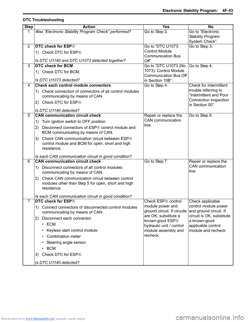
DTC TroubleshootingStep Action Yes No 1 Was “Electronic Stability Pr ogram Check” performed? Go to Step 2. Go to “Electronic
Stability Program
System Check”.
2 DTC check for ESP®
1) Check DTC for ESP ®.
Is DTC U1140 and DTC U1073 detected together? Go to “DTC U1073:
Control Module
Communication Bus
Off”.Go to Step 3.
3 DTC check for BCM
1) Check DTC for BCM.
Is DTC U1073 detected? Go to “DTC U1073 (No.
1073): Control Module
Communication Bus Off
in Section 10B”.Go to Step 4.
4 Check each control module connectors
1) Check connection of connectors of all control modules
communicating by means of CAN.
2) Check DTC for ESP ®.
Is DTC U1140 detected? Go to Step 4. Check for intermittent
trouble referring to
“Intermittent and Poor
Connection Inspection
in Section 00”.
5 CAN communication circuit check
1) Turn ignition switch to OFF position.
2) Disconnect connectors of ESP ® control module and
BCM communicating by means of CAN.
3) Check CAN communication circuit between ESP®
control module and BCM for open, short and high
resistance.
Is each CAN communication circuit in good condition? Repair or replace the
CAN communication
line.
Go to Step 6.
6 CAN communication circuit check
1) Disconnect connectors of all control modules
communicating by means of CAN.
2) Check CAN communication circuit between control modules other than Step 5 for open, short and high
resistance.
Is each CAN communication circuit in good condition? Go to Step 7. Repair or replace the
CAN communication
line.
7 DTC check for ESP®
1) Connect connectors of disconnected control modules
communicating by means of CAN.
2) Disconnect each connector. •ECM
• Keyless start control module
• Combination meter
• Steering angle sensor
•BCM
3) Check DTC for ESP ®.
Is DTC U1140 detected? Check ESP
® control
module power and
ground circuit. If circuits
are OK, substitute a
known-good ESP ®
hydraulic unit / control
module assembly and
recheck. Check applicable
control module power
and ground circuit. If
circuit is OK, substitute
a known-good
applicable control
module and recheck.
Page 687 of 1496

Downloaded from www.Manualslib.com manuals search engine Automatic Transmission/Transaxle: 5A-43
Transmission Warning Light Circuit Check – Light Does Not Come “ON” at Ignition Switch ONS7RS0B5104021
Troubleshooting
Transmission Warning Light Circuit Check – Light Remains “ON” at Ignition Switch ONS7RS0B5104022
TroubleshootingStep Action Yes No
1 Was “A/T System Check” performed? Go to Step 2. Go to “A/T System
Check”.
2 Check DTC
Is DTC P0705, P0707, P0712, P0713, P0717, P0722,
P0787, P0788, P0961, P0962, P0963, P0973, P0974,
P0976, P0977, P1702, P1703, P1774, P1777, P2762,
P2763 and/or P2764 detected? Go to applicable DTC
diag. flow.
Go to Step 3.
3 Brake light switch signal inspection
1) With ignition switch turned ON, check voltage between
terminal “C35-20” of ECM connector and ground.
Brake light switch signal specification
Brake pedal is released: 0 – 1 V
Brake pedal is depressed: 8 – 14 V
Is result as specified? Substitute a known-
good TCM and recheck.
Mis-adjusted brake light
switch or faulty brake
light switch.
Step
Action YesNo
1 Combination meter power supply check
1) Turn ignition switch ON.
Does other indicator / warnin g lights in combination meter
comes ON? Go to Step 2.
Repair combination
meter power supply
circuit referring to “C-1
Combination Meter
Circuit Diagram (Meter)
in Section 9A”.
2 TCM power and ground circuit check
1) Check referring to “TCM Power and Ground Circuit
Check”.
Is it in good condition? Go to Step 3.
Repair or replace.
3 DTC check
1) Check DTC referring to “DTC Check”.
Is there DTC P1774? Go to applicable DTC
diag. flow.
Go to Step 4.
4 Combination meter function check
1) Turn ignition switch ON.
Does A/T selector position in dicator show correct select
lever position? Replace combination
meter.
Substitute a known-
good TCM and recheck.
Step
Action YesNo
1 Diagnostic Trouble Code (DTC) Check
1) Check DTC referring to “DTC Check”.
Is there any DTC(s)? Perform DTC Flow to
repair and retry.
Substitute a known-
good TCM and recheck.
If OK, substitute a
known-good
combination meter and
recheck.
Page 688 of 1496

Downloaded from www.Manualslib.com manuals search engine 5A-44 Automatic Transmission/Transaxle:
DTC P0602: Control Module Programming ErrorS7RS0B5104048
System Description
Internal control module is installed in ECM.
DTC Detecting Condition and Trouble Area
DTC Confirmation Procedure 1) Connect scan tool to DLC with ignition switch turned OFF.
2) Clear DTC, pending DTC and freeze frame data by using scan tool.
3) Start engine and run it at idle if possible.
4) Check DTC.
DTC Troubleshooting
DTC P0705: Transmission Range Sensor Circuit Malfunction (PRNDL input)S7RS0B5104023
Wiring DiagramDTC detecting condition Trouble area
Data programming error (1 driving cycle detection logic) TCM
Step Action YesNo
1 DTC check
1) Clear DTC referring to “DTC Clearance”.
2) Turn ignition switch to OFF position.
3) Turn ignition switch to ON position and check DTC.
Is DTC P0602 still indicated? Go to Step 2.
Intermittent trouble.
Check for intermittent
referring to “Intermittent
and Poor Connection
Inspection in Section
00”.
2 TCM reprogramming check
Was reprogramming of TCM executed? Execute reprogramming
of TCM correctly once
again.Go to Step 3.
3 TCM power ground circuit check
1) Check TCM power supply circuit and ground circuit
referring to “TCM Power and Ground Circuit Check”.
Are check results OK? Substitute a known-
good TCM and recheck.
Repair TCM power or
ground circuit.
1. TCM
3. Backup lamp
2. Transmission range sensor [A]: Terminal arrangem ent of TCM connector (viewed from harness side)
2P
R
N
D 2 L 3
1
PNK/BLK
RED
GRN
GRN/ORN
GRN/YEL
IG11
RED/BLK
LT GRN/BLK
C35-20
C35-1
C35-8
C35-7
C35-19
C35-18
C34
20 19
87
18
1
C35
[A]
I4RS0A510010-01
Page 717 of 1496
Downloaded from www.Manualslib.com manuals search engine Automatic Transmission/Transaxle: 5A-73
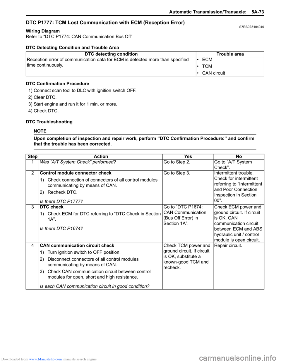
DTC P1777: TCM Lost Communication with ECM (Reception Error)S7RS0B5104040
Wiring Diagram
Refer to “DTC P1774: CAN Communication Bus Off”
DTC Detecting Condition and Trouble Area
DTC Confirmation Procedure1) Connect scan tool to DLC with ignition switch OFF.
2) Clear DTC.
3) Start engine and run it for 1 min. or more.
4) Check DTC.
DTC Troubleshooting
NOTE
Upon completion of inspection and repair work, perform “DTC Confirmation Procedure:” and confirm
that the trouble has been corrected.
DTC detecting condition Trouble area
Reception error of communication data fo r ECM is detected more than specified
time continuously. •ECM
•TCM
• CAN circuit
Step
Action YesNo
1 Was “A/T System Check” performed? Go to Step 2.Go to “A/T System
Check”.
2 Control module connector check
1) Check connection of connectors of all control modules
communicating by means of CAN.
2) Recheck DTC.
Is there DTC P1777? Go to Step 3.
Intermittent trouble.
Check for intermittent
referring to “Intermittent
and Poor Connection
Inspection in Section
00”.
3 DTC check
1) Check ECM for DTC referring to “DTC Check in Section
1A”.
Is there DTC P1674? Go to “DTC P1674:
CAN Communication
(Bus Off Error) in
Section 1A”.
Check ECM power and
ground circuit. If circuit
is OK, CAN
communication circuit
between ECM and ABS
hydraulic unit / control
module is open circuit.
4 CAN communication circuit check
1) Turn ignition switch to OFF position.
2) Disconnect connectors of all control modules
communicating by means of CAN.
3) Check CAN communication circuit between control modules for open, short and high resistance.
Is each CAN communication circuit in good condition? Check TCM power and
ground circuit. If circuit
is OK, substitute a
known-good TCM and
recheck.
Repair circuit.
Page 718 of 1496
Downloaded from www.Manualslib.com manuals search engine 5A-74 Automatic Transmission/Transaxle:
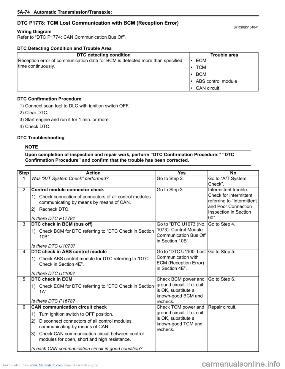
DTC P1778: TCM Lost Communication with BCM (Reception Error)S7RS0B5104041
Wiring Diagram
Refer to “DTC P1774: CAN Communication Bus Off”.
DTC Detecting Condition and Trouble Area
DTC Confirmation Procedure
1) Connect scan tool to DLC with ignition switch OFF.
2) Clear DTC.
3) Start engine and run it for 1 min. or more.
4) Check DTC.
DTC Troubleshooting
NOTE
Upon completion of inspection and repair work, perform “DTC Confirmation Procedure:” “DTC
Confirmation Procedure” and confirm that the trouble has been corrected.
DTC detecting condition Trouble area
Reception error of communication data fo r BCM is detected more than specified
time continuously. •ECM
•TCM
•BCM
• ABS control module
• CAN circuit
Step
Action YesNo
1 Was “A/T System Check” performed? Go to Step 2.Go to “A/T System
Check”.
2 Control module connector check
1) Check connection of connectors of all control modules
communicating by means by means of CAN.
2) Recheck DTC.
Is there DTC P1778? Go to Step 3.
Intermittent trouble.
Check for intermittent
referring to “Intermittent
and Poor Connection
Inspection in Section
00”.
3 DTC check in BCM (bus off)
1) Check BCM for DTC referring to “DTC Check in Section
10B”.
Is there DTC U1073? Go to “DTC U1073 (No.
1073): Control Module
Communication Bus Off
in Section 10B”.
Go to Step 4.
4 DTC check in ABS control module
1) Check ABS control module for DTC referring to “DTC
Check in Section 4E”.
Is there DTC U1100? Go to “DTC U1100: Lost
Communication with
ECM (Reception Error)
in Section 4E”.
Go to Step 5.
5 DTC check in ECM
1) Check ECM for DTC referring to “DTC Check in Section
1A”.
Is there DTC P1678? Check BCM power and
ground circuit. If circuit
is OK, substitute a
known-good BCM and
recheck.Go to Step 6.
6 CAN communication circuit check
1) Turn ignition switch to OFF position.
2) Disconnect connectors of all control modules
communicating by means of CAN.
3) Check CAN communication circuit between control modules for open, short and high resistance.
Is each CAN communication circuit in good condition? Check TCM power and
ground circuit. If circuit
is OK, substitute a
known-good TCM and
recheck.
Repair circuit.
Page 896 of 1496

Downloaded from www.Manualslib.com manuals search engine 6C-14 Power Assisted Steering System:
TroubleshootingStep Action Yes No 1 Was “EPS System Check” performed? Go to Step 2. Go to “EPS System
Check”.
2 1) Make sure that SUZUKI scan tool is free from malfunction and that correct program card (software) for
P/S system is used.
2) Turn ignition switch to OFF position.
3) Check proper connection of SUZUKI scan tool to DLC.
Is connection in good condition? Go to Step 3. Connect SUZUKI scan
tool to DLC properly.
3 1) Check if communication is possible by making communication with other controllers (ECM, BCM, ABS
or SDM) or other vehicles.
Is it possible to communic ate with the other controllers? Go to Step 4. Repair open in common
section of “serial data
circuit” (“PPL/WHT” wire
circuit) used by all
controllers or short to
ground or power circuit
which has occurred
somewhere in serial
data circuit (“PPL/WHT”
wire circuit).
4 1) Check power supply circuit and ground circuit for P/S control module referring to “P/S Control Module Power
Supply and Ground Circuit Check”.
Is check result in good condition? Go to Step 5. Repair or replace
defective circuit.
5 1) With ignition switch turned OFF, disconnect “E52” connector from P/S control module and check for
terminal to P/S control module connector.
2) If connections are OK, check t hat “Serial data circuit” is
as following.
• Insulation resistance of “Serial data circuit” wire is infinity between its terminal and other terminals at P/S
control module connector.
• Wiring resistance of “Seria l data circuit” wire is less
than 1 Ω.
• Insulation resistance of “Serial data circuit” wire is infinity between its terminal and vehicle body ground.
Is circuit in good condition? Substitute a known-
good P/S control
module and recheck.
Repair or replace
defective circuit.
Page 909 of 1496
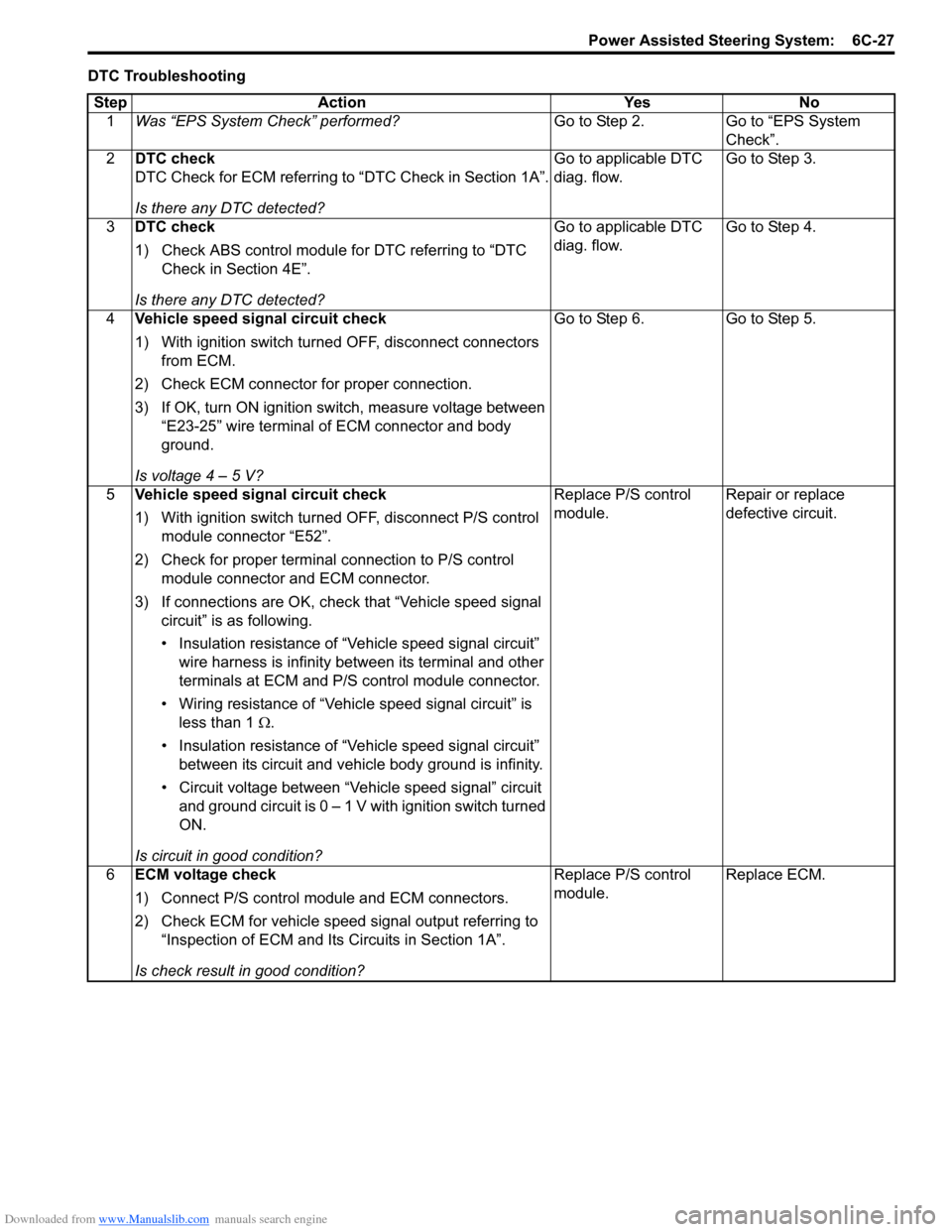
Downloaded from www.Manualslib.com manuals search engine Power Assisted Steering System: 6C-27
DTC TroubleshootingStep Action Yes No 1 Was “EPS System Check” performed? Go to Step 2. Go to “EPS System
Check”.
2 DTC check
DTC Check for ECM referring to “DTC Check in Section 1A”.
Is there any DTC detected? Go to applicable DTC
diag. flow.
Go to Step 3.
3 DTC check
1) Check ABS control module for DTC referring to “DTC
Check in Section 4E”.
Is there any DTC detected? Go to applicable DTC
diag. flow.
Go to Step 4.
4 Vehicle speed signal circuit check
1) With ignition switch turned OFF, disconnect connectors
from ECM.
2) Check ECM connector for proper connection.
3) If OK, turn ON ignition switch, measure voltage between “E23-25” wire terminal of ECM connector and body
ground.
Is voltage 4 – 5 V? Go to Step 6.
Go to Step 5.
5 Vehicle speed signal circuit check
1) With ignition switch turned OFF, disconnect P/S control
module connector “E52”.
2) Check for proper terminal connection to P/S control module connector and ECM connector.
3) If connections are OK, chec k that “Vehicle speed signal
circuit” is as following.
• Insulation resistance of “Vehicle speed signal circuit” wire harness is infinity between its terminal and other
terminals at ECM and P/S control module connector.
• Wiring resistance of “Vehicle speed signal circuit” is less than 1 Ω.
• Insulation resistance of “Vehicle speed signal circuit” between its circuit and vehicle body ground is infinity.
• Circuit voltage between “Vehicle speed signal” circuit and ground circuit is 0 – 1 V with ignition switch turned
ON.
Is circuit in good condition? Replace P/S control
module.
Repair or replace
defective circuit.
6 ECM voltage check
1) Connect P/S control mo dule and ECM connectors.
2) Check ECM for vehicle speed signal output referring to “Inspection of ECM and Its Circuits in Section 1A”.
Is check result in good condition? Replace P/S control
module.
Replace ECM.