2006 SUZUKI SWIFT Codes bcm
[x] Cancel search: Codes bcmPage 1048 of 1496
Downloaded from www.Manualslib.com manuals search engine 8B-10 Air Bag System:
Diagnostic Information and Procedures
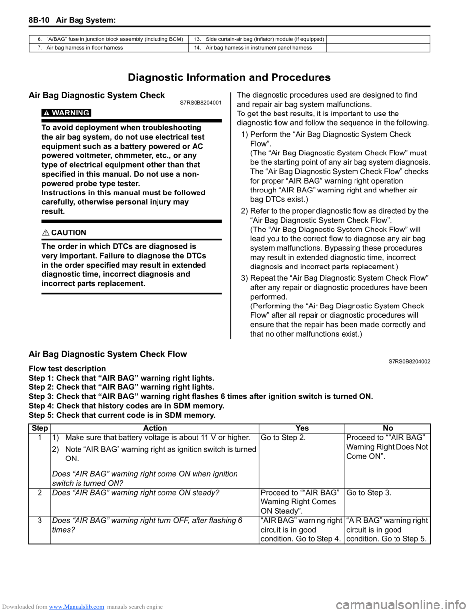
Air Bag Diagnostic System CheckS7RS0B8204001
WARNING!
To avoid deployment when troubleshooting
the air bag system, do not use electrical test
equipment such as a battery powered or AC
powered voltmeter, ohmmeter, etc., or any
type of electrical equipment other than that
specified in this manual. Do not use a non-
powered probe type tester.
Instructions in this manual must be followed
carefully, otherwise personal injury may
result.
CAUTION!
The order in which DTCs are diagnosed is
very important. Failure to diagnose the DTCs
in the order specified may result in extended
diagnostic time, incorrect diagnosis and
incorrect parts replacement.
The diagnostic procedures used are designed to find
and repair air bag system malfunctions.
To get the best results, it is important to use the
diagnostic flow and follow the sequence in the following.1) Perform the “Air Bag Diagnostic System Check Flow”.
(The “Air Bag Diagnostic System Check Flow” must
be the starting point of any air bag system diagnosis.
The “Air Bag Diagnostic System Check Flow” checks
for proper “AIR BAG” warning right operation
through “AIR BAG” warning right and whether air
bag DTCs exist.)
2) Refer to the proper diagnost ic flow as directed by the
“Air Bag Diagnostic System Check Flow”.
(The “Air Bag Diagnostic System Check Flow” will
lead you to the correct flow to diagnose any air bag
system malfunctions. Bypassing these procedures
may result in extended diagnostic time, incorrect
diagnosis and incorrect parts replacement.)
3) Repeat the “Air Bag Diagnostic System Check Flow” after any repair or diagnostic procedures have been
performed.
(Performing the “Air Bag Diagnostic System Check
Flow” after all repair or diagnostic procedures will
ensure that the repair has been made correctly and
that no other malfunctions exist.)
Air Bag Diagnostic System Check FlowS7RS0B8204002
Flow test description
Step 1: Check that “AIR BAG” warning right lights.
Step 2: Check that “AIR BAG” warning right lights.
Step 3: Check that “AIR BAG” warning right flas hes 6 times after ignition switch is turned ON.
Step 4: Check that history codes are in SDM memory.
Step 5: Check that current code is in SDM memory.
6. “A/BAG” fuse in junction block assembly (including BCM) 13. Side curtain-air bag (inflator) module (if equipped)
7. Air bag harness in floor harness 14. Air bag harness in instrument panel harness
Step Action YesNo
1 1) Make sure that battery voltage is about 11 V or higher.
2) Note “AIR BAG” warning right as ignition switch is turned
ON.
Does “AIR BAG” warning ri ght come ON when ignition
switch is turned ON? Go to Step 2.
Proceed to ““AIR BAG”
Warning Right Does Not
Come ON”.
2 Does “AIR BAG” warning right come ON steady? Proceed to ““AIR BAG”
Warning Right Comes
ON Steady”.Go to Step 3.
3 Does “AIR BAG” warning right turn OFF, after flashing 6
times? “AIR BAG” warning right
circuit is in good
condition. Go to Step 4.“AIR BAG” warning right
circuit is in good
condition. Go to Step 5.
Page 1359 of 1496
Downloaded from www.Manualslib.com manuals search engine Security and Locks: 9F-13
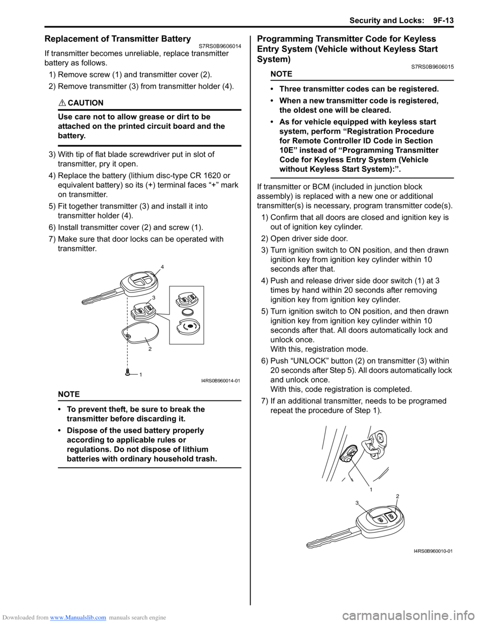
Replacement of Transmitter Battery S7RS0B9606014
If transmitter becomes unreliable, replace transmitter
battery as follows.
1) Remove screw (1) and transmitter cover (2).
2) Remove transmitter (3) from transmitter holder (4).
CAUTION!
Use care not to allow grease or dirt to be
attached on the printed circuit board and the
battery.
3) With tip of flat blade screwdriver put in slot of transmitter, pry it open.
4) Replace the battery (lithium disc-type CR 1620 or equivalent battery) so its (+) terminal faces “+” mark
on transmitter.
5) Fit together transmitter (3) and install it into
transmitter holder (4).
6) Install transmitter co ver (2) and screw (1).
7) Make sure that door locks can be operated with transmitter.
NOTE
• To prevent theft, be sure to break the transmitter before discarding it.
• Dispose of the used battery properly according to applicable rules or
regulations. Do not dispose of lithium
batteries with ordinary household trash.
Programming Transmitter Code for Keyless
Entry System (Vehicle without Keyless Start
System)
S7RS0B9606015
NOTE
• Three transmitter codes can be registered.
• When a new transmitter code is registered, the oldest one will be cleared.
• As for vehicle equipped with keyless start system, perform “Registration Procedure
for Remote Controller ID Code in Section
10E” instead of “Programming Transmitter
Code for Keyless Entry System (Vehicle
without Keyless Start System):”.
If transmitter or BCM (included in junction block
assembly) is replaced with a new one or additional
transmitter(s) is necessary, program transmitter code(s).
1) Confirm that all doors are closed and ignition key is
out of ignition key cylinder.
2) Open driver side door.
3) Turn ignition switch to ON position, and then drawn ignition key from igniti on key cylinder within 10
seconds after that.
4) Push and release driver side door switch (1) at 3 times by hand within 20 seconds after removing
ignition key from ig nition key cylinder.
5) Turn ignition switch to ON position, and then drawn ignition key from igniti on key cylinder within 10
seconds after that. All d oors automatically lock and
unlock once.
With this, registration mode.
6) Push “UNLOCK” button (2) on transmitter (3) within
20 seconds after Step 5). All doors automatically lock
and unlock once.
With this, code registration is completed.
7) If an additional transmitter, needs to be programed repeat the procedure of Step 1).
23
4
1I4RS0B960014-01
1
32
I4RS0B960010-01
Page 1402 of 1496
Downloaded from www.Manualslib.com manuals search engine 10-ii Table of Contents
DTC P1615: ID Code Does Not Registered (Vehicle equipped with keyless start system
only) ................................................................10C-9
DTC P1616: Different Registration ID Codes (Vehicle equipped with keyless start system
only) ..............................................................10C-10
DTC P1618: CAN Communication Error (Reception Error for Keyless Start Control
Module) (Vehicle equipped with keyless
start system only) ..........................................10C-11
DTC P1621: Immobilizer Communication Line Error ......................................................10C-12
DTC P1622: EEPROM Reading / Writing Error ..............................................................10C-13
DTC P1623: Unregistered Transponder .........10C-13
DTC P1625: Immobilizer An tenna Error..........10C-14
DTC P1636: Immobilizer Information Registration Failure .......................................10C-14
DTC P1638: Immobilizer Information Mismatched ...................................................10C-15
Inspection of Immobilizer Control Module (ICM) and Its Circuit ....... ...............................10C-16
Repair Instructions ........... ...............................10C-18
Immobilizer Control Mo dule (ICM) Removal
and Installation ..............................................10C-18
Registration of the Ignition Key .......................10C-18
Procedure after ECM Replacement ................10C-18
Special Tools and Equipmen t .........................10C-19
Special Tool ....................................................10C-19
Keyless Start System ....... ......................10E-1
General Description ........................................... 10E-1
Keyless Start System Description ..................... 10E-1
Parts and Functions .......................................... 10E-2
Keyless Engine Start Function .......................... 10E-3
Door Lock Function of Keyless Start System .... 10E-4
Operation Area of Remote Controller................ 10E-5
Alarm Function .................................................. 10E-6
CAN Communication System Description......... 10E-6
Schematic and Routing Diagram ...................... 10E-7 Keyless Start System El ectric Wiring Circuit
Diagram .......................................................... 10E-7
Diagnostic Information and Procedures .......... 10E-8 Precautions in Diagnosing Troubles ................. 10E-8
Self-Diagnosis Function .................................... 10E-8
Keyless Start System Diagn osis Introduction ... 10E-8 Keyless Start System Chec
k ............................. 10E-8
Customer Questionnaire (E xample) .................. 10E-9
Key Indicator Lamp Check .............................. 10E-10
DTC Check...................................................... 10E-10
DTC Table ....................................................... 10E-11
DTC Clearance ............................................... 10E-12
Keyless Start System Symp tom Diagnosis ..... 10E-12
Keyless Start System Operation Inspection .... 10E-13
Door Lock Operation (Keyless Start System) . 10E-14
Inspection of Keyless Start Control Module and Its Circuits .............................................. 10E-14
No DTC Detection After Performing DTC Check ............................................................ 10E-18
Key Indicator Lamp Circuit Check (Key indicator lamp doesn’t light when ignition
knob switch is pushed.) ................................. 10E-20
Keyless Start Control Module Power and Ground Circuit Check .................................... 10E-22
DTC No. 11: Communi cation Error with
Steering Lock Unit ......................................... 10E-23
DTC No. 13 / No. 14: Release Signal Error from Steering Lock Unit / Steering Lock Unit
Malfunction .................................................... 10E-24
DTC No. 21 / No. 22: Internal Error of Keyless Start Control Module (EEPROM reading
error) / (EEPROM writing error) ............ ........ 10E-24
DTC No. 31: Lost Commun ication with BCM .. 10E-25
DTC No. 33: Control Module Communication
Bus Off .......................................................... 10E-27
DTC No. 51 / No. 52 / No. 53: Driver Side / Passenger Side / Rear End Door Request
Switch Failure................................................ 10E-28
Repair Instructions ............ .............................. 10E-30
Antennas and Request Switches Removal and Installation .............................................. 10E-30
Front Door (Driver and Passenger Side), Rear End Door Request Switch Inspection............ 10E-31
Steering Lock Unit Removal and Installation .. 10E-31
Steering Lock Unit Inspection ......................... 10E-31
Front Door Lock Switch In spection ................. 10E-31
Keyless Start Control Module Removal and Installation ..................................................... 10E-32
Remote Controller Inspection.......................... 10E-32
Replacement of Remote Controller Battery .... 10E-32
Registration Procedure for Remote Controller
ID Code ......................................................... 10E-33
Page 1449 of 1496
Downloaded from www.Manualslib.com manuals search engine Immobilizer Control System: 10C-6
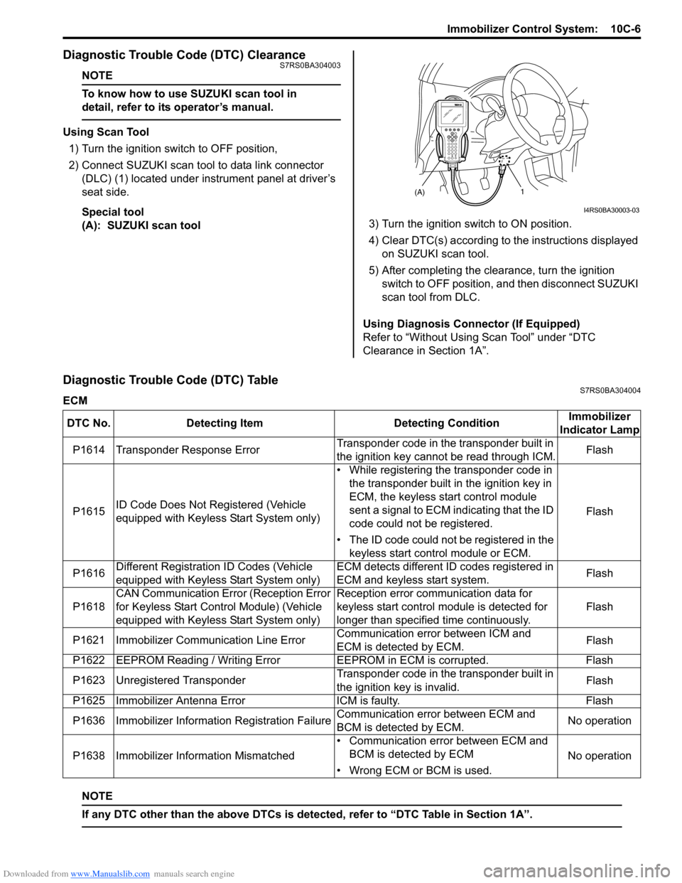
Diagnostic Trouble Code (DTC) ClearanceS7RS0BA304003
NOTE
To know how to use SUZUKI scan tool in
detail, refer to its operator’s manual.
Using Scan Tool
1) Turn the ignition switch to OFF position,
2) Connect SUZUKI scan tool to data link connector (DLC) (1) located under instrument panel at driver’s
seat side.
Special tool
(A): SUZUKI scan tool 3) Turn the ignition switch to ON position.
4) Clear DTC(s) according to the instructions displayed
on SUZUKI scan tool.
5) After completing the clearance, turn the ignition switch to OFF position, and then disconnect SUZUKI
scan tool from DLC.
Using Diagnosis Connector (If Equipped)
Refer to “Without Using Scan Tool” under “DTC
Clearance in Section 1A”.
Diagnostic Trouble Code (DTC) TableS7RS0BA304004
ECM
NOTE
If any DTC other than the above DTCs is detected, refer to “DTC Table in Section 1A”.
(A)1
I4RS0BA30003-03
DTC No. Detecting Item Detecting ConditionImmobilizer
Indicator Lamp
P1614 Transponder Response Error Transponder code in the transponder built in
the ignition key cannot be read through ICM.Flash
P1615 ID Code Does Not Re
gistered (Vehicle
equipped with Keyless Start System only) • While registering the transponder code in
the transponder built in the ignition key in
ECM, the keyless start control module
sent a signal to ECM indicating that the ID
code could not be registered.
• The ID code could not be registered in the keyless start control module or ECM. Flash
P1616 Different Registration ID Codes (Vehicle
equipped with Keyless Start System only) ECM detects different ID codes registered in
ECM and keyless start system.
Flash
P1618 CAN Communication Error (Reception Error
for Keyless Start Control Module) (Vehicle
equipped with Keyless Start System only) Reception error communication data for
keyless start control module is detected for
longer than specified time continuously.
Flash
P1621 Immobilizer Commu nication Line ErrorCommunication error between ICM and
ECM is detected by ECM. Flash
P1622 EEPROM Reading / Writing Error EEPROM in ECM is corrupted.Flash
P1623 Unregistered Transponder Transponder code in the transponder built in
the ignition key is invalid.Flash
P1625 Immobilizer Antenna Error ICM is faulty.Flash
P1636 Immobilizer Information Registration Failure Communication error between ECM and
BCM is detected by ECM.No operation
P1638 Immobilizer Info rmation Mismatched • Communication error between ECM and
BCM is detected by ECM
• Wrong ECM or BCM is used. No operation
Page 1450 of 1496
Downloaded from www.Manualslib.com manuals search engine 10C-7 Immobilizer Control System:
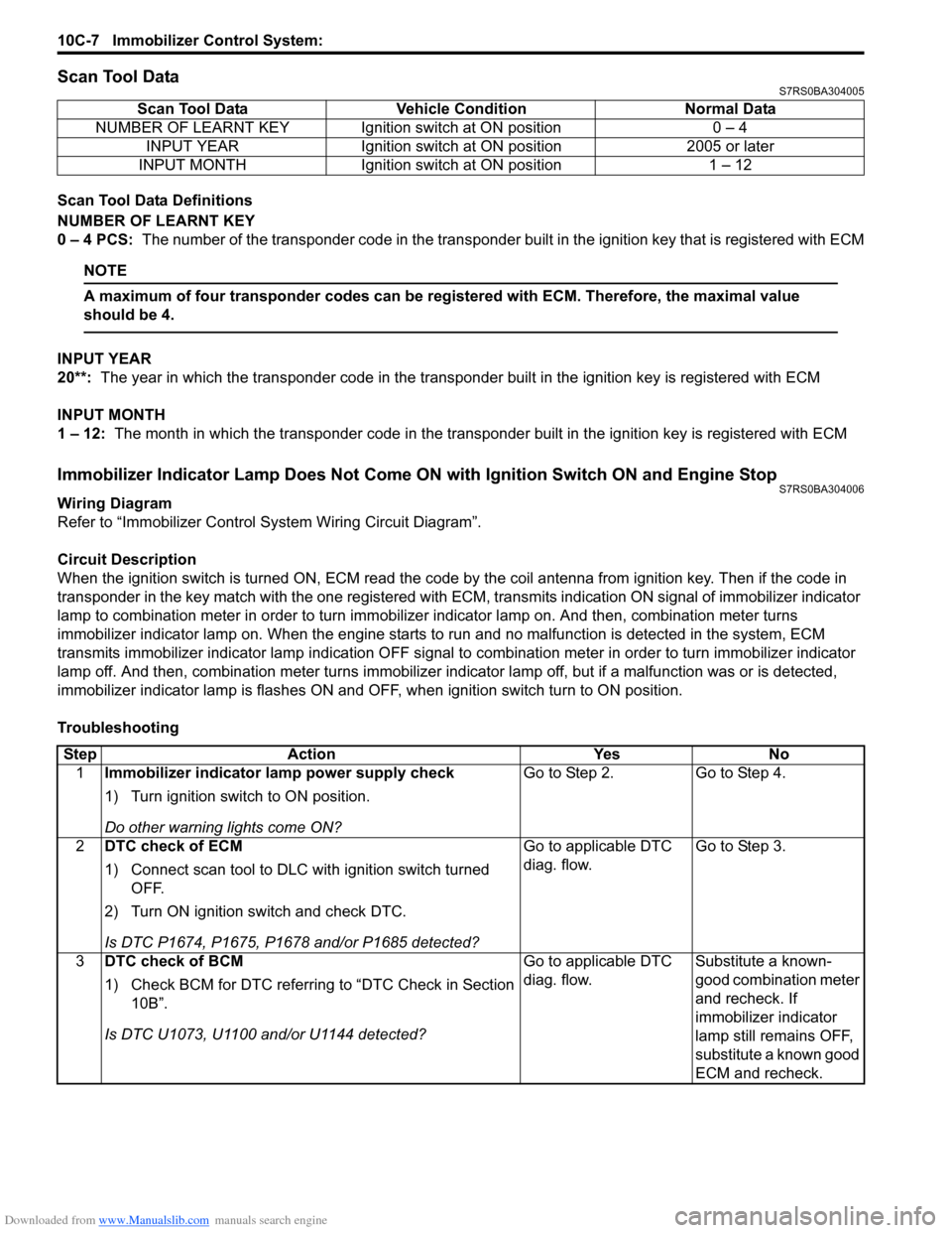
Scan Tool DataS7RS0BA304005
Scan Tool Data Definitions
NUMBER OF LEARNT KEY
0 – 4 PCS: The number of the transponder code in the transponder built in the ignition key that is registered with ECM
NOTE
A maximum of four transponder codes can be registered with ECM. Therefore, the maximal value
should be 4.
INPUT YEAR
20**: The year in which the transponder code in the transpon der built in the ignition key is registered with ECM
INPUT MONTH
1 – 12: The month in which the transponder code in the transpond er built in the ignition key is registered with ECM
Immobilizer Indicator Lamp Does Not Come ON with Ignition Switch ON and Engine StopS7RS0BA304006
Wiring Diagram
Refer to “Immobilizer Control System Wiring Circuit Diagram”.
Circuit Description
When the ignition switch is turned ON, ECM read the code by the coil antenna from ignition key. Then if the code in
transponder in the key match with the one registered with ECM, transmits indication ON signal of immobilizer indicator
lamp to combination meter in order to turn immobilizer indicator lamp on. And then, combination meter turns
immobilizer indicator lamp on. When th e engine starts to run and no malfunction is detected in the system, ECM
transmits immobilizer indi cator lamp indication OFF signal to combination meter in order to turn immobilizer indicator
lamp off. And then, comb ination meter turns immobilizer indicator lamp off, but if a malfunction was or is detected,
immobilizer indicator lamp is flashes ON and OF F, when ignition switch turn to ON position.
Troubleshooting Scan Tool Data Vehicl
e Condition Normal Data
NUMBER OF LEARNT KEY Ignition switch at ON position 0 – 4 INPUT YEAR Ignition switch at ON position 2005 or later
INPUT MONTH Ignition switch at ON position 1 – 12
Step Action YesNo
1 Immobilizer indicator lamp power supply check
1) Turn ignition switch to ON position.
Do other warning lights come ON? Go to Step 2.
Go to Step 4.
2 DTC check of ECM
1) Connect scan tool to DLC with ignition switch turned
OFF.
2) Turn ON ignition switch and check DTC.
Is DTC P1674, P1675, P1678 and/or P1685 detected? Go to applicable DTC
diag. flow.
Go to Step 3.
3 DTC check of BCM
1) Check BCM for DTC referring to “DTC Check in Section
10B”.
Is DTC U1073, U1100 and/or U1144 detected? Go to applicable DTC
diag. flow.
Substitute a known-
good combination meter
and recheck. If
immobilizer indicator
lamp still remains OFF,
substitute a known good
ECM and recheck.
Page 1454 of 1496
Downloaded from www.Manualslib.com manuals search engine 10C-11 Immobilizer Control System:
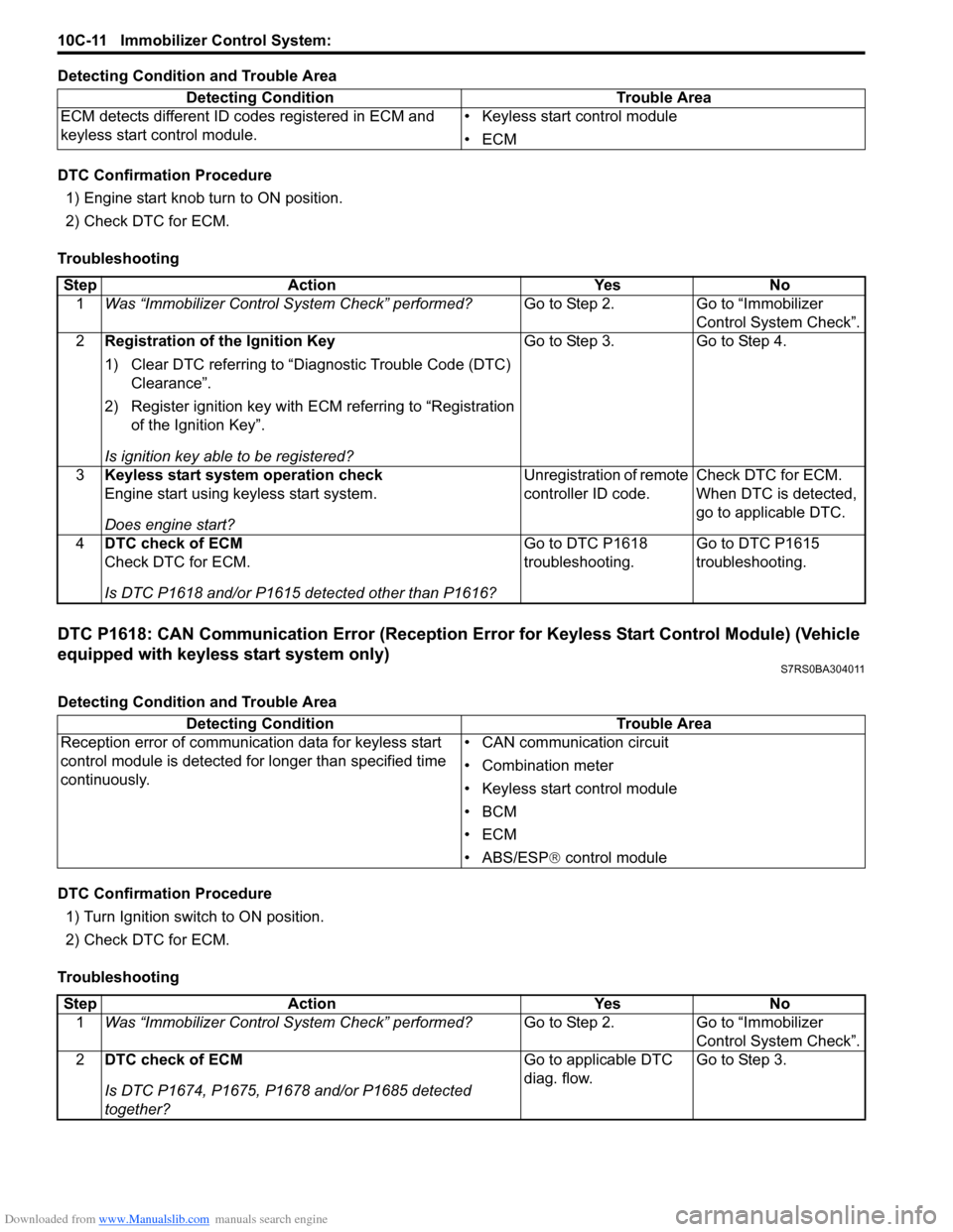
Detecting Condition and Trouble Area
DTC Confirmation Procedure1) Engine start knob turn to ON position.
2) Check DTC for ECM.
Troubleshooting
DTC P1618: CAN Communication Error (Reception Error for Keyless Start Control Module) (Vehicle
equipped with keyless start system only)
S7RS0BA304011
Detecting Condition and Trouble Area
DTC Confirmation Procedure 1) Turn Ignition switch to ON position.
2) Check DTC for ECM.
Troubleshooting Detecting Condition Trouble Area
ECM detects different ID codes registered in ECM and
keyless start control module. • Keyless start control module
•ECM
Step
Action YesNo
1 Was “Immobilizer Control S ystem Check” performed? Go to Step 2.Go to “Immobilizer
Control System Check”.
2 Registration of the Ignition Key
1) Clear DTC referring to “Diagnostic Trouble Code (DTC)
Clearance”.
2) Register ignition key with ECM referring to “Registration of the Ignition Key”.
Is ignition key able to be registered? Go to Step 3.
Go to Step 4.
3 Keyless start system operation check
Engine start using keyless start system.
Does engine start? Unregistration of remote
controller ID code.
Check DTC for ECM.
When DTC is detected,
go to applicable DTC.
4 DTC check of ECM
Check DTC for ECM.
Is DTC P1618 and/or P1615 detected other than P1616? Go to DTC P1618
troubleshooting.
Go to DTC P1615
troubleshooting.
Detecting Condition
Trouble Area
Reception error of communication data for keyless start
control module is detected for longer than specified time
continuously. • CAN communication circuit
• Combination meter
• Keyless start control module
•BCM
•ECM
• ABS/ESP®
control module
Step Action YesNo
1 Was “Immobilizer Control S ystem Check” performed? Go to Step 2.Go to “Immobilizer
Control System Check”.
2 DTC check of ECM
Is DTC P1674, P1675, P1678 and/or P1685 detected
together? Go to applicable DTC
diag. flow.
Go to Step 3.
Page 1466 of 1496
Downloaded from www.Manualslib.com manuals search engine 10E-4 Keyless Start System:
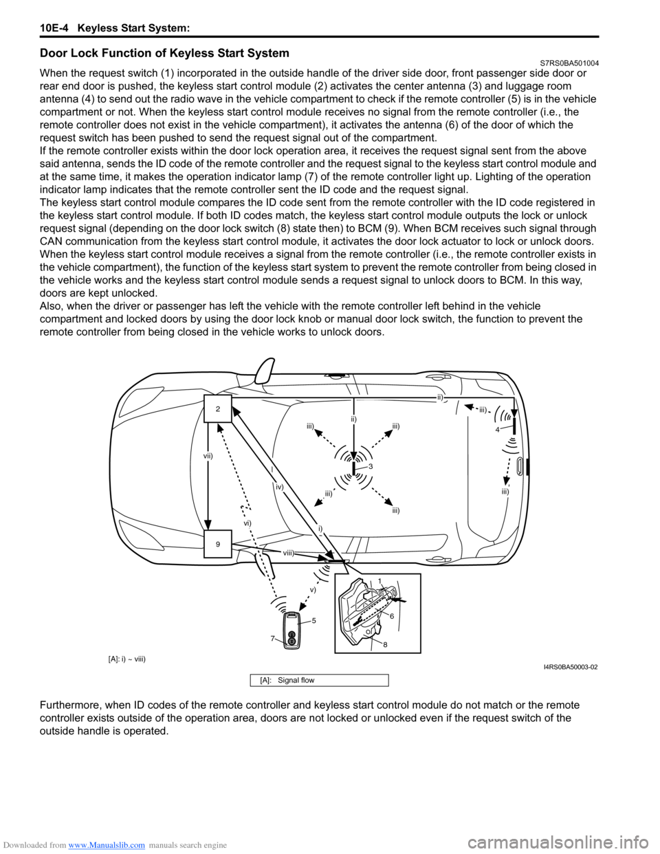
Door Lock Function of Keyless Start SystemS7RS0BA501004
When the request switch (1) incorporated in the outside handle of the driver side door, front passenger side door or
rear end door is pushed, the keyless start control modul e (2) activates the center antenna (3) and luggage room
antenna (4) to send out the radio wave in the vehicle compartm ent to check if the remote controller (5) is in the vehicle
compartment or not. When the keyless start control module receives no signal from the remote controller (i.e., the
remote controller does not exist in the vehicle compartment) , it activates the antenna (6) of the door of which the
request switch has been pushed to send the request signal out of the compartment.
If the remote controller exists within the door lock operati on area, it receives the request signal sent from the above
said antenna, sends the ID code of the remote controller and the request signal to the keyless start control module and
at the same time, it makes the operatio n indicator lamp (7) of the remote controller light up. Lighting of the operation
indicator lamp indicates that the remote controller sent the ID code and the request signal.
The keyless start control module compares the ID code sent from the remote controller with the ID code registered in
the keyless start control module. If both ID codes match, the keyless start control module outputs the lock or unlock
request signal (depending on the door lock switch (8) stat e then) to BCM (9). When BCM receives such signal through
CAN communication from the keyless start control module, it activates the door lock actuator to lock or unlock doors.
When the keyless start control module receiv es a signal from the remote controller (i.e., the remote controller exists in
the vehicle compartment), the function of the keyless start system to prevent the remote controller from being closed in
the vehicle works and the keyless start control module sends a request signal to unlock doors to BCM. In this way,
doors are kept unlocked.
Also, when the driver or passenger has left the vehicl e with the remote controller left behind in the vehicle
compartment and locked doors by using the door lock knob or manual door lock switch, the function to prevent the
remote controller from being closed in the vehicle works to unlock doors.
Furthermore, when ID codes of the remote controller and keyless start control module do not match or the remote
controller exists outside of the operation area, doors are not locked or unlocked even if the request switch of the
outside handle is operated.
9 2
vi)
v)
vii) iv)
i) ii)
iii)
iii)iii)
ii)
iii)
iii)
iii)
3
5
8
6
1 4
7
[A]: i) ~ viii)
viii)
I4RS0BA50003-02
[A]: Signal flow