2006 SUZUKI SWIFT passing
[x] Cancel search: passingPage 6 of 1496
Downloaded from www.Manualslib.com manuals search engine 00-1 Precautions:
Precautions
Precautions
Precautions
Precautions for Vehicles Equipped with a
Supplemental Restraint (Air Bag) System
S7RS0B0000001
WARNING!
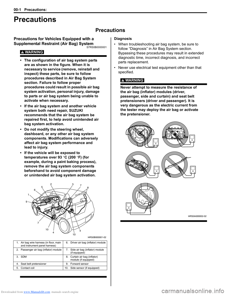
• The configuration of air bag system parts are as shown in the figure. When it is
necessary to service (remove, reinstall and
inspect) these parts, be sure to follow
procedures described in Air Bag System
section. Failure to follow proper
procedures could result in possible air bag
system activation, personal injury, damage
to parts or air bag system being unable to
activate when necessary.
• If the air bag system and another vehicle system both need repair, SUZUKI
recommends that the air bag system be
repaired first, to help avoid unintended air
bag system activation.
• Do not modify the steering wheel, dashboard, or any other air bag system
components. Modifications can adversely
affect air bag system performance and
lead to injury.
• If the vehicle will be exposed to temperatures over 93 °C (200 °F) (for
example, during a paint baking process),
remove the air bag system components
beforehand to avoid component damage
or unintended air bag system activation.
Diagnosis
• When troubleshooting air bag system, be sure to follow “Diagnosis” in Air Bag System section.
Bypassing these procedures may result in extended
diagnostic time, incorrect diagnosis, and incorrect
parts replacement.
• Never use electrical test equipment other than that specified.
WARNING!
Never attempt to measure the resistance of
the air bag (inflator) modules (driver,
passenger, side and curtain) and seat belt
pretensioners (driver and passenger). It is
very dangerous as the electric current from
the tester may deploy the air bag or activate
the pretensioner.
1. Air bag wire harness (in floor, main and instrument panel harness) 6. Driver air bag (inflator) module
2. Passenger air bag (inflator) module 7. Side air bag (inflator) module (if equipped)
3. SDM 8. Curtain air bag (inflator) module (if equipped)
4. Seat belt pretensioner 9. Forward sensor
5. Contact coil 10. Side sensor (if equipped)
1 2
3
4
4
5
6
7 7
8
9
10 10
I4RS0B000001-02
I4RS0A000002-02
Page 280 of 1496
Downloaded from www.Manualslib.com manuals search engine 1C-8 Engine Electrical Devices:
Installation
Reverse removal procedure noting the following.
• Tighten heated oxygen sensor to specified torque.Tightening torque
Heated oxygen sensor (a): 45 N·m (4.5 kgf-m,
32.5 lb-ft)
• Install exhaust manifold referring to “Exhaust Manifold Removal and Installation in Section 1K”, if removed.
• Connect connector of heated oxygen sensor and clamp wire harness securely.
• After installing heated oxygen sensor, start engine and check that no exhaust gas leakage exists.
CMP Sensor Removal and InstallationS7RS0B1306012
Removal
1) Disconnect negative (–) cable at battery.
2) Disconnect connector from CMP sensor.
3) Remove CMP sensor from cylinder head.
Installation 1) Install CMP sensor to cylinder head.
Tightening torque
CMP sensor bolt (a): 10 N·m (1.0 kgf-m, 7.5 lb-ft)
2) Connect connector to CMP sensor securely.
3) Connect negative (–) cable to battery.
Camshaft Position (CMP) Sensor InspectionS7RS0B1306013
Visual check
• Check that O-ring is free from damage.
• Check that end face of sensor and signal rotor tooth are free from any metal particles and damage.
Performance check 1) Remove metal particles on end face of CMP sensor, if any.
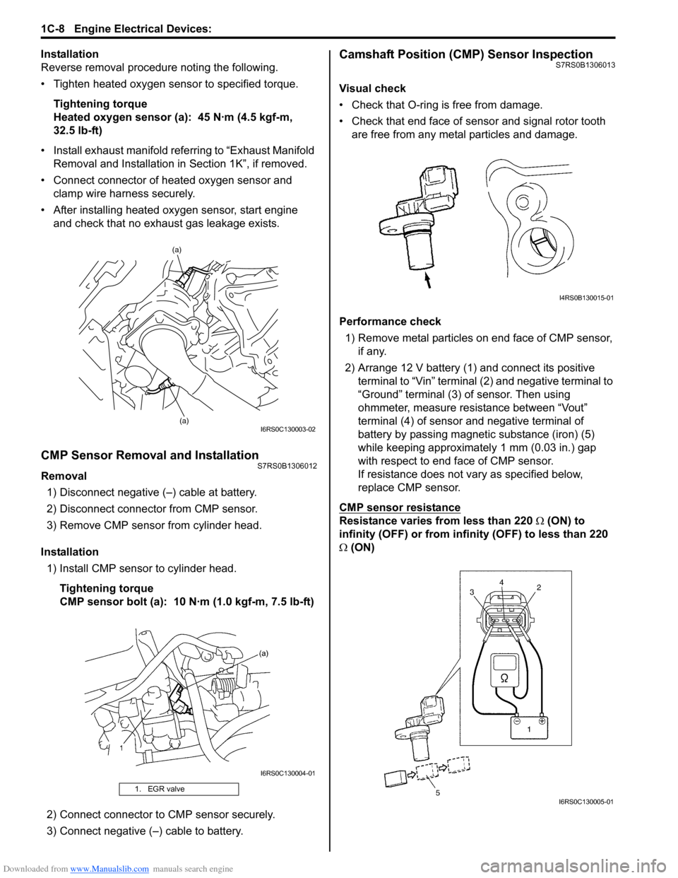
2) Arrange 12 V battery (1) and connect its positive terminal to “Vin” terminal (2) and negative terminal to
“Ground” terminal (3) of sensor. Then using
ohmmeter, measure resistance between “Vout”
terminal (4) of sensor and negative terminal of
battery by passing magnetic substance (iron) (5)
while keeping approximately 1 mm (0.03 in.) gap
with respect to end face of CMP sensor.
If resistance does not vary as specified below,
replace CMP sensor.
CMP sensor resistance
Resistance varies from less than 220 Ω (ON) to
infinity (OFF) or from infinity (OFF) to less than 220
Ω (ON)
1. EGR valve
(a)
(a)
I6RS0C130003-02
I6RS0C130004-01
I4RS0B130015-01
I6RS0C130005-01
Page 281 of 1496
Downloaded from www.Manualslib.com manuals search engine Engine Electrical Devices: 1C-9
CKP Sensor Removal and InstallationS7RS0B1306014
Removal1) Disconnect negative (–) cable at battery.
2) Remove generator drive belt refer to “Water Pump / Generator Drive Belt Remo val and Installation in
Section 1J”.
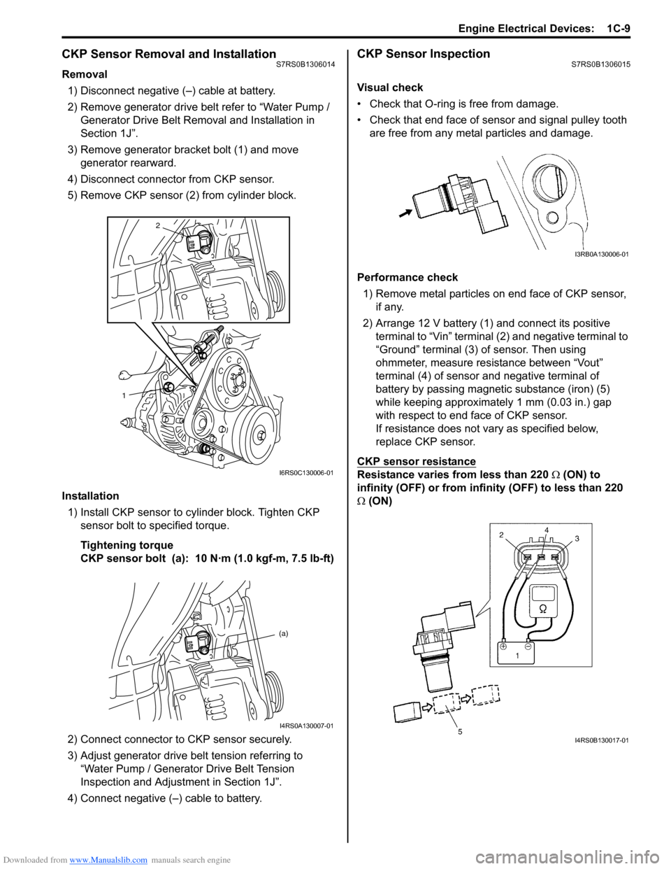
3) Remove generator bracket bolt (1) and move generator rearward.
4) Disconnect connector from CKP sensor.
5) Remove CKP sensor (2) from cylinder block.
Installation 1) Install CKP sensor to cylinder block. Tighten CKP sensor bolt to specified torque.
Tightening torque
CKP sensor bolt (a): 10 N·m (1.0 kgf-m, 7.5 lb-ft)
2) Connect connector to CKP sensor securely.
3) Adjust generator drive belt tension referring to “Water Pump / Generator Drive Belt Tension
Inspection and Adjustment in Section 1J”.
4) Connect negative (–) cable to battery.
CKP Sensor InspectionS7RS0B1306015
Visual check
• Check that O-ring is free from damage.
• Check that end face of sensor and signal pulley tooth are free from any metal particles and damage.
Performance check 1) Remove metal particles on end face of CKP sensor, if any.
2) Arrange 12 V battery (1) and connect its positive terminal to “Vin” terminal (2) and negative terminal to
“Ground” terminal (3) of sensor. Then using
ohmmeter, measure resistance between “Vout”
terminal (4) of sensor and negative terminal of
battery by passing magnetic substance (iron) (5)
while keeping approximately 1 mm (0.03 in.) gap
with respect to end face of CKP sensor.
If resistance does not vary as specified below,
replace CKP sensor.
CKP sensor resistance
Resistance varies from less than 220 Ω (ON) to
infinity (OFF) or from infinity (OFF) to less than 220
Ω (ON)
2
1
I6RS0C130006-01
(a)
I4RS0A130007-01
I3RB0A130006-01
I4RS0B130017-01
Page 353 of 1496
Downloaded from www.Manualslib.com manuals search engine Engine Lubrication System: 1E-1
Engine
Engine Lubrication System
General Description
Engine Lubrication DescriptionS7RS0B1501001
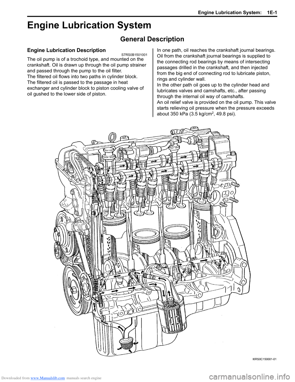
The oil pump is of a trochoid type, and mounted on the
crankshaft. Oil is drawn up through the oil pump strainer
and passed through the pump to the oil filter.
The filtered oil flows into two paths in cylinder block.
The filtered oil is passed to the passage in heat
exchanger and cylinder block to piston cooling valve of
oil gushed to the lower side of piston. In one path, oil reaches the crankshaft journal bearings.
Oil from the crankshaft journal bearings is supplied to
the connecting rod bearings by means of intersecting
passages drilled in the cran
kshaft, and then injected
from the big end of connecting rod to lubricate piston,
rings and cylinder wall.
In the other path oil goes up to the cylinder head and
lubricates valves and camshafts, etc., after passing
through the internal oil way of camshafts.
An oil relief valve is provided on the oil pump. This valve
starts relieving oil pressure when the pressure exceeds
about 350 kPa (3.5 kg/cm
2, 49.8 psi).
I6RS0C150001-01
Page 770 of 1496

Downloaded from www.Manualslib.com manuals search engine 5A-126 Automatic Transmission/Transaxle:
Reassembly
Reverse disassembly procedure for assembly, noting the
following points.
• Use new seal ring and O-ring. Apply A/T fluid before installation.
• Do not damage direct clutch return spring subassembly (1) and piston by pressing in direct
clutch return spring subassembly passing through its
original installing position over 0.7 mm (0.027 in.).
Special tool
(A): 09926–98310
• Apply A/T fluid to direct cl utch separator plates (4),
discs (3) and retaining plate (2).
• Install direct clutch separator plates (4), discs (3), retaining plate (2) and snap ring (1) to input shaft
subassembly.
• Install plate snap ring so that its both ends would be positioned in correct locations as shown in figure. • After assembly, measure direct clutch piston stroke.
Special tool
(A): 09900–20607
(B): 09900–20701
Direct clutch piston stroke
0.4 – 0.7 mm (0.016 – 0.027 in.)
When piston stroke is out of specification, select direct
clutch retaining plate with suitable thickness from
among the following table and replace it.
Available direct clutch retaining plate thickness
I2RH0B510168-01
I2RH0B510169-01
[A]: Correct [B]: Incorrect
ThicknessIdentification mark
3.0 mm (0.118 in.) 1
3.2 mm (0.126 in.) 2
3.4 mm (0.134 in.) 3
2.8 mm (0.110 in.) 4
1. Direct clutch assembly 3. Oil hole
2. Oil pump assembly
I2RH0B510170-01
I2RH0B510171-01
Page 775 of 1496

Downloaded from www.Manualslib.com manuals search engine Automatic Transmission/Transaxle: 5A-131
Reassembly
Reverse disassembly procedure for assembly, noting the
following points.
• Before assembling, apply automatic transaxle fluid to component parts.
• Replace O-rings and seal ring with new ones.
• Do not damage forward clutch return spring subassembly and balancer (1) by pressing forward
clutch return spring subassembly passing through its
original installing position over 1.5 mm (0.059 in.).
Special tool
(A): 09926–97610
• Apply A/T fluid to forward clutch separator plates (1), discs (2) and retaining plate (3).
• Install forward clutch separator plates (1), discs (2) and retaining plate (3), then snap ring (4) to forward
clutch drum. • Install forward clutch plate snap ring so that its both
ends would be positioned in correct locations as
shown in figure.
I2RH0B510180-01
4
1
2 3
I5RW0C510062-01
[A]: Correct
[B]: Incorrect
I2RH0B510188-01
Page 781 of 1496
Downloaded from www.Manualslib.com manuals search engine Automatic Transmission/Transaxle: 5A-137
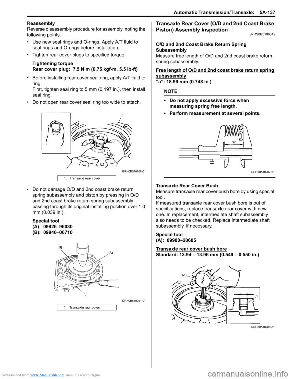
Reassembly
Reverse disassembly procedure for assembly, noting the
following points.
• Use new seal rings and O-rings. Apply A/T fluid to seal rings and O-rings before installation.
• Tighten rear cover plugs to specified torque.
Tightening torque
Rear cover plug: 7.5 N·m (0.75 kgf-m, 5.5 lb-ft)
• Before installing rear cover seal ring, apply A/T fluid to ring.
First, tighten seal ring to 5 mm (0.197 in.), then install
seal ring.
• Do not open rear cover seal ring too wide to attach.
• Do not damage O/D and 2nd coast brake return spring subassembly and piston by pressing in O/D
and 2nd coast brake return spring subassembly
passing through its original installing position over 1.0
mm (0.039 in.).
Special tool
(A): 09926–96030
(B): 09946–06710Transaxle Rear Cover (O/D and 2nd Coast Brake
Piston) Assembly Inspection
S7RS0B5106049
O/D and 2nd Coast Brake Return Spring
Subassembly
Measure free length of O/D and 2nd coast brake return
spring subassembly.
Free length of O/D and 2nd coast brake return spring
subassembly
“a”: 18.99 mm (0.748 in.)
NOTE
• Do not apply excessive force when measuring spring free length.
• Perform measurement at several points.
Transaxle Rear Cover Bush
Measure transaxle rear cover bush bore by using special
tool.
If measured transaxle rear cover bush bore is out of
specifications, replace transaxle rear cover with new
one. In replacement, inte rmediate shaft subassembly
also needs to be checked. Replace intermediate shaft
subassembly, if necessary.
Special tool
(A): 09900–20605
Transaxle rear cover bush bore
Standard: 13.94 – 13.96 mm (0.549 – 0.550 in.)
1. Transaxle rear cover
1. Transaxle rear cover
I2RH0B510206-01
I2RH0B510201-01
I2RH0B510207-01
I2RH0B510208-01
Page 795 of 1496

Downloaded from www.Manualslib.com manuals search engine Automatic Transmission/Transaxle: 5A-151
6) Install parking lock pawl bracket (1) to transaxle
case.
Tightening torque
Parking lock pawl bracket bolt (a): 7.5 N·m (0.75
kgf-m, 5.5 lb-ft)
7) After applying A/T fluid to new O-rings, install them to 1st and reverse brake piston (3).
8) Install 1st and reverse brake piston (1) to transaxle case (2).
NOTE
Be careful not to damage O-ring when
installing 1st and reverse brake piston.
9) Install 1st and reverse brake return spring subassembly (1) to transaxle case (2).
10) Apply A/T fluid to 1st and reverse brake discs (2), separator plates (3) and retaining plate (1), then
install them to transaxle case.
11) Compress 1st and reverse brake return spring using special tool and hydraulic press, then attach snap
ring.
CAUTION!
Do not damage 1st and reverse brake return
spring subassembly discs, plates and piston
by pressing in 1st and reverse brake return
spring subassembly passing through its
original installing position over 0.8 mm (0.031
in.).
Special tool
(A): 09926–97620
1. Inner O-ring 2. Outer O-ring
I2RH0B510262-01
I2RH0B510263-01
I2RH0B510264-01
I2RH0B510265-01
I2RH0B510266-01
I2RH0B510267-01