Page 1437 of 1496

Downloaded from www.Manualslib.com manuals search engine Body Electrical Control System: 10B-34
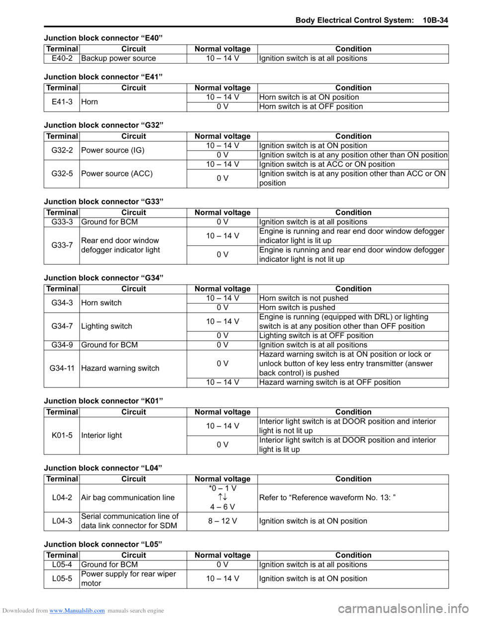
Junction block connector “E40”
Junction block connector “E41”
Junction block connector “G32”
Junction block connector “G33”
Junction block connector “G34”
Junction block connector “K01”
Junction block connector “L04”
Junction block connector “L05”Terminal Circuit Normal voltage Condition
E40-2 Backup power source 10 – 14 V Igni tion switch is at all positions
TerminalCircuitNormal voltage Condition
E41-3 Horn 10 – 14 V Horn switch is at ON position
0 V Horn switch is at OFF position
Terminal CircuitNormal voltage Condition
G32-2 Power source (IG) 10 – 14 V Ignition switch is at ON position
0 V Ignition switch is at any position other than ON position
G32-5 Power source (ACC) 10 – 14 V Ignition switch is at ACC or ON position
0 V Ignition switch is at any position other than ACC or ON
position
Terminal
CircuitNormal voltage Condition
G33-3 Ground for BCM 0 V Ignition switch is at all positions
G33-7 Rear end door window
defogger indicator light 10 – 14 V
Engine is running and rear end door window defogger
indicator light is lit up
0 V Engine is running and rear end door window defogger
indicator light is not lit up
Terminal
CircuitNormal voltage Condition
G34-3 Horn switch 10 – 14 V Horn switch is not pushed
0 V Horn switch is pushed
G34-7 Lighting switch 10 – 14 VEngine is running (equipped with DRL) or lighting
switch is at any position other than OFF position
0 V Lighting switch is at OFF position
G34-9 Ground for BCM 0 V Ignition switch is at all positions
G34-11 Hazard warning switch 0 VHazard warning switch is at
ON position or lock or
unlock button of key less entry transmitter (answer
back control) is pushed
10 – 14 V Hazard warning switch is at OFF position
Terminal CircuitNormal voltage Condition
K01-5 Interior light 10 – 14 V
Interior light switch is at
DOOR position and interior
light is not lit up
0 V Interior light switch is at
DOOR position and interior
light is lit up
Terminal CircuitNormal voltage Condition
L04-2 Air bag communication line *0 – 1 V
↑↓
4 – 6 V Refer to “Reference
waveform No. 13: ”
L04-3 Serial communication line of
data link connector for SDM 8 – 12 V Ignition switch is at ON position
Terminal
CircuitNormal voltage Condition
L05-4 Ground for BCM 0 V Ignition switch is at all positions
L05-5 Power supply for rear wiper
motor 10 – 14 V Ignition switch is at ON position
Page 1447 of 1496

Downloaded from www.Manualslib.com manuals search engine Immobilizer Control System: 10C-4
Schematic and Routing Diagram
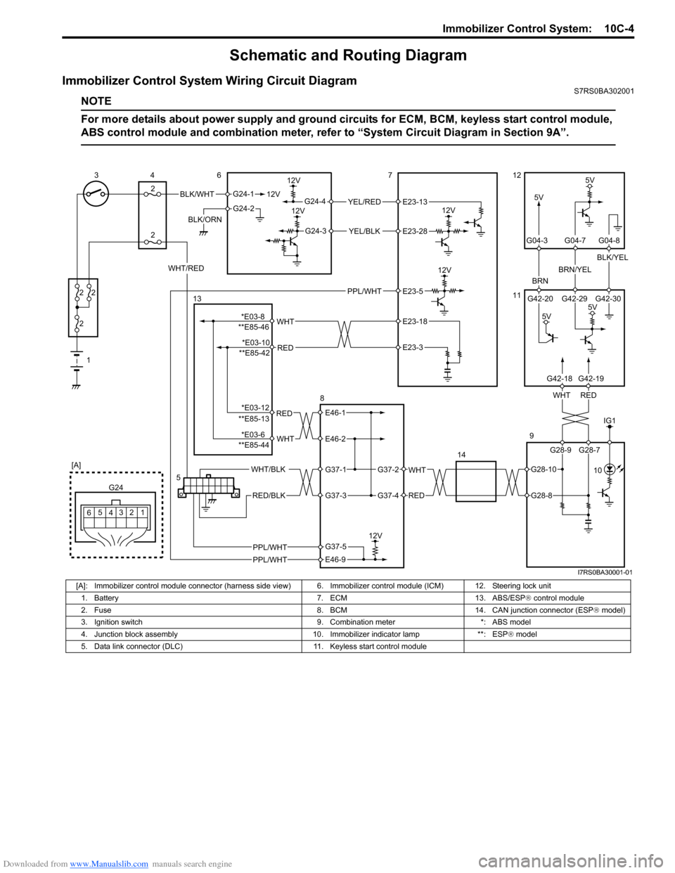
Immobilizer Control System Wiring Circuit DiagramS7RS0BA302001
NOTE
For more details about power supply and ground circuits for ECM, BCM, keyless start control module,
ABS control module and combination meter, refer to “System Ci rcuit Diagram in Section 9A”.
BLK/WHT
BLK/ORN12V
G24-1
G24-2
12V
5V
12V
12VYEL/RED
YEL/BLK
G24-4
G24-3
12V
5V
BRN
BRN/YEL
BLK/YEL
1
2
2 2
2
34
2 6712
11
9
14
12
3
4
G24
[A]
5
6
REDWHT
G42-20 G42-29 G42-30
G04-3 G04-7 G04-8
WHT/RED
5V
5V
5
G28-9 G28-7
G42-18G42-19
E23-13
E23-28
IG1
PPL/WHT 10
PPL/WHT
PPL/WHT
E23-5
RED
WHT**E85-46E23-18
E23-3
RED
WHT
E46-1
E46-2
WHT
RED
G37-2
G37-4
WHT/BLK
RED/BLK
G37-1
G37-3
12V
E46-9
G37-5
13
8
**E85-42
**E85-13
**E85-44
G28-10
G28-8
*E03-8 *E03-10
*E03-12
*E03-6
I7RS0BA30001-01
[A]: Immobilizer control module connector (harness side vi ew) 6. Immobilizer control module (ICM) 12. Steering lock unit
1. Battery 7. ECM 13. ABS/ESP ® control module
2. Fuse 8. BCM 14. CAN junction connector (ESP ® model)
3. Ignition switch 9. Combination meter *: ABS model
4. Junction block assembly 10. Immobilizer indicator lamp **: ESP ® model
5. Data link connector (DLC) 11. Keyless start control module
Page 1460 of 1496

Downloaded from www.Manualslib.com manuals search engine 10C-17 Immobilizer Control System:
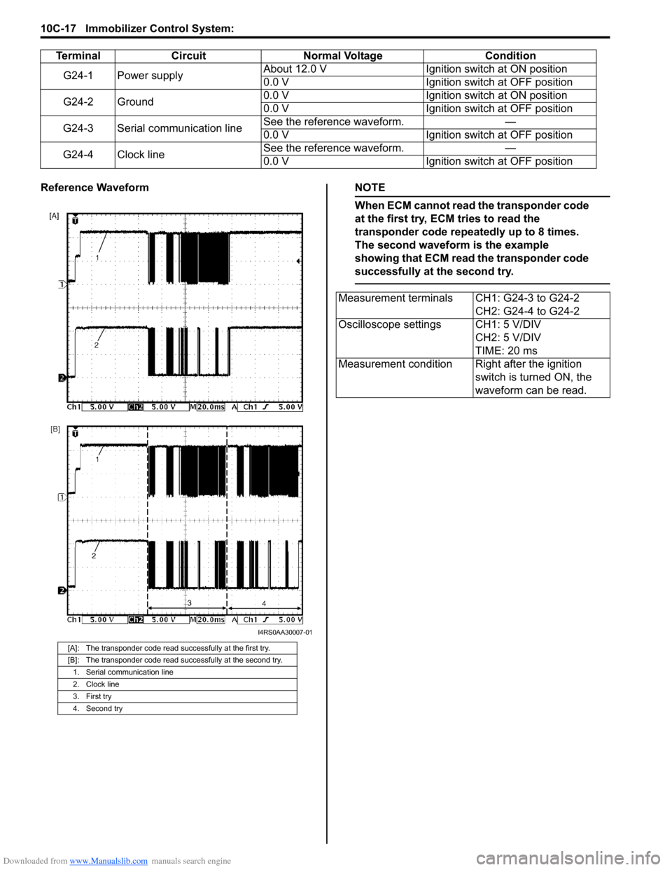
Reference WaveformNOTE
When ECM cannot read the transponder code
at the first try, ECM tries to read the
transponder code repeatedly up to 8 times.
The second waveform is the example
showing that ECM read the transponder code
successfully at the second try.
TerminalCircuit Normal Voltage Condition
G24-1 Power supply About 12.0 V
Ignition switch at ON position
0.0 V Ignition switch at OFF position
G24-2 Ground 0.0 V
Ignition switch at ON position
0.0 V Ignition switch at OFF position
G24-3 Serial communication line See the reference waveform.
—
0.0 V Ignition switch at OFF position
G24-4 Clock line See the reference waveform.
—
0.0 V Ignition switch at OFF position
[A]: The transponder code read successfully at the first try.
[B]: The transponder code read successfully at the second try.
1. Serial communication line
2. Clock line
3. First try
4. Second try
I4RS0AA30007-01
Measurement terminals CH1: G24-3 to G24-2 CH2: G24-4 to G24-2
Oscilloscope settings CH1: 5 V/DIV CH2: 5 V/DIV
TIME: 20 ms
Measurement condition Right after the ignition switch is turned ON, the
waveform can be read.
Page 1487 of 1496

Downloaded from www.Manualslib.com manuals search engine Keyless Start System: 10E-25
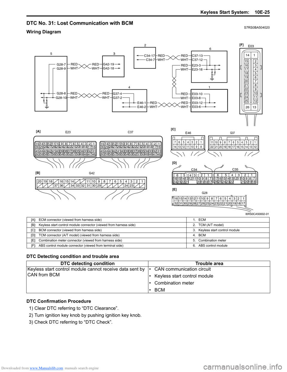
DTC No. 31: Lost Communication with BCMS7RS0BA504020
Wiring Diagram
DTC Detecting condition and trouble area
DTC Confirmation Procedure1) Clear DTC referring to “DTC Clearance”.
2) Turn ignition key knob by pushing ignition key knob.
3) Check DTC referring to “DTC Check”.
REDWHTE03-12E03-6
REDWHTE03-10E03-8
REDWHTREDWHTG42-19G42-18 3REDWHTREDWHT
REDWHTREDWHT
REDWHTE46-1
G37-4
G42-19G42-18
G28-8G28-10G37-2
C34-7
E46-2
C34-17
1
2
4
53
21
[A]
E23
G42 C37
34
1819
5671011
17
20
47 46
495051
2122
52 16
25 9
24
14
29
5557 54 53
59
60 58 2
262728
15
30
56 4832 31343536374042 39 38
44
45 43 41 331
1213
238
34
1819
5671011
17
20
47 46
495051
2122
52 16
25 9
24
14
29
5557 54 53
59
60 5826
27
28
15
30
56 4832 31343536374042 39 38
44
45 43 41 33
1213
238
[B] [D]
[C]
65
16 15141312 11 43
24 23 2122 10 9 8 7
21
1920 18 17
C34
17 16
26 25 15 14
65 3
42
13 12
23 2224 1110 9
212019 87
18
1
C35
[E]G28
12345678910111213141516
17181920212223242526272829303132
124
53
67
891011
1213141516171819202122
G37
E46
124
53
67
891011121314
1234567891011
141516
36 34 33 32 31 30 29 24 23
37
181920
G28-9G28-7REDWHTE23-3E23-18
REDWHTC37-13C37-12 6
[F]
E03
15
16
17
18
19
20
21
22
23
24
25 2
3
4
5
6
7
8
9
10
11
12
1
13
14
26
I6RS0CA50002-01
[A]: ECM connector (viewed from harness side)
1. ECM
[B]: Keyless start control module connector (v iewed from harness side) 2. TCM (A/T model)
[C]: BCM connector (viewed from harness side) 3. Keyless start control module
[D]: TCM connector (A/T model) (viewed from harness side) 4. BCM
[E]: Combination meter connector (viewed from harness side) 5. Combination meter
[F]: ABS control module connector (viewed from terminal side) 6. ABS control module
DTC detecting conditionTrouble area
Keyless start control module cannot receive data sent by
CAN from BCM • CAN communication circuit
• Keyless start control module
• Combination meter
•BCM