2006 SUZUKI SWIFT ignition system immobilizer
[x] Cancel search: ignition system immobilizerPage 4 of 1496

Downloaded from www.Manualslib.com manuals search engine 00
0
1
2
3
4
5
6
7
8
9
10
11
Vo l u m e 1
Precautions............................................................... 00-iPrecautions ............................................................ 00-1
General Information ................ ................................... 0-i
General Information ............................................... 0A-1
Maintenance and Lubricatio n ................................. 0B-1
Engine ......................................................................... 1-i Precautions .............................................................. 1-1
Engine General Information and Diagnosis ........... 1A-1
Aux. Emission Control Devices .............................. 1B-1
Engine Electrical Devices....................................... 1C-1
Engine Mechanical ................................................. 1D-1
Engine Lubrication System .................................... 1E-1
Engine Cooling System .......................................... 1F-1
Fuel System ...........................................................1G-1
Ignition System....................................................... 1H-1
Starting System ....................................................... 1I-1
Charging System.....................................................1J-1
Exhaust System ..................................................... 1K-1
Suspension ................................................................. 2-i Precautions .............................................................. 2-1
Suspension General Diagnosis .............................. 2A-1
Front Suspension ................................................... 2B-1
Rear Suspension................ .................................... 2C-1
Wheels and Tires ................................................... 2D-1
Driveline / Axle ........................................................... 3-i Precautions .............................................................. 3-1
Drive Shaft / Axle ................................................... 3A-1
Brakes ......................................................................... 4-i Precautions .............................................................. 4-1
Brake Control System and Diagnosis .................... 4A-1
Front Brakes........................................................... 4B-1
Rear Brakes ........................................................... 4C-1
Parking Brake......................................................... 4D-1
ABS ........................................................................ 4E-1
Electronic Stability Program ................................... 4F-1
Vo l u m e 2
Precautions ............................................................... 00-iPrecautions ............................................................ 00-1
Transmission / Transaxle .... ...................................... 5-i
Precautions .............................................................. 5-1
Automatic Transmission/Transaxle ........................ 5A-1
Manual Transmission/Transaxle ............................ 5B-1
Clutch .....................................................................5C-1
Steering ....................................................................... 6-i Precautions .............................................................. 6-1
Steering General Diagnosis ................................... 6A-1
Steering Wheel and Column .................................. 6B-1
Power Assisted Steering System ...........................6C-1
HVAC ........................................................................... 7-i Precautions .............................................................. 7-1
Heater and Ventilation............................................ 7A-1
Air Conditioning System ......................................... 7B-1
Restraint ...................................................................... 8-i Precautions .............................................................. 8-1
Seat Belts ............................................................... 8A-1
Air Bag System ...................................................... 8B-1
Body, Cab and Accessories .... .................................. 9-i
Precautions .............................................................. 9-1
Wiring Systems ...................................................... 9A-1
Lighting Systems .................................................... 9B-1
Instrumentation / Driver Info. / Horn .......................9C-1
Wipers / Washers ...................................................9D-1
Glass / Windows / Mirrors ...................................... 9E-1
Security and Locks ................................................. 9F-1
Seats ..................................................................... 9G-1
Interior Trim ............................................................9H-1
Hood / Fenders / Doors .......................................... 9J-1
Body Structure ....................................................... 9K-1
Paint / Coatings ...................................................... 9L-1
Exterior Trim .......................................................... 9M-1
Control Systems ....................................................... 10-i Precautions ............................................................ 10-1
Body Electrical Control Sy stem ............................ 10B-1
Immobilizer Control System .................................10C-1
Keyless Start System ........................................... 10E-1
TABLE OF CONTENTS
Page 22 of 1496
Downloaded from www.Manualslib.com manuals search engine 0A-1 General Information:
General Information
General Information
General Description
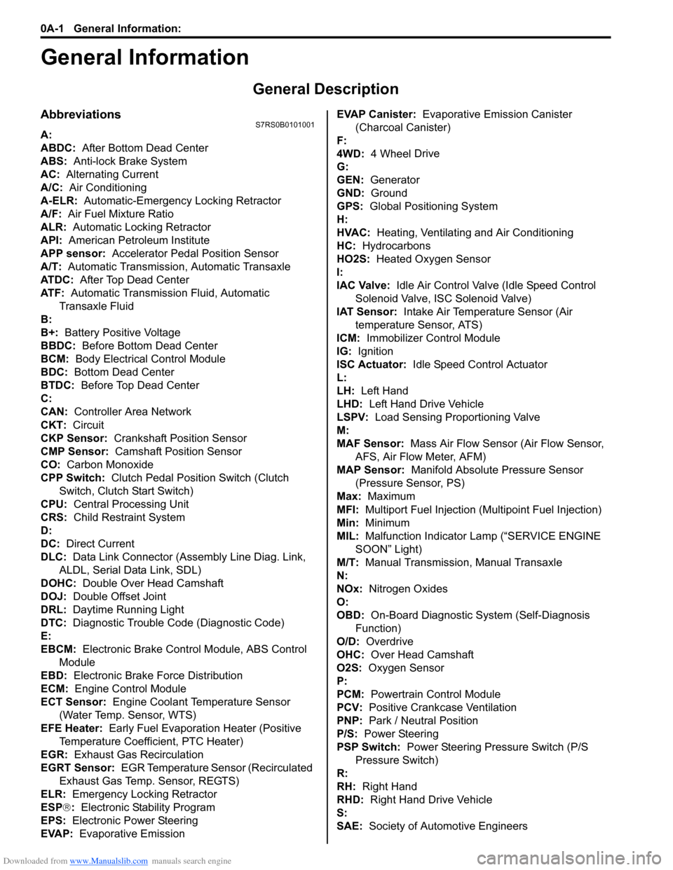
AbbreviationsS7RS0B0101001
A:
ABDC: After Bottom Dead Center
ABS: Anti-lock Brake System
AC: Alternating Current
A/C: Air Conditioning
A-ELR: Automatic-Emergency Locking Retractor
A/F: Air Fuel Mixture Ratio
ALR: Automatic Locking Retractor
API: American Petroleum Institute
APP sensor: Accelerator Pedal Position Sensor
A/T: Automatic Transmission , Automatic Transaxle
AT D C : After Top Dead Center
ATF: Automatic Transmission Fluid, Automatic
Transaxle Fluid
B:
B+: Battery Positive Voltage
BBDC: Before Bottom Dead Center
BCM: Body Electrical Control Module
BDC: Bottom Dead Center
BTDC: Before Top Dead Center
C:
CAN: Controller Area Network
CKT: Circuit
CKP Sensor: Crankshaft Position Sensor
CMP Sensor: Camshaft Position Sensor
CO: Carbon Monoxide
CPP Switch: Clutch Pedal Position Switch (Clutch
Switch, Clutch Start Switch)
CPU: Central Processing Unit
CRS: Child Restraint System
D:
DC: Direct Current
DLC: Data Link Connector (Assembly Line Diag. Link,
ALDL, Serial Data Link, SDL)
DOHC: Double Over Head Camshaft
DOJ: Double Offset Joint
DRL: Daytime Running Light
DTC: Diagnostic Trouble Code (Diagnostic Code)
E:
EBCM: Electronic Brake Cont rol Module, ABS Control
Module
EBD: Electronic Brake Force Distribution
ECM: Engine Control Module
ECT Sensor: Engine Coolant Temperature Sensor (Water Temp. Sensor, WTS)
EFE Heater: Early Fuel Evaporation Heater (Positive
Temperature Coefficient, PTC Heater)
EGR: Exhaust Gas Recirculation
EGRT Sensor: EGR Temperature Sensor (Recirculated
Exhaust Gas Temp. Sensor, REGTS)
ELR: Emergency Locking Retractor
ESP ®: Electronic Stability Program
EPS: Electronic Power Steering
EVAP: Evaporative Emission EVAP Canister:
Evaporative Emission Canister
(Charcoal Canister)
F:
4WD: 4 Wheel
Drive
G:
GEN: Generator
GND: Ground
GPS: Global Positioning System
H:
HVAC: Heating, Ventilating and Air Conditioning
HC: Hydrocarbons
HO2S: Heated Oxygen Sensor
I:
IAC Valve: Idle Air Control Valve (Idle Speed Control
Solenoid Valve, ISC Solenoid Valve)
IAT Sensor: Intake Air Temperature Sensor (Air
temperature Sensor, ATS)
ICM: Immobilizer Control Module
IG: Ignition
ISC Actuator: Idle Speed Control Actuator
L:
LH: Left Hand
LHD: Left Hand Drive Vehicle
LSPV: Load Sensing Proportioning Valve
M:
MAF Sensor: Mass Air Flow Sensor (Air Flow Sensor, AFS, Air Flow Meter, AFM)
MAP Sensor: Manifold Absolute Pressure Sensor
(Pressure Sensor, PS)
Max: Maximum
MFI: Multiport Fuel Injection (Mu ltipoint Fuel Injection)
Min: Minimum
MIL: Malfunction Indicator Lamp (“SERVICE ENGINE
SOON” Light)
M/T: Manual Transmission, Manual Transaxle
N:
NOx: Nitrogen Oxides
O:
OBD: On-Board Diagnostic System (Self-Diagnosis
Function)
O/D: Overdrive
OHC: Over Head Camshaft
O2S: Oxygen Sensor
P:
PCM: Powertrain Control Module
PCV: Positive Crankcase Ventilation
PNP: Park / Neutral Position
P/S: Power Steering
PSP Switch: Power Steering Pressure Switch (P/S
Pressure Switch)
R:
RH: Right Hand
RHD: Right Hand Drive Vehicle
S:
SAE: Society of Automotive Engineers
Page 62 of 1496
Downloaded from www.Manualslib.com manuals search engine 1A-12 Engine General Information and Diagnosis:
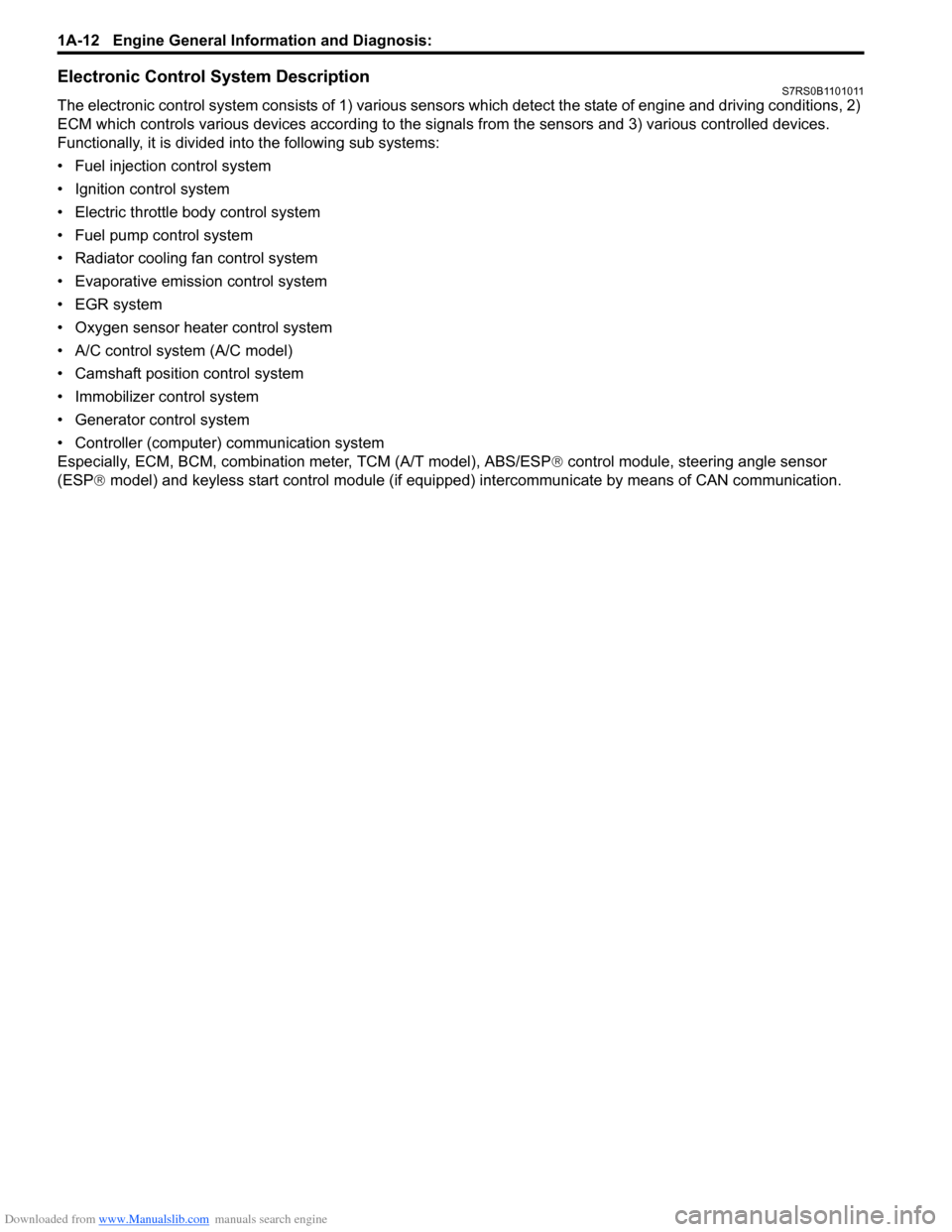
Electronic Control System DescriptionS7RS0B1101011
The electronic control system consists of 1) various sensors which detect the state of engine and driving conditions, 2)
ECM which controls various devices ac cording to the signals from the sensors and 3) various controlled devices.
Functionally, it is divided into the following sub systems:
• Fuel injection control system
• Ignition control system
• Electric throttle body control system
• Fuel pump control system
• Radiator cooling fan control system
• Evaporative emission control system
• EGR system
• Oxygen sensor heater control system
• A/C control system (A/C model)
• Camshaft position control system
• Immobilizer control system
• Generator control system
• Controller (computer) communication system
Especially, ECM, BCM, combination meter, TCM (A/T model), ABS/ESP ® control module, steering angle sensor
(ESP® model) and keyless start control module (if equipped) intercommunicate by means of CAN communication.
Page 63 of 1496
Downloaded from www.Manualslib.com manuals search engine Engine General Information and Diagnosis: 1A-13
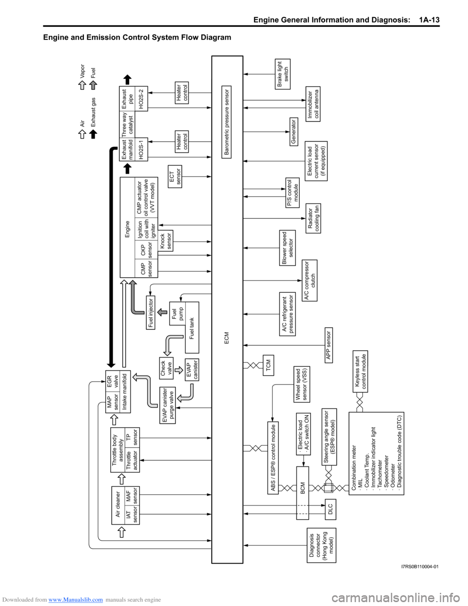
Engine and Emission Control System Flow Diagram
Intake manifold
Exhaust gas AirFuel
Va p o r
EVAP canister purge valve
ECM
Barometric pressure sensor
A/C compressor clutch
Generator
Immobilizer
coil antenna
P/S controlmodule
Brake light switch
Air cleaner
IAT
sensor MAF
sensor
A/C refrigerant
pressure sensor
TP
sensor
Throttle body
assembly
Throttle
actuator
Wheel speed
sensor (VSS)
Steering angle sensor (ESP® model)
ABS / ESP® control module
Blower speed
selector
MAP
sensor EGR
valve
Check valve
EVAP
canisterTCM
Exhaust
manifold Exhaust
pipe
Fuel injector
ECT
sensor
Heater
control
HO2S-1 HO2S-2
Engine
CMP
sensor CKP
sensor
Knock
sensor Ignition
coil with
igniter
Fuel tank
Fuel
pump CMP actuator
oil control valve (VVT model) Three way
catalyst
Heater
control
Radiator
cooling fan
Combination meter
· MIL
· Coolant Temp.
· Immobilizer indicator light
· Tachometer
· Speedometer
· Odometer
· Diagnostic trouble code (DTC)
Keyless start
control module
DLC
· Electric load
· A/C switch ON
BCM
Diagnosis
connector
(Hong Kong model) Electric load
current sensor (if equipped)
APP sensor
I7RS0B110004-01
Page 71 of 1496
Downloaded from www.Manualslib.com manuals search engine Engine General Information and Diagnosis: 1A-21
Component Location
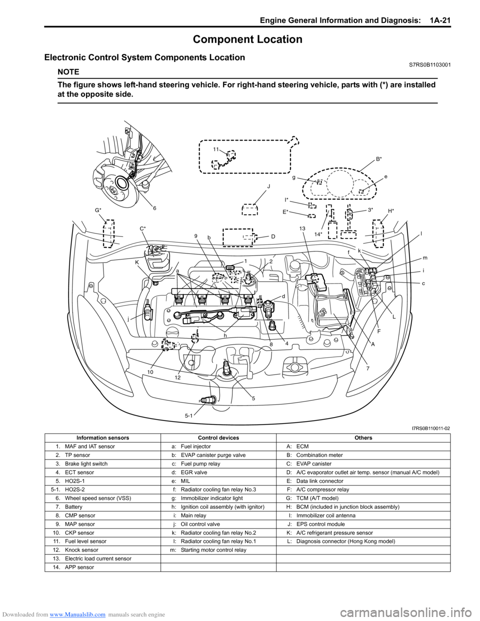
Electronic Control System Components LocationS7RS0B1103001
NOTE
The figure shows left-hand steering vehicle. For right-hand steering vehicle, parts with (*) are installed
at the opposite side.
I*
E*
G*
D
K H*
J
C*
7
A
F
c
L
i m
f
B*
e
g
k
l
13
3*
4
j
10 12 h
58
a
9
b
1
5-1
d
2
11
6
14*
I7RS0B110011-02
Information sensors Control devices Others
1. MAF and IAT sensor a: Fuel injectorA: ECM
2. TP sensor b: EVAP canister purge valve B: Combination meter
3. Brake light switch c: Fuel pump relayC: EVAP canister
4. ECT sensor d: EGR valveD: A/C evaporator outlet air temp. sensor (manual A/C model)
5. HO2S-1 e: MILE: Data link connector
5-1. HO2S-2 f: Radiator cooling fan relay No.3F: A/C compressor relay
6. Wheel speed sensor (VSS) g: Immobilizer indicator lightG: TCM (A/T model)
7. Battery h: Ignition coil assembly (with ignitor) H: BCM (included in junction block assembly)
8. CMP sensor i: Main relayI: Immobilizer coil antenna
9. MAP sensor j: Oil control valveJ: EPS control module
10. CKP sensor k: Radiator cooling fan relay No.2K: A/C refrigerant pressure sensor
11. Fuel level sensor l: Radiator cooling fan relay No.1L: Diagnosis connector (Hong Kong model)
12. Knock sensor m: Starting motor control relay
13. Electric load current sensor
14. APP sensor
Page 89 of 1496

Downloaded from www.Manualslib.com manuals search engine Engine General Information and Diagnosis: 1A-39
8Check ignition timing
1) Using SUZUKI scan tool, select “Misc Test” mode on
SUZUKI scan tool and fix ignition timing to initial one.
2) Using timing light (1), check initial ignition timing. Special tool
(A): 09930–76420
Is it 5
°± 3° BTDC at specif ied idle speed? Go to “Engine Symptom
Diagnosis”.
Check ignition control
related parts referring to
“Ignition Timing
Inspection in Section
1H”.
9 Check immobilizer system malfunction
1) Check immobilizer indica tor lamp for flashing.
Is it flashing when ignition switch is turned to ON position? Go to “Diagnostic
Trouble Code (DTC)
Check in Section 10C”.
Go to Step 10.
10 Check fuel supply
1) Check to make sure that enough fuel is filled in fuel tank.
2) Turn ON ignition switch for 2 seconds and then OFF.
3) Repeat Step 2) a few times.
Is fuel pressure felt from fuel feed hose when ignition switch
is turned ON? Go to Step 12. Go to Step 11.
Step Action Yes No
I2RH01110006-01
1, (A)
10
0I3RB0A180004-01
I3RM0A110014-01
Page 880 of 1496
Downloaded from www.Manualslib.com manuals search engine 6B-9 Steering Wheel and Column:
Ignition Switch Cylinder Assembly Removal
and Installation (Non- Keyless Start Model)
S7RS0B6206008
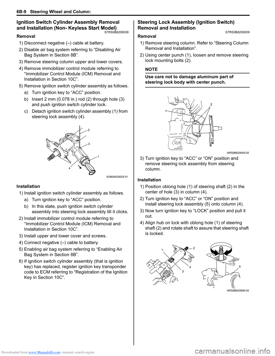
Removal1) Disconnect negative (–) cable at battery.
2) Disable air bag system referring to “Disabling Air Bag System in Section 8B”.
3) Remove steering column upper and lower covers.
4) Remove immobilizer co ntrol module referring to
“Immobilizer Control Modu le (ICM) Removal and
Installation in Section 10C”.
5) Remove ignition switch cy linder assembly as follows.
a) Turn ignition key to “ACC” position.
b) Insert 2 mm (0.078 in.) rod (2) through hole (3) and push ignition switch cylinder lock.
c) Detach ignition switch cylinder assembly (1) from steering lock assembly (4).
Installation 1) Install ignition switch cy linder assembly as follows.
a) Turn ignition key to “ACC” position.
b) In this state, push ignition switch cylinder assembly into steering lock assembly till it clicks.
2) Install immobilizer cont rol module referring to
“Immobilizer Control Modu le (ICM) Removal and
Installation in Section 10C”.
3) Install upper and lower cover and screws.
4) Connect negative (–) cable to battery.
5) Enabling air bag system referring to “Enabling Air Bag System in Section 8B”.
6) If ignition switch cylinder assembly (that is ignition
key) has replaced, register ignition key transponder
code to ECM referring to “R egistration of the Ignition
Key in Section 10C”.
Steering Lock Assembly (Ignition Switch)
Removal and Installation
S7RS0B6206009
Removal
1) Remove steering column. Refer to “Steering Column
Removal and Installation”.
2) Using center punch (1), loosen and remove steering lock mounting bolts (2).
NOTE
Use care not to damage aluminum part of
steering lock body with center punch.
3) Turn ignition key to “ACC” or “ON” position and remove steering lock a ssembly from steering
column.
Installation 1) Position oblong hole (1) of steering shaft (2) in the center of hole (3) in column (4).
2) Turn ignition key to “ACC” or “ON” position and install steering lock assemb ly (5) onto column (4).
3) Now turn ignition key to “LOCK” position and pull it out.
4) Align hub on lock with oblong hole (1) of steering shaft (2) and rotate shaft to assure that steering shaft
is locked.
2
3
1
4
I5JB0A620025-01
I4RS0B620005-02
1
32
4
5
I4RS0B620006-02
Page 1167 of 1496

Downloaded from www.Manualslib.com manuals search engine Table of Contents 9- i
9
Section 9
CONTENTS
Body, Cab and Accessories
Precautions ................................................. 9-1
Precautions............................................................. 9-1
Precautions on Body, Cab and Accessories ......... 9-1
Precautions for Body Service ................................ 9-1
Fastener Caution for Body Service ....................... 9-1
Wiring Systems............... ......................... 9A-1
Precautions........................................................... 9A-1
Cautions in Body Electrical System Servicing..... 9A-1
General Description ............................................. 9A-1 Abbreviations ...................................................... 9A-1
Wire / Connector Color Sy mbols ......................... 9A-1
Symbols and Marks ............................................ 9A-2
How to Read Connector Layout Diagram ........... 9A-4
How to Read Connector Codes and Terminal Nos.................................................................... 9A-5
How to Read Ground Point ................................. 9A-7
How to Read Power Supply Diagram.................. 9A-8
How to Read System Circuit Diagram................. 9A-8
Connector Layout Diagram . .............................. 9A-10
Connector Layout Diagram ............................... 9A-10
Engine Compartment .......... .............................. 9A-10
Instrument Panel ............................................... 9A-16
Door, Roof......................................................... 9A-20
Floor .................................................................. 9A-23
Rear .................................................................. 9A-29
Ground Point ...................................................... 9A-30 Ground (earth) Point ......................................... 9A-30
Power Supply Diagram ........ .............................. 9A-31
Power Supply Diagram ....... .............................. 9A-31
Fuses and the Protected Parts ......................... 9A-33
Fuses in Main Fuse Box (RHD) ........................ 9A-33
Fuses in Main Fuse Box (LHD) ......................... 9A-33
Individual Circuit Fuse Box No. 1 ...................... 9A-34
Individual Circuit Fuse Box No. 2 (In J/B) ......... 9A-35
Junction Block (J/B) Connector / Fuse Layout .. 9A-37
Junction Block Inner Circuit (Overview) ............ 9A-38
Junction Block Inner Circuit (Detail) .................. 9A-40
System Circuit Diagram... .................................. 9A-45
System Circuit Diagram .. .................................. 9A-45
A-1 Cranking System Circ uit Diagram .............. 9A-46
A-2 Charging System Circu it Diagram .............. 9A-47
A-3 Ignition System Circu it Diagram ................. 9A-48
A-4 Cooling System Circuit Diagram................. 9A-49 A-5 Engine and A/C Control System Circuit
Diagram........................................................... 9A-50
A-6 A/T Control System Circuit Diagram........... 9A-55
A-7 Immobilizer System Circuit Diagram .......... 9A-57
A-8 Body Control System Circuit Diagram ........ 9A-58
B-1 Windshield Wiper and Washer Circuit Diagram........................................................... 9A-62
B-2 Rear Wiper and Washer Circuit Diagram ... 9A-63
B-3 Rear Defogger Circuit Diagram .................. 9A-64
B-4 Power Window Circuit Diagram .................. 9A-65
B-5 Power Door Lock Circu it Diagram .............. 9A-67
B-6 Power Mirror Circuit Diagram ..................... 9A-69
B-7 Horn Circuit Diagram .................................. 9A-70
B-8 Seat Heater Circuit Diagram....................... 9A-71
B-9 Keyless Start System Circuit Diagram........ 9A-72
C-1 Combination Mete r Circuit Diagram
(Meter)............................................................. 9A-73
C-2 Combination Mete r Circuit Diagram
(Indicator) ........................................................ 9A-74
C-3 Combination Mete r Circuit Diagram
(Warning Light)................................................ 9A-75
D-1 Headlight System Circuit Diagram ............. 9A-77
D-2 Position, Tail and Licence Plate Light System Circuit Diagram .................................. 9A-79
D-3 Front Fog Light System Circuit Diagram .... 9A-80
D-4 Illumination Light System Circuit Diagram .. 9A-81
D-5 Interior Light System Circuit Diagram......... 9A-82
D-6 Turn Signal and Hazard Warning Light System Circuit Diagram .................................. 9A-83
D-7 Brake Light System Circuit Diagram .......... 9A-85
D-8 Back-Up Light System Circuit Diagram ...... 9A-86
D-9 Headlight Beam Leveling System Circuit Diagram........................................................... 9A-87
D-10 Rear Fog Light Circuit Diagram ................ 9A-88
E-1 Heater System Circuit Diagram .................. 9A-89
E-2 Auto A/C System Circuit Diagram .............. 9A-91
F-1 Air-Bag System Circuit Diagram ................. 9A-93
F-2 Anti-Lock Brake System Circuit Diagram.... 9A-95
F-3 Electronic Stab ility Program System
Circuit Diagram .................. ............................. 9A-97
F-4 Power Steering System Circuit Diagram .... 9A-99
G-1 Audio System Circuit Diagram ................. 9A-101
G-2 Multi Information Display / Accessory Socket System Circuit Diagram .................... 9A-102
List of Connector .............................................9A-103