2006 SUZUKI SWIFT Body
[x] Cancel search: BodyPage 1383 of 1496
Downloaded from www.Manualslib.com manuals search engine Body Structure: 9K-6
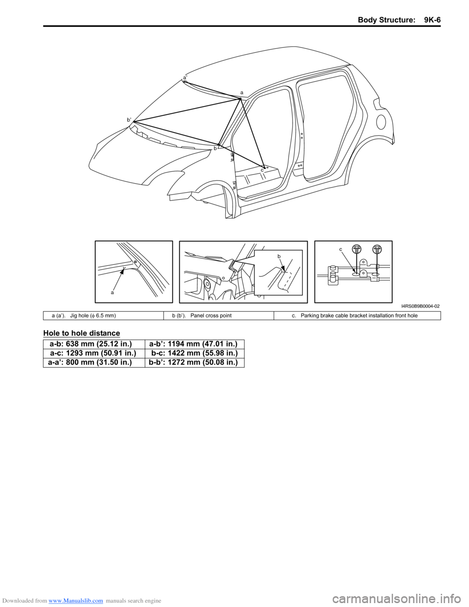
Hole to hole distance
a
cb
a’
a
bc
b’
I4RS0B9B0004-02
a (a’). Jig hole (φ 6.5 mm) b (b’). Panel cross point c. Parking brake cable bracket installation front hole
a-b: 638 mm (25.12 in.) a-b’: 1194 mm (47.01 in.)
a-c: 1293 mm (50.91 in.) b-c: 1422 mm (55.98 in.)
a-a’: 800 mm (31.50 in.) b-b’: 1272 mm (50.08 in.)
Page 1384 of 1496
Downloaded from www.Manualslib.com manuals search engine 9K-7 Body Structure:
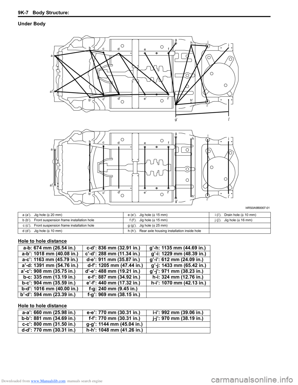
Under Body
Hole to hole distance
Hole to hole distance
ab
c d e fg
h i
j
a' b'c'
d'
e' f'
g' i'
j'
a b
c d e fg
hi
j
a' b'c'
d'
e' f'
g'h'
i' j'
h'
I4RS0A9B0007-01
a (a’). Jig hole (
φ 20 mm) e (e’). Jig hole ( φ 15 mm) i (i’). Drain hole ( φ 10 mm)
b (b’). Front suspension frame installation hole f (f’). Jig hole ( φ 15 mm) j (j’). Jig hole ( φ 16 mm)
c (c’). Front suspension frame installation hole g (g’). Jig hole (φ 25 mm)
d (d’). Jig hole ( φ 10 mm) h (h’). Rear axle housing installation inside hole
a-b: 674 mm (26.54 in.) c-d’: 836 mm (32.91 in.) g’-h: 1135 mm (44.69 in.)
a-b’: 1018 mm (40.08 in.) c’-d’: 288 mm (11.34 in.) g’-i: 1229 mm (48.39 in.) a-c’: 1163 mm (45.79 in.) d-e’: 911 mm (35.87 in.) g’-i’: 612 mm (24.09 in.)
a’-d: 1391 mm (54.76 in.) d-f’: 1205 mm (47.44 in.) g’-j: 1433 mm (65.42 in.)
a’-c’: 908 mm (35.75 in.) d’-e’: 488 mm (1 9.21 in.) g’-j’: 971 mm (38.23 in.)
b-c: 335 mm (13.19 in.) e-f’: 887 mm (34.92 in.) h-i: 324 mm (12.76 in.)
b-c’: 904 mm (35.59 in.) e’-f’: 440 mm (17.32 in.) h-i’: 1070 mm (42.13 in.)
b-d’: 1016 mm (40.00 in.) f-g: 240 mm (9.45 in.)
b’-d’: 594 mm (23.39 in.) f-g’: 969 mm (38.15 in.)
a-a’: 660 mm (25.98 in.) e-e’: 770 mm (30.31 in.) i-i’: 992 mm (39.06 in.)
b-b’: 881 mm (34.69 in.) f-f’: 770 mm (30.31 in.) j-j’: 970 mm (38.19 in.) c-c’: 800 mm (31.50 in.) g-g’: 1144 mm (45.04 in.)
d-d’: 770 mm (30.31 in.) h-h’: 1048 mm (41.26 in.)
Page 1385 of 1496
Downloaded from www.Manualslib.com manuals search engine Body Structure: 9K-8
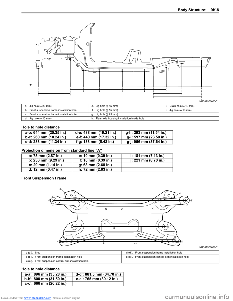
Hole to hole distance
Projection dimension from standard line “A”
Front Suspension Frame
Hole to hole distance
i
g
f
e
d
c
ab
"A"j
h
I4RS0A9B0008-01
a. Jig hole ( φ 20 mm) e. Jig hole ( φ 15 mm) i. Drain hole ( φ 10 mm)
b. Front suspension frame installation hole f. Jig hole (φ 15 mm) j. Jig hole (φ 16 mm)
c. Front suspension frame installation hole g. Jig hole ( φ 25 mm)
d. Jig hole ( φ 10 mm) h. Rear axle housing installation inside hole
a-b: 644 mm (25.35 in.) d-e: 488 mm (19.21 in.) g-h: 293 mm (11.54 in.)
b-c: 260 mm (10.24 in.) e-f: 440 mm (17.32 in.) g-i: 597 mm (23.50 in.)
c-d: 288 mm (11.34 in.) f-g: 138 mm (5.43 in.) g-j: 956 mm (37.64 in.)
a: 73 mm (2.87 in.) e: 10 mm (0.39 in.) i: 181 mm (7.13 in.)
b: 236 mm (9.29 in.) f: 10 mm (0.39 in.) j: 221 mm (8.70 in.) c: 29 mm (1.14 in.) g: 68 mm (2.68 in.)
d: 12 mm (0.47 in.) h: 72 mm (2.83 in.)
a b c
d
e
a'
b'
c' d'
e'
I4RS0A9B0009-01
a (a’). Stud
d (d’). Front suspension frame installation hole
b (b’). Front suspension frame installation hole e (e’). Front suspension control arm installation hole
c (c’). Front suspension control arm installation hole
a-a’: 896 mm (35.28 in.) d-d’: 881.5 mm (34.70 in.)
b-b’: 800 mm (31.50 in.) e-e’: 765 mm (30.12 in.) c-c’: 666 mm (26.22 in.)
Page 1386 of 1496
Downloaded from www.Manualslib.com manuals search engine 9K-9 Body Structure:
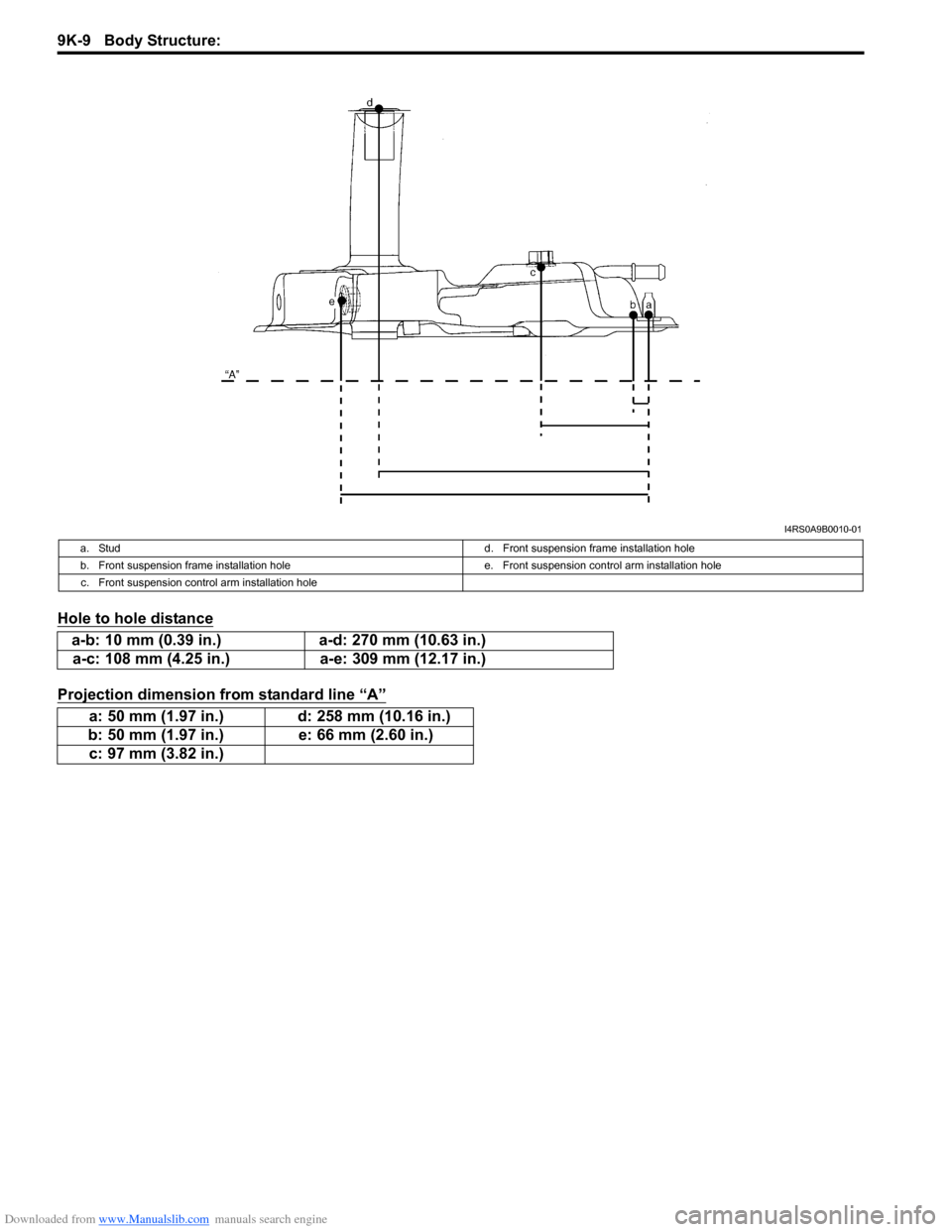
Hole to hole distance
Projection dimension from standard line “A”
I4RS0A9B0010-01
a. Studd. Front suspension frame installation hole
b. Front suspension frame installation hole e. Front suspension control arm installation hole
c. Front suspension control arm installation hole
a-b: 10 mm (0.39 in.) a-d: 270 mm (10.63 in.)
a-c: 108 mm (4.25 in.) a-e: 309 mm (12.17 in.)
a: 50 mm (1.97 in.) d: 258 mm (10.16 in.)
b: 50 mm (1.97 in.) e: 66 mm (2.60 in.)
c: 97 mm (3.82 in.)
Page 1387 of 1496
Downloaded from www.Manualslib.com manuals search engine Body Structure: 9K-10
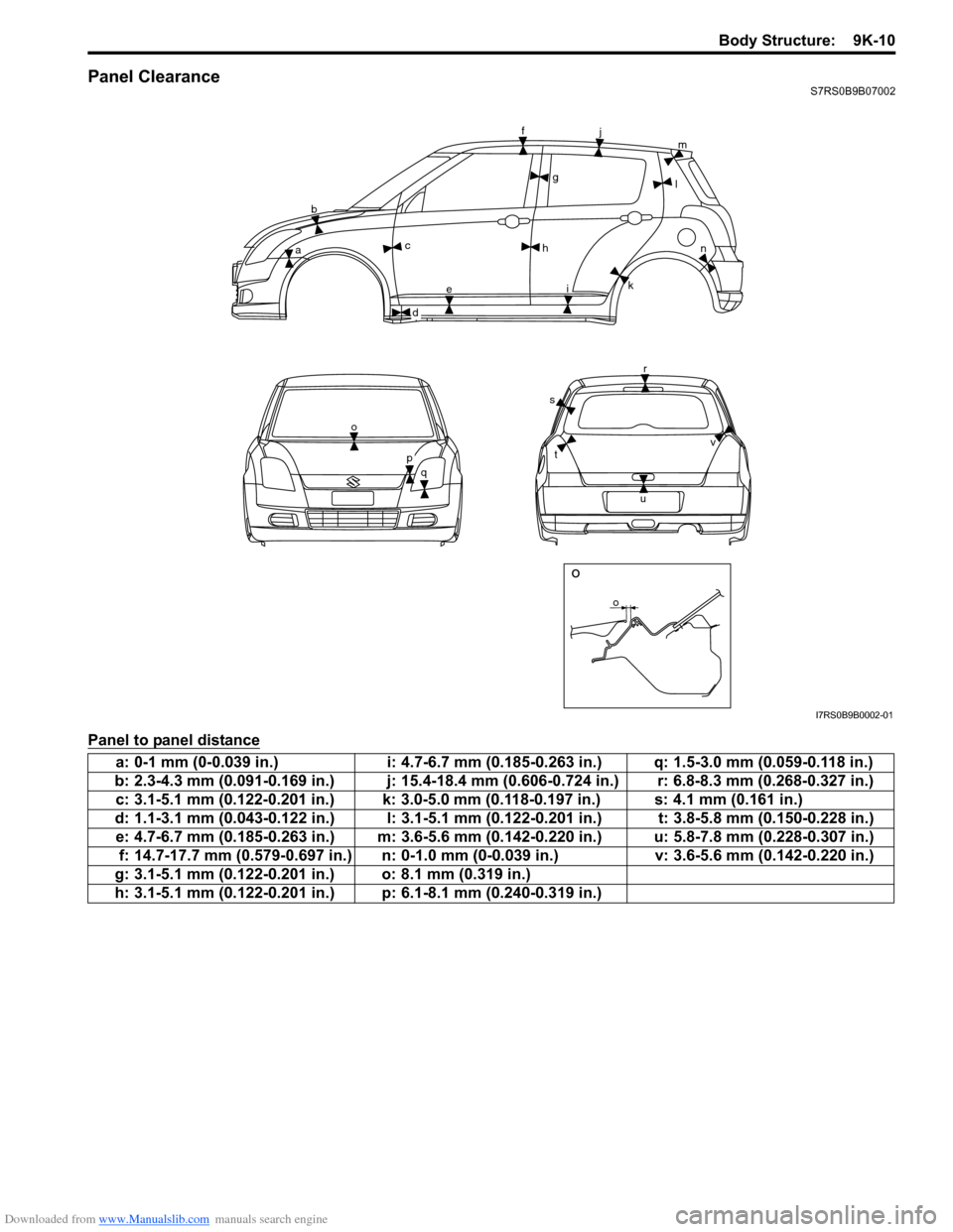
Panel ClearanceS7RS0B9B07002
Panel to panel distance
o
bc
e h
f
j
i l
m
k n
r
u
s
t
o
q
o
g
a
d
p
v
I7RS0B9B0002-01
a: 0-1 mm (0-0.039 in.) i: 4.7-6.7 mm (0.185-0.263 in.) q: 1.5-3.0 mm (0.059-0.118 in.)
b: 2.3-4.3 mm (0.091-0.169 in.) j: 15.4-18.4 mm (0.606-0.724 in.) r: 6.8-8.3 mm (0.268-0.327 in.) c: 3.1-5.1 mm (0.122-0.201 in.) k: 3.0-5.0 mm (0.118-0.197 in.) s: 4.1 mm (0.161 in.)
d: 1.1-3.1 mm (0.043-0.122 in.) l: 3.1-5.1 mm (0.122-0.201 in.) t: 3.8-5.8 mm (0.150-0.228 in.) e: 4.7-6.7 mm (0.185-0.263 in.) m: 3.6-5.6 mm (0.142-0.220 in.) u: 5.8-7.8 mm (0.228-0.307 in.) f: 14.7-17.7 mm (0.579-0.697 in.) n: 0-1.0 mm (0-0.039 in.) v: 3.6-5.6 mm (0.142-0.220 in.)
g: 3.1-5.1 mm (0.122-0.201 in.) o: 8.1 mm (0.319 in.)
h: 3.1-5.1 mm (0.122-0.201 in.) p: 6.1-8.1 mm (0.240-0.319 in.)
Page 1388 of 1496
Downloaded from www.Manualslib.com manuals search engine 9L-1 Paint / Coatings:
Body, Cab and Accessories
Paint / Coatings
General Description
Anti-Corrosion Treatment ConstructionS7RS0B9C01001
WARNING!
Standard shop practices, particularly eye protection, should be followed during the performance of the
following operations to avoid personal injury.
As rust proof treatment, steel sheets are given corrosion resistance on the interior and/or exterior.
These corrosion resistance steel sheet materials ar e called one of two-side galvanized steel sheets.
It is for the sake of rust protection that these materials are selected and given a variety of treatments as described
blow.
• Steel sheets are treated with cathodic electro primer which is excellent in corrosion resistance.
• Rust proof wax coatings are applied to door and side sill insides where mois ture is liable to stay.
• Vinyl coating is applied to body underside and wheel housing inside.
• Sealer is applied to door hem, engine compartment steel sheet-to-steel sheet joint, and the like portions to prevent water penetration and resulting in rust occurrence.
In panel replacement or collision damage repair, leaving the relevant area untreated as it is in any operation which
does disturb the rust proof treatment will cause corrosion to th at area. Therefore, it is the essential function of any
repair operation to correctly recoat t he related surfaces of the relevant area.
All the metal panels are coated with metal conditioners an d primer coating during vehicle production. Following the
repair and/or replacement parts installation, every access ible bare metal surface should be cleaned and coated with
rust proof primer. Perform this operation prior to the application of sealer and rust proof wax coating.
Sealer is applied to the spec ific joints of a vehicle during production. The sealer is intended to prevent dust from
entering the vehicle and serves also as an anti corrosion barrier. The sealer is applied to the door and hood hem areas
and between panels. Correct and reseal the originally sealed joints if damaged. Reseal the attaching joints of a new
replacement panel and reseal the hem area of a replacement door or hood.
Use a quality sealer to seal the flanged joints, overlap joints and seams. The sealer must have flexible characteristics
and paint ability after it’s applied to repair areas.
For the sealer to fill open joints, use caulking material. Select a sealer in conf ormance with the place and purpose of a
specific use. Observe the ma nufacturer’s label-stand instructions when using the sealer.
In many cases, repaired places require color painting. When this is required, follow the ordinary techniques specified
for the finish preparation, color painting and undercoating build-up.
Rust proof wax, a penetrative compound, is applied to the metal-to-metal surfaces (door and side sill insides) where it
is difficult to use ordinary undercoating material for coating. Therefore, when selecting the rust proof wax, it may be the
penetrative type.
During the undercoating (vinyl coating) application, care should be taken that sealer is not applied to the engine-
related parts and shock absorber mounting or rotating parts. Following the under coating, make sure that body drain
holes are kept open.
The sequence of the application steps of the anti-corrosion materials are as follows:
1) Clean and prepare the metal surface.
2) Apply primer.
3) Apply sealer (all joints sealed originally).
4) Apply color in areas where color is required such as hem flanges, exposed joints and under body components.
5) Apply anti corrosion compound (penetrative wax).
6) Apply undercoating (rust proof material).
Page 1398 of 1496
![SUZUKI SWIFT 2006 2.G Service Workshop Manual Downloaded from www.Manualslib.com manuals search engine 9M-1 Exterior Trim:
Body, Cab and Accessories
Exterior Trim
Repair Instructions
Roof Molding ComponentsS7RS0B9D06001
42
2
1
3
[A]
2
53 mm (2.0 SUZUKI SWIFT 2006 2.G Service Workshop Manual Downloaded from www.Manualslib.com manuals search engine 9M-1 Exterior Trim:
Body, Cab and Accessories
Exterior Trim
Repair Instructions
Roof Molding ComponentsS7RS0B9D06001
42
2
1
3
[A]
2
53 mm (2.0](/manual-img/20/7607/w960_7607-1397.png)
Downloaded from www.Manualslib.com manuals search engine 9M-1 Exterior Trim:
Body, Cab and Accessories
Exterior Trim
Repair Instructions
Roof Molding ComponentsS7RS0B9D06001
42
2
1
3
[A]
2
53 mm (2.09 in.)
I6RS0C9D0001-01
[A]: Roof side weather-strip installation position
3. Roof molding clip (Push-in type)
: Install roof molding clip to specified position on body with epoxy adhesive applied.
1. Roof molding 4. Windshield side garnish
2. Roof side weather-strip
Page 1401 of 1496
Downloaded from www.Manualslib.com manuals search engine Table of Contents 10- i
10
Section 10
CONTENTS
Control Systems
Precautions ............................................... 10-1
Precautions........................................................... 10-1
Precautions for Control Systems......................... 10-1
Body Electrical Contro l System ........... 10B-1
Precautions......................................................... 10B-1
Precautions in Diagnosing Trouble ................... 10B-1
General Description ........................................... 10B-1 BCM General Description ................................. 10B-1
CAN Communication System Description......... 10B-2
Theft Deterrent Light ......................................... 10B-3
Security Alarm Description (If Equipped) .......... 10B-3
Schematic and Routing Diagram ...................... 10B-4 Body Electrical Control System Wiring Circuit Diagram .......................................................... 10B-4
Connector Layout Diagram of BCM and Junction Block Assembly ................................ 10B-7
Component Locatio n ......................................... 10B-8
BCM and Related System Component Location .......................................................... 10B-8
Diagnostic Information an d Procedures .......... 10B-9
BCM Self-Diagnosis Function ........................... 10B-9
Body Electrical Control System Check............ 10B-10
Scan Tool Data ............................................... 10B-12
DTC Table ....................................................... 10B-14
DTC Check ..................................................... 10B-14
DTC Clearance ............................................... 10B-15
BCM Power Circuit and Ground Circuit Check 10B-16
DTC B1133 (DTC No. 1133): Battery Voltage Too High ....................................................... 10B-17
DTC B1141 / DTC B1142 (No. 1141 / No. 1142): Outside Air Temperature (Ambient
Temp.) Sensor Circuit Ma lfunction ................ 10B-18
DTC B1150 (No. 1150): Air Bag Communication Circuit Malfunction .............. 10B-19
DTC B1157 (No. 1157): Air Bag Deployment Signal Input ................................................... 10B-20
DTC B1170 (No. 1170 ): EEPROM Access
Error .............................................................. 10B-21
DTC U0155 (No. 0155): Lost Communication with Instrument Panel Cluster (IPC) Control
Module .......................................................... 10B-21
DTC U1073 (No. 1073): Control Module Communication Bus Off ................................ 10B-24 DTC U1100 (No. 1100): Lost Communication
with ECM ....................................................... 10B-25
DTC U1101 (No. 1101): Lost Communication with TCM ....................................................... 10B-27
DTC U1144 (No. 1144): Lost Communication with Keyless Start Control Module ................ 10B-29
Inspection of BCM and its Circuits .................. 10B-31
Repair Instructions ........... ...............................10B-39
BCM (Included in Junction Block Assembly) Removal and Installation ............................... 10B-39
Outside Air Temperature Sensor Removal and Installation .............................................. 10B-39
Outside Air Temperature Sensor Inspection ... 10B-39
Security Alarm Mode Selection Procedure (If Equipped) ...................................................... 10B-39
Special Tools and Equipmen t .........................10B-40
Special Tool .................................................... 10B-40
Immobilizer Control Syst em ................. 10C-1
Precautions.........................................................10C-1
Precautions in Diagnosing Troubles .................10C-1
Precaution in Replacing ECM ...........................10C-1
Precautions in Handli ng Immobilizer Control
System ............................................................10C-1
General Description ...........................................10C-2 Immobilizer Control System Introduction ..........10C-2
Immobilizer Control System Components Location...........................................................10C-3
On-Board Diagnostic System Description (Self-diagnosis Function) ................................10C-3
Schematic and Routing Diag ram ......................10C-4
Immobilizer Control System Wiring Circuit Diagram...........................................................10C-4
Diagnostic Information an d Procedures ..........10C-5
Immobilizer Control System Check ...................10C-5
Diagnostic Trouble Code (DTC) Check.............10C-5
Diagnostic Trouble Code (DTC) Clearance ......10C-6
Diagnostic Trouble Code (DTC) Table ..............10C-6
Scan Tool Data .................................................10C-7
Immobilizer Indicator Lamp Does Not Come ON with Ignition Switch ON and Engine Stop ..10C-7
Immobilizer Indicator Lamp Remains ON after Engine Starts...................................................10C-8
DTC P1614: Transponder Re sponse Error .......10C-9