2006 SUZUKI SWIFT wheel nuts
[x] Cancel search: wheel nutsPage 529 of 1496

Downloaded from www.Manualslib.com manuals search engine Rear Brakes: 4C-5
4) Pass parking brake cable (1) through bracket (3) of caliper.
5) Hang parking brake cable on lever (2) as follows.
NOTE
Make sure that lever (4) contacts pin (5).
6) Install brake pads and caliper referring to “Rear Disc Brake Pad Removal and Installation”.
7) Connect flexible hose (1) with new washers to caliper (2).
WARNING!
Make sure that flexible hose is not twisted
when tightening joint bolt. If it is twisted,
reconnect it using care not to twist it.
Tightening torque
Flexible hose joint bolt (a): 23 N·m (2.3 kgf-m,
17.0 lb-ft) 8) Install brake cable clip (1) securely to bracket (2).
9) After reassembling brake lines, bleed air from them
referring to “Air Bleeding of Brake System in Section
4A”.
10) Check to make sure that system is free from fluid
leakage.
11) Start engine and then depress brake pedal with about 300 N (30 kg, 66 lbs) load 3 times or more so
as to obtain proper disc to pad clearance.
12) Check to make sure that parking brake lever stroke is as specified. Refer to “Parking Brake Inspection
and Adjustment in Section 4D”.
13) Tighten wheel nuts to specified torque.
Tightening torque
Wheel bolt: 85 N·m (8.5 kgf-m, 61.5 lb-ft)
14) Remove vehicle from hoist and perform brake test (foot brake and parking brake).
1
23
45
I6RS0C430010-01
1 (a)2
I6RS0C430011-01
1
2
I6RS0C430012-01
Page 533 of 1496
Downloaded from www.Manualslib.com manuals search engine Rear Brakes: 4C-9
Rear Brake Disc Removal and InstallationS7RS0B4306008
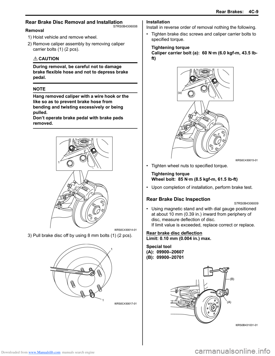
Removal1) Hoist vehicle and remove wheel.
2) Remove caliper assembly by removing caliper
carrier bolts (1) (2 pcs).
CAUTION!
During removal, be ca reful not to damage
brake flexible hose and not to depress brake
pedal.
NOTE
Hang removed caliper with a wire hook or the
like so as to prevent brake hose from
bending and twisting excessively or being
pulled.
Don’t operate brake pedal with brake pads
removed.
3) Pull brake disc off by using 8 mm bolts (1) (2 pcs). Installation
Install in reverse order of removal nothing the following.
• Tighten brake disc screws and caliper carrier bolts to
specified torque.
Tightening torque
Caliper carrier bolt (a): 60 N·m (6.0 kgf-m, 43.5 lb-
ft)
• Tighten wheel nuts to specified torque. Tightening torque
Wheel bolt: 85 N·m (8.5 kgf-m, 61.5 lb-ft)
• Upon completion of installation, perform brake test.
Rear Brake Disc InspectionS7RS0B4306009
• Using magnetic stand and with dial gauge positioned at about 10 mm (0.39 in.) inward from periphery of
disc, measure deflection of disc.
If limit value is exceeded, replace correct or replace.
Rear brake disc deflection
Limit: 0.10 mm (0.004 in.) max.
Special tool
(A): 09900–20607
(B): 09900–20701
1
I6RS0C430014-01
1 1I6RS0C430017-01
(a)
I6RS0C430015-01
(B)
(A)
I6RS0B431031-01
Page 538 of 1496
Downloaded from www.Manualslib.com manuals search engine 4D-3 Parking Brake:
6) Release parking brake lever and then make sure that there is no drag in rear wheel.
If there is, repeats go to step 2).
7) Make sure that the number of notch is between 4 and 9 when operating parking brake lever.
8) If the number of notch is not between 4 and 9, replace parking brake cable and/or inspect rear
brake caliper.
Parking brake stroke
When lever is pulled up at 200 N (20kg, 44lbs) : 4
to 9 notches
Parking Brake Cable Removal and InstallationS7RS0B4406002
Removal
NOTE
When it is necessary to remove both right
and left parking brake cables, repeat below
steps 2) and 5) on right and left wheels.
1) Hoist vehicle.
2) Remove wheel.
3) Disconnect parking brake cable from equalizer (parking brake lever) and clamps.
4) Disconnect parking brake cable from lever referring to “Rear Disc Brake Caliper Removal and Installation
in Section 4C”.
5) Remove parking brake cable and parking cable bracket.
Installation
Install it by reversing removal procedure, noting the
following points.
• Install clamps properly referring to “Parking Brake Cable Construction”.
• Tighten bolts and nuts to specified torque referring to “Parking Brake Cable Construction”.
Tightening torque
Parking brake lever bolt: 25 N·m (2.5 kgf-m, 18.0
lb-ft)
Parking cable clamp bolt: 11 N·m (1.1 kgf-m, 8.0
lb-ft)
Parking cable bracket bolt: 25 N·m (2.5 kgf-m,
18.0 lb-ft)
• Adjust parking brake cable. Refer to “Parking Brake Inspection and Adjustment”.
• Check brake disc for dragging and brake system for proper performance. Brake test should be performed.
Parking Brake Lever Removal and InstallationS7RS0B4406003
Removal
1) Remove console box.
2) Block vehicle wheels and release parking brake lever.
3) Disconnect lead wire of parking brake switch at coupler.
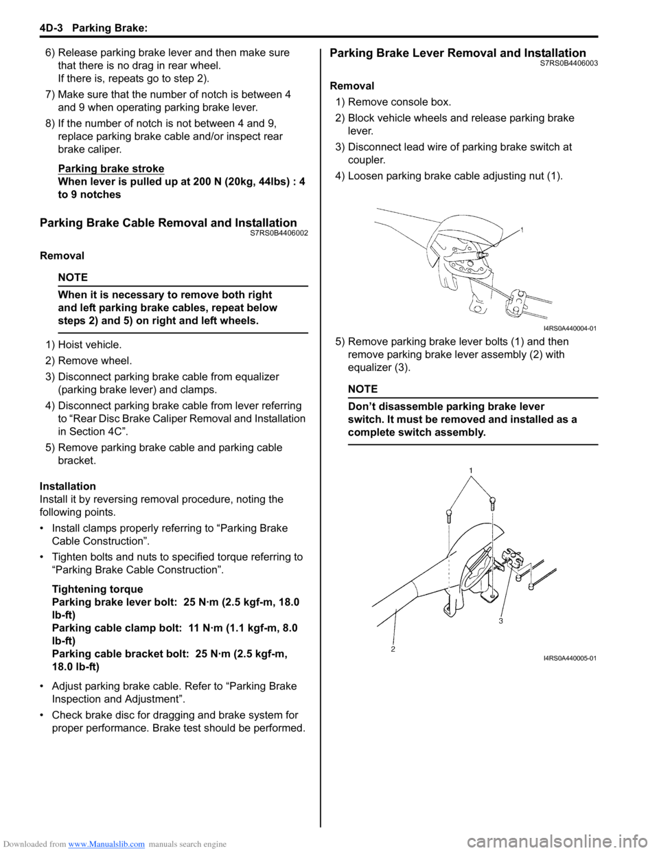
4) Loosen parking brake cable adjusting nut (1).
5) Remove parking brake lever bolts (1) and then remove parking brake lever assembly (2) with
equalizer (3).
NOTE
Don’t disassemble parking brake lever
switch. It must be removed and installed as a
complete switch assembly.
I4RS0A440004-01
I4RS0A440005-01
Page 872 of 1496
Downloaded from www.Manualslib.com manuals search engine 6B-1 Steering Wheel and Column:
Steeri ng
Steering Wheel and Column
Precautions
Service Precautions of Steering Wheel and
Column
S7RS0B6200001
For service precautions, refer to “Precautions on Service
and Diagnosis of Air Bag System in Section 8B”.
Service and Diagnosis
For diagnosis and servicing, refer to “Precautions on
Service and Diagnosis of Air Bag System in Section 8B”.
Disabling Air Bag System
For disabling air bag system, refer to “Disabling Air Bag
System in Section 8B”. Enabling Air Bag System
For enabling air bag system, refer to “Enabling Air Bag
System in Section 8B”.
Handling and Storage
For handling and storage, refer to “Precautions on
Handling and Storage of Air Bag System Components in
Section 8B”.
Disposal
For disposal, refer to “Prec
autions on Disposal of Air
Bag and Seat Belt Pretensioner in Section 8B”.
General Description
Steering Wheel and Column ConstructionS7RS0B6201001
This double tube type steering column has the following three important features in addition to the steering function:
• The column is energy absorbing, desig ned to compress in a front-end collision.
• The ignition switch and lock are mounted conveniently on this column.
• With the column mounted lock, the ignition and steering op erations can be locked to inhibit theft of the vehicle.
To insure the energy absorbing action, it is important th at only the specified screws, bolts and nuts be used as
designated, and that they are tightened to the specified torque. When the column assembly is removed from the
vehicle, special care must be taken in handling it. Use of a steering wheel puller or a sharp blow on the end of the
steering shaft, leaning on the assembly, or dropping the a ssembly could shear the plastic shear pins which maintain
column length and position.
The driver air bag (inflator) module is one of the supplemental restraint (air bag) system components and is mounted
to the center of the steering wheel. During certain frontal crashes, the air bag system supplements the restraint of the
driver’s and passenger’s seat belts by deploying the air b ags. The air bag (inflator) module should be handled with
care to prevent accidental deployment. When servicing, be sure to observe “Precautions on Service and Diagnosis of
Air Bag System in Section 8B”.
Page 878 of 1496
Downloaded from www.Manualslib.com manuals search engine 6B-7 Steering Wheel and Column:
Steering Column Removal and InstallationS7RS0B6206006
CAUTION!
Once the steering column is removed from
the vehicle, the column is extremely
susceptible to damage.
• Dropping the column assembly on its end could collapse the steering shaft or loosen
the plastic shear pins which maintain
column length.
• Leaning on the column assembly could cause it to bend or deform.
Any of the damage could impair the column’s
collapsible design.
Steering column mounting nuts should not
be loosened with steering shaft joint upper
side bolt tightened as this could cause
damage to shaft joint bearing.
NOTE
When servicing steering column or any
column-mounted component, remove
steering wheel. But when removing steering
column simply to gain access to instrument
panel components, leave steering wheel
installed on steering column.
Removal
WARNING!
Never rest a steering column assembly on
the steering wheel with the air bag (inflator)
module face down and column vertical.
Otherwise, personal injury may result.
1) Disconnect negative (–) cable at battery.
2) Disable air bag system. Re fer to “Disabling Air Bag
System in Section 8B”.
3) Remove steering wheel and contact coil cable assembly referring to “S teering Wheel Removal and
Installation” and “Contact Coil Cable Assembly
Removal and Installation”.
4) Detach lighting switch and wiper switch from steering column.
5) Remove immobilizer cont rol module from steering
column, referring to “Immo bilizer Control Module
(ICM) Removal and Installation in Section 10C”.
6) Remove steering column hole cover.
7) Remove steering joint cover.
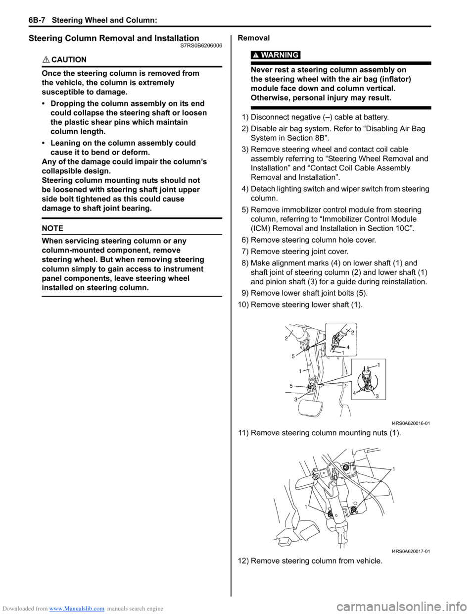
8) Make alignment marks (4) on lower shaft (1) and shaft joint of steering column (2) and lower shaft (1)
and pinion shaft (3) for a guide during reinstallation.
9) Remove lower shaf t joint bolts (5).
10) Remove steering lower shaft (1).
11) Remove steering column mounting nuts (1).
12) Remove steering column from vehicle.
I4RS0A620016-01
1
1
I4RS0A620017-01
Page 879 of 1496
Downloaded from www.Manualslib.com manuals search engine Steering Wheel and Column: 6B-8
Installation
CAUTION!
After tightening steering column mounting
nuts, shaft joint bolts should be tightened.
Wrong tightening order could cause a
damage to shaft joint.
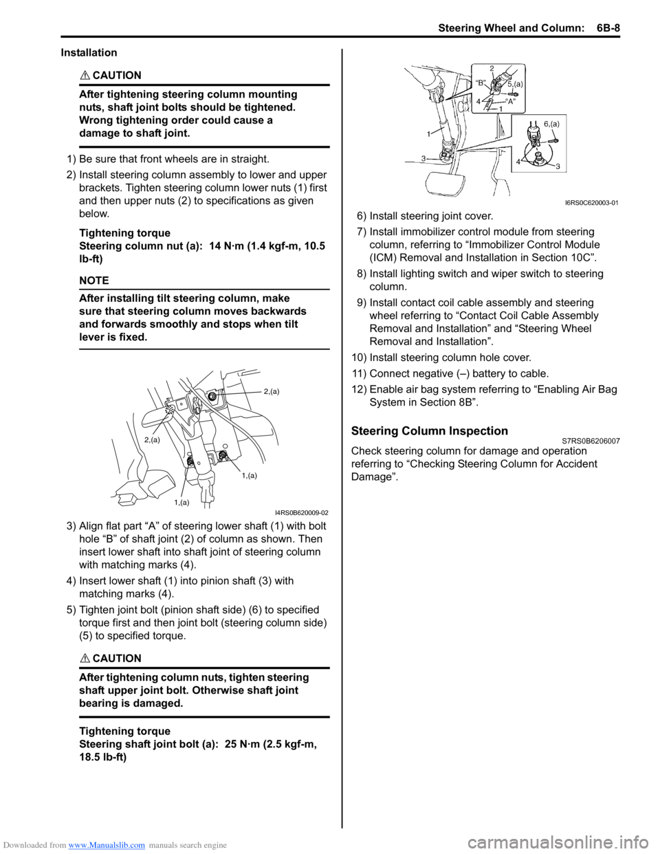
1) Be sure that front wheels are in straight.
2) Install steering column assembly to lower and upper brackets. Tighten steering column lower nuts (1) first
and then upper nuts (2) to specifications as given
below.
Tightening torque
Steering column nut (a): 14 N·m (1.4 kgf-m, 10.5
lb-ft)
NOTE
After installing tilt steering column, make
sure that steering column moves backwards
and forwards smoothly and stops when tilt
lever is fixed.
3) Align flat part “A” of stee ring lower shaft (1) with bolt
hole “B” of shaft joint (2) of column as shown. Then
insert lower shaft into shaf t joint of steering column
with matching marks (4).
4) Insert lower shaft (1) into pinion shaft (3) with matching marks (4).
5) Tighten joint bolt (pinion shaft side) (6) to specified torque first and then joint bolt (steering column side)
(5) to specified torque.
CAUTION!
After tightening column nuts, tighten steering
shaft upper joint bolt. Otherwise shaft joint
bearing is damaged.
Tightening torque
Steering shaft joint bolt (a): 25 N·m (2.5 kgf-m,
18.5 lb-ft) 6) Install steering joint cover.
7) Install immobilizer cont
rol module from steering
column, referring to “Immo bilizer Control Module
(ICM) Removal and Installation in Section 10C”.
8) Install lighting switch and wiper switch to steering column.
9) Install contact coil cable assembly and steering wheel referring to “Conta ct Coil Cable Assembly
Removal and Installation” and “Steering Wheel
Removal and Installation”.
10) Install steering column hole cover. 11) Connect negative (–) battery to cable.
12) Enable air bag system refe rring to “Enabling Air Bag
System in Section 8B”.
Steering Column InspectionS7RS0B6206007
Check steering column for damage and operation
referring to “Checking Steering Column for Accident
Damage”.
2,(a)
1,(a)
1,(a)
2,(a)
I4RS0B620009-02
I6RS0C620003-01
Page 924 of 1496
Downloaded from www.Manualslib.com manuals search engine 6C-42 Power Assisted Steering System:
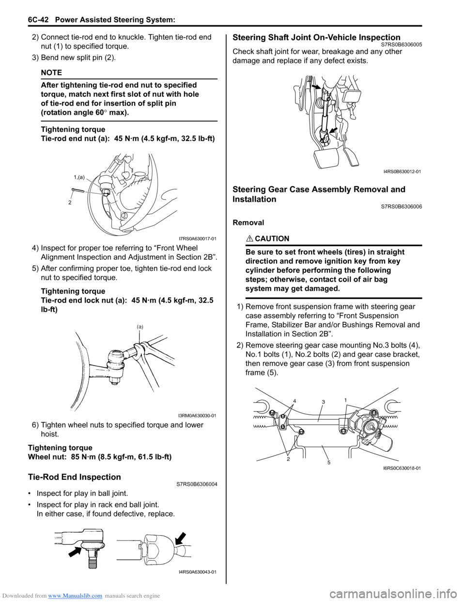
2) Connect tie-rod end to knuckle. Tighten tie-rod end nut (1) to spec ified torque.
3) Bend new split pin (2).
NOTE
After tightening tie-rod end nut to specified
torque, match next first slot of nut with hole
of tie-rod end for insertion of split pin
(rotation angle 60 ° max).
Tightening torque
Tie-rod end nut (a): 45 N·m (4.5 kgf-m, 32.5 lb-ft)
4) Inspect for proper toe re ferring to “Front Wheel
Alignment Inspection and Adjustment in Section 2B”.
5) After confirming proper toe, tighten tie-rod end lock nut to specified torque.
Tightening torque
Tie-rod end lock nut (a): 45 N·m (4.5 kgf-m, 32.5
lb-ft)
6) Tighten wheel nuts to specified torque and lower hoist.
Tightening torque
Wheel nut: 85 N·m (8.5 kgf-m, 61.5 lb-ft)
Tie-Rod End InspectionS7RS0B6306004
• Inspect for play in ball joint.
• Inspect for play in rack end ball joint. In either case, if found defective, replace.
Steering Shaft Joint On-Vehicle InspectionS7RS0B6306005
Check shaft joint for wear, breakage and any other
damage and replace if any defect exists.
Steering Gear Case Assembly Removal and
Installation
S7RS0B6306006
Removal
CAUTION!
Be sure to set front wheels (tires) in straight
direction and remove ignition key from key
cylinder before performing the following
steps; otherwise, contact coil of air bag
system may get damaged.
1) Remove front suspension frame with steering gear case assembly referrin g to “Front Suspension
Frame, Stabilizer Bar and/ or Bushings Removal and
Installation in Section 2B”.
2) Remove steering gear case mounting No.3 bolts (4), No.1 bolts (1), No.2 bolts (2) and gear case bracket,
then remove gear case (3) from front suspension
frame (5).
2 1,(a)
I7RS0A630017-01
I3RM0A630030-01
I4RS0A630043-01
I4RS0B630012-01
25
3
14
I6RS0C630018-01
Page 1313 of 1496
Downloaded from www.Manualslib.com manuals search engine Instrumentation / Driver Info. / Horn: 9C-18
Instrument Panel Removal and InstallationS7RS0B9306015
WARNING!
Refer to “Air Bag Warning in Section 00”
before starting service work.
Removal
1) Disconnect negative (–) cable at battery.
2) Disable air bag system referring to “Disabling Air Bag System in Section 8B”.
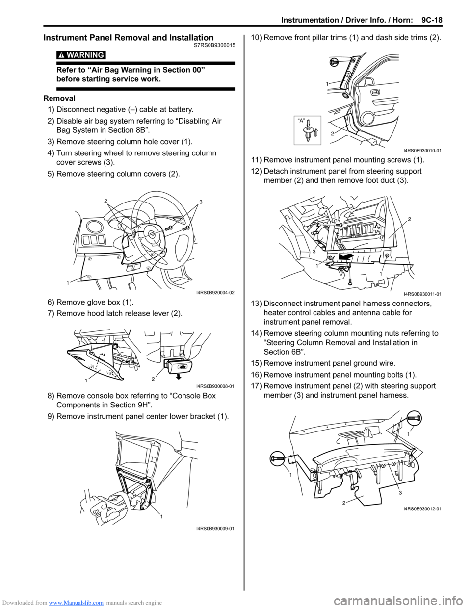
3) Remove steering column hole cover (1).
4) Turn steering wheel to remove steering column cover screws (3).
5) Remove steering column covers (2).
6) Remove glove box (1).
7) Remove hood latch release lever (2).
8) Remove console box referring to “Console Box Components in Section 9H”.
9) Remove instrument panel center lower bracket (1). 10) Remove front pillar trims
(1) and dash side trims (2).
11) Remove instrument panel mounting screws (1).
12) Detach instrument panel from steering support member (2) and then remove foot duct (3).
13) Disconnect instrument panel harness connectors, heater control cables and antenna cable for
instrument panel removal.
14) Remove steering column mounting nuts referring to “Steering Column Remova l and Installation in
Section 6B”.
15) Remove instrument panel ground wire.
16) Remove instrument panel mounting bolts (1).
17) Remove instrument panel (2) with steering support member (3) and instrument panel harness.
1
32
I4RS0B920004-02
2
1I4RS0B930008-01
1
I4RS0B930009-01
“A”
“A”
1
2
I4RS0B930010-01
1
1 2
3
I4RS0B930011-01
1 1
2
3I4RS0B930012-01