2006 SUZUKI SWIFT eco
[x] Cancel search: ecoPage 1366 of 1496
Downloaded from www.Manualslib.com manuals search engine 9G-4 Seats:
Rear Seat Removal and InstallationS7RS0B9706004
Removal1) Fold rear seat back forward.
2) Remove seat mounting bolts and nuts to remove seat assembly.
3) Disassemble and repair seat as necessary.
Installation
Reverse removal procedure to install rear seat.
• Tighten seat back striker mounting bolts according to “Rear Seat Components”.
• Torque to specifications in “Rear Seat Components”.
• When installing seat cushion, align seat cushion hook with center hinge bracket.
Specifications
Tightening Torque SpecificationsS7RS0B9707001
NOTE
The specified tightening torque is also described in the following.
“Front Seat Components”
“Rear Seat Components”
Reference:
For the tightening torque of fastener not specified in this section, refer to “Fasteners Information in Section 0A”.
Special Tools and Equipment
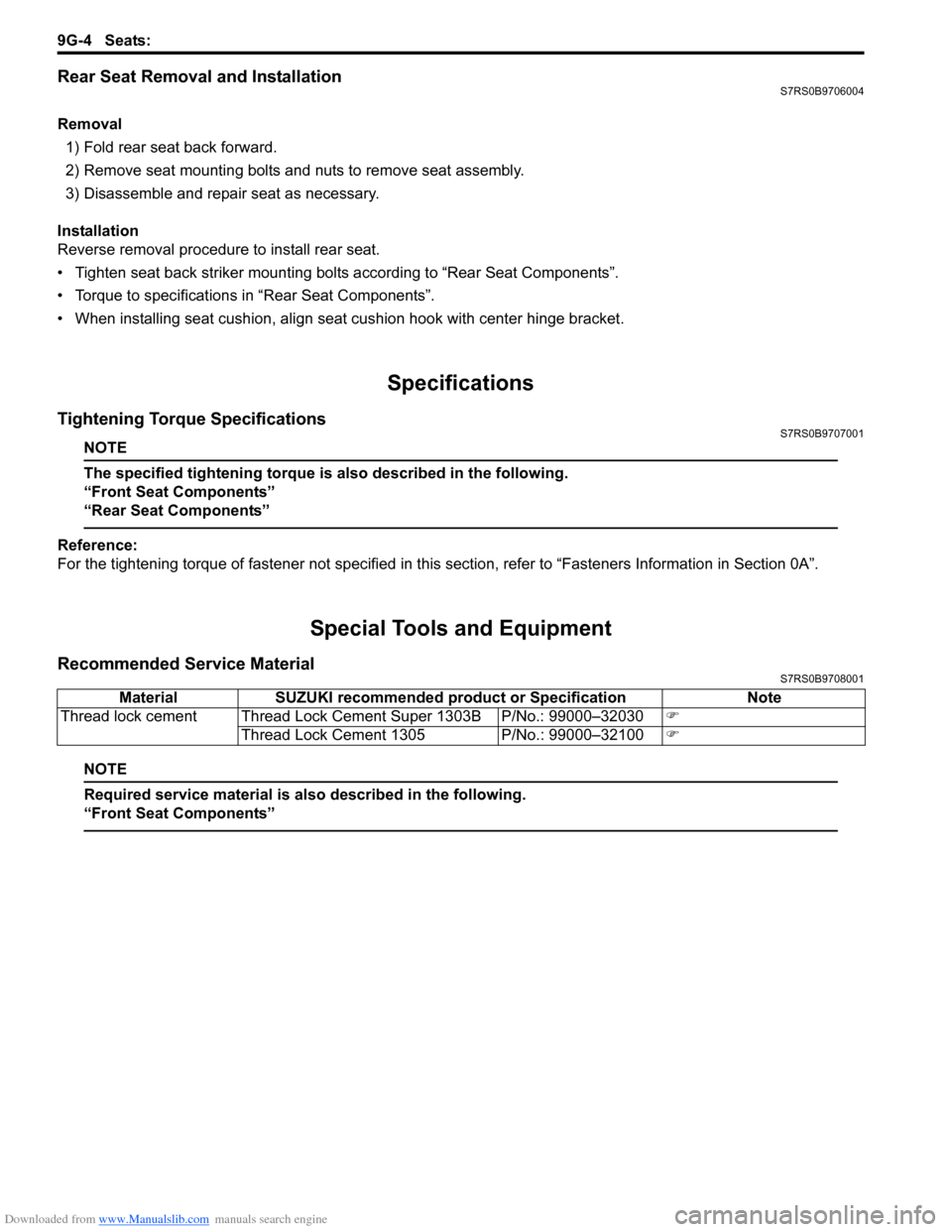
Recommended Service MaterialS7RS0B9708001
NOTE
Required service material is also described in the following.
“Front Seat Components”
Material SUZUKI recommended product or Specification Note
Thread lock cement Thread Lock Cement Super 1303B P/No.: 99000–32030 �)
Thread Lock Cement 1305 P/No.: 99000–32100 �)
Page 1370 of 1496
Downloaded from www.Manualslib.com manuals search engine 9J-1 Hood / Fenders / Doors:
Body, Cab and Accessories
Hood / Fenders / Doors
Repair Instructions
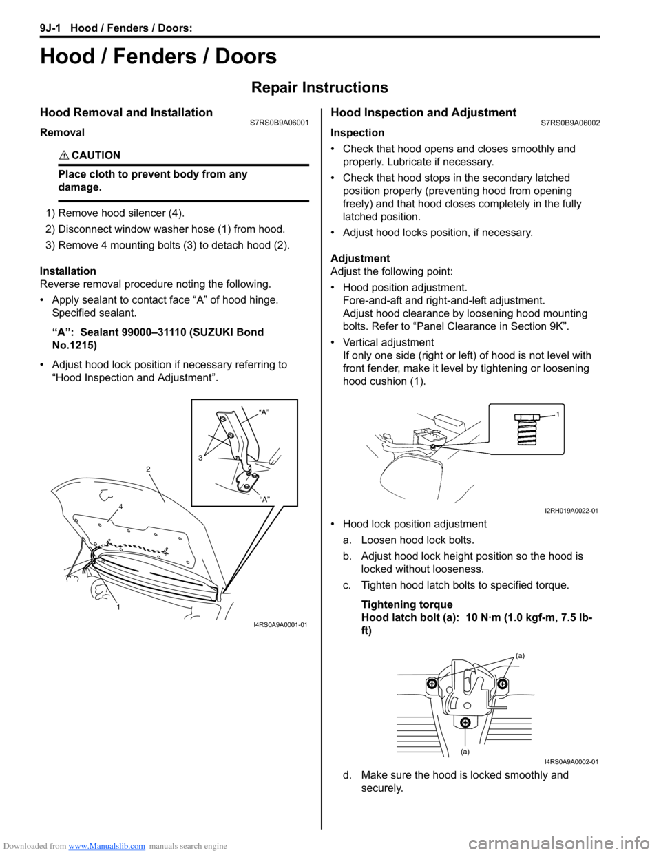
Hood Removal and InstallationS7RS0B9A06001
Removal
CAUTION!
Place cloth to prevent body from any
damage.
1) Remove hood silencer (4).
2) Disconnect window washer hose (1) from hood.
3) Remove 4 mounting bolts (3) to detach hood (2).
Installation
Reverse removal procedure noting the following.
• Apply sealant to contact face “A” of hood hinge. Specified sealant.
“A”: Sealant 99000–31110 (SUZUKI Bond
No.1215)
• Adjust hood lock position if necessary referring to “Hood Inspection and Adjustment”.
Hood Inspection and AdjustmentS7RS0B9A06002
Inspection
• Check that hood opens and closes smoothly and properly. Lubricate if necessary.
• Check that hood stops in the secondary latched position properly (preventing hood from opening
freely) and that hood closes completely in the fully
latched position.
• Adjust hood locks position, if necessary.
Adjustment
Adjust the following point:
• Hood position adjustment. Fore-and-aft and right-and-left adjustment.
Adjust hood clearance by loosening hood mounting
bolts. Refer to “Panel Clearance in Section 9K”.
• Vertical adjustment If only one side (right or left) of hood is not level with
front fender, make it level by tightening or loosening
hood cushion (1).
• Hood lock position adjustment a. Loosen hood lock bolts.
b. Adjust hood lock height position so the hood is locked without looseness.
c. Tighten hood latch bolts to specified torque.
Tightening torque
Hood latch bolt (a): 10 N·m (1.0 kgf-m, 7.5 lb-
ft)
d. Make sure the hood is locked smoothly and securely.
“A”
“A”
3
2
4
1
I4RS0A9A0001-01
I2RH019A0022-01
(a)
(a)I4RS0A9A0002-01
Page 1373 of 1496
Downloaded from www.Manualslib.com manuals search engine Hood / Fenders / Doors: 9J-4
Installation
Reverse removal procedure to install door assembly
noting the following instructions.
• When replacing door, coat replacement door inside with wax for proper anti-cor rosion treatment. Refer to
“Sealant Application Areas in Section 9L”.
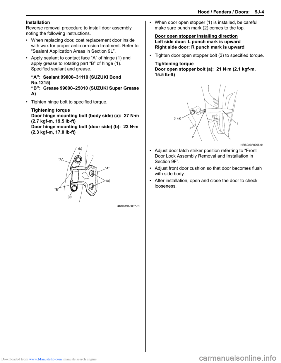
• Apply sealant to contact face “A” of hinge (1) and apply grease to rotating part “B” of hinge (1).
Specified sealant and grease.
“A”: Sealant 99000–31110 (SUZUKI Bond
No.1215)
“B”: Grease 99000–25010 (SUZUKI Super Grease
A)
• Tighten hinge bolt to specified torque. Tightening torque
Door hinge mounting bolt (body side) (a): 27 N·m
(2.7 kgf-m, 19.5 lb-ft)
Door hinge mounting bolt (door side) (b): 23 N·m
(2.3 kgf-m, 17.0 lb-ft) • When door open stopper (1) is installed, be careful
make sure punch mark (2) comes to the top.
Door open stopper installing direction
Left side door: L punch mark is upward
Right side door: R punch mark is upward
• Tighten door open stopper bolt (3) to specified torque. Tightening torque
Door open stopper bolt (a): 21 N·m (2.1 kgf-m,
15.5 lb-ft)
• Adjust door latch striker position referring to “Front Door Lock Assembly Removal and Installation in
Section 9F”.
• Adjust front door cushion so that door becomes flush with side body.
• After installation, open and close the door to check looseness.
I4RS0A9A0007-01
I4RS0A9A0008-01
Page 1377 of 1496
Downloaded from www.Manualslib.com manuals search engine Hood / Fenders / Doors: 9J-8
Specifications
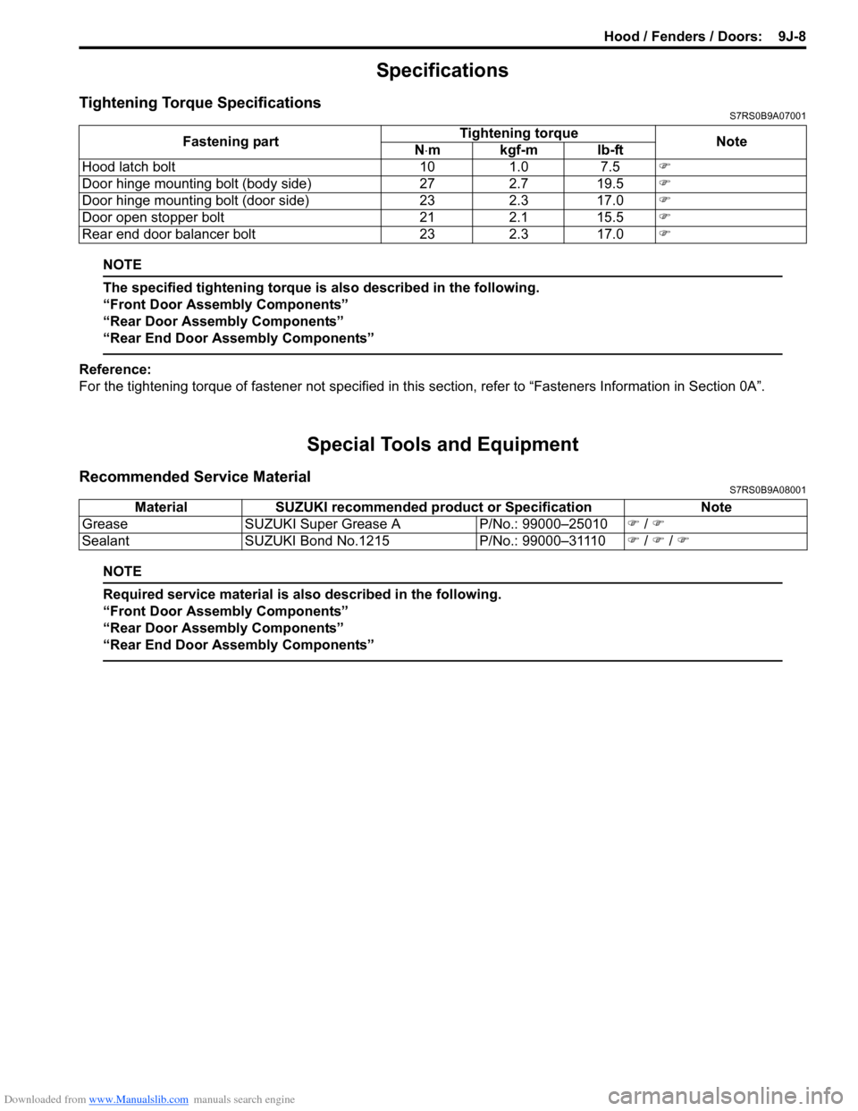
Tightening Torque SpecificationsS7RS0B9A07001
NOTE
The specified tightening torque is also described in the following.
“Front Door Assembly Components”
“Rear Door Assembly Components”
“Rear End Door Assembly Components”
Reference:
For the tightening torque of fastener not specified in this section, refer to “Fasteners Information in Section 0A”.
Special Tools and Equipment
Recommended Service MaterialS7RS0B9A08001
NOTE
Required service material is also described in the following.
“Front Door Assembly Components”
“Rear Door Assembly Components”
“Rear End Door Assembly Components”
Fastening part Tightening torque
Note
N ⋅mkgf-mlb-ft
Hood latch bolt 10 1.0 7.5 �)
Door hinge mounting bolt (body side) 27 2.7 19.5 �)
Door hinge mounting bolt (door side) 23 2.3 17.0 �)
Door open stopper bolt 21 2.1 15.5 �)
Rear end door balancer bolt 23 2.3 17.0 �)
MaterialSUZUKI recommended product or Specification Note
Grease SUZUKI Super Grease A P/No.: 99000–25010�) / �)
Sealant SUZUKI Bond No.1215 P/No.: 99000–31110�) / �) / �)
Page 1388 of 1496
Downloaded from www.Manualslib.com manuals search engine 9L-1 Paint / Coatings:
Body, Cab and Accessories
Paint / Coatings
General Description
Anti-Corrosion Treatment ConstructionS7RS0B9C01001
WARNING!
Standard shop practices, particularly eye protection, should be followed during the performance of the
following operations to avoid personal injury.
As rust proof treatment, steel sheets are given corrosion resistance on the interior and/or exterior.
These corrosion resistance steel sheet materials ar e called one of two-side galvanized steel sheets.
It is for the sake of rust protection that these materials are selected and given a variety of treatments as described
blow.
• Steel sheets are treated with cathodic electro primer which is excellent in corrosion resistance.
• Rust proof wax coatings are applied to door and side sill insides where mois ture is liable to stay.
• Vinyl coating is applied to body underside and wheel housing inside.
• Sealer is applied to door hem, engine compartment steel sheet-to-steel sheet joint, and the like portions to prevent water penetration and resulting in rust occurrence.
In panel replacement or collision damage repair, leaving the relevant area untreated as it is in any operation which
does disturb the rust proof treatment will cause corrosion to th at area. Therefore, it is the essential function of any
repair operation to correctly recoat t he related surfaces of the relevant area.
All the metal panels are coated with metal conditioners an d primer coating during vehicle production. Following the
repair and/or replacement parts installation, every access ible bare metal surface should be cleaned and coated with
rust proof primer. Perform this operation prior to the application of sealer and rust proof wax coating.
Sealer is applied to the spec ific joints of a vehicle during production. The sealer is intended to prevent dust from
entering the vehicle and serves also as an anti corrosion barrier. The sealer is applied to the door and hood hem areas
and between panels. Correct and reseal the originally sealed joints if damaged. Reseal the attaching joints of a new
replacement panel and reseal the hem area of a replacement door or hood.
Use a quality sealer to seal the flanged joints, overlap joints and seams. The sealer must have flexible characteristics
and paint ability after it’s applied to repair areas.
For the sealer to fill open joints, use caulking material. Select a sealer in conf ormance with the place and purpose of a
specific use. Observe the ma nufacturer’s label-stand instructions when using the sealer.
In many cases, repaired places require color painting. When this is required, follow the ordinary techniques specified
for the finish preparation, color painting and undercoating build-up.
Rust proof wax, a penetrative compound, is applied to the metal-to-metal surfaces (door and side sill insides) where it
is difficult to use ordinary undercoating material for coating. Therefore, when selecting the rust proof wax, it may be the
penetrative type.
During the undercoating (vinyl coating) application, care should be taken that sealer is not applied to the engine-
related parts and shock absorber mounting or rotating parts. Following the under coating, make sure that body drain
holes are kept open.
The sequence of the application steps of the anti-corrosion materials are as follows:
1) Clean and prepare the metal surface.
2) Apply primer.
3) Apply sealer (all joints sealed originally).
4) Apply color in areas where color is required such as hem flanges, exposed joints and under body components.
5) Apply anti corrosion compound (penetrative wax).
6) Apply undercoating (rust proof material).
Page 1406 of 1496
Downloaded from www.Manualslib.com manuals search engine 10B-3 Body Electrical Control System:
Theft Deterrent LightS7RS0BA201003
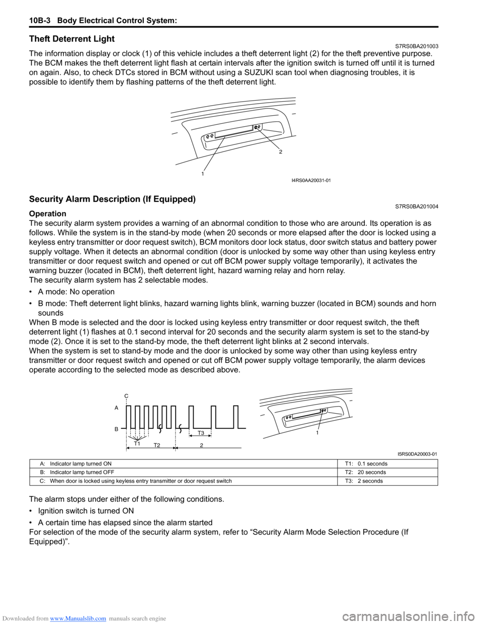
The information display or clock (1) of this vehicle includes a theft deterrent light (2) for the theft preventive purpose.
The BCM makes the theft deterrent light flash at certain interval s after the ignition switch is turned off until it is turned
on again. Also, to check DTCs stored in BCM without usin g a SUZUKI scan tool when diagnosing troubles, it is
possible to identify them by flashing patterns of the theft deterrent light.
Security Alarm Description (If Equipped)S7RS0BA201004
Operation
The security alarm system provides a warning of an abnormal condition to those who are around. Its operation is as
follows. While the system is in the stand- by mode (when 20 seconds or more elapsed after the door is locked using a
keyless entry transmitter or door request switch), BCM monitors door lock status, door switch status and battery power
supply voltage. When it detects an abnormal condition (door is unlocked by some way other than using keyless entry
transmitter or door request switch and opened or cut off BCM power supply voltage temporarily), it activates the
warning buzzer (located in BCM), theft deterr ent light, hazard warning relay and horn relay.
The security alarm system has 2 selectable modes.
• A mode: No operation
• B mode: Theft deterrent light blinks, hazard warning lights blink, warning buzzer (located in BCM) sounds and horn
sounds
When B mode is selected and the door is locked using keyl ess entry transmitter or door request switch, the theft
deterrent light (1) flashes at 0.1 second interval for 20 seconds and the se curity alarm system is set to the stand-by
mode (2). Once it is se t to the stand-by mode, the theft deterrent light blinks at 2 second intervals.
When the system is set to stand-by mode and the door is unlocked by some way other than using keyless entry
transmitter or door request switch and opened or cut off BCM power supply voltage temporarily, the alarm devices
operate according to the selected mode as described above.
The alarm stops under either of the following conditions.
• Ignition switch is turned ON
• A certain time has elapsed since the alarm started
For selection of the mode of the security alarm system , refer to “Security Alarm Mode Selection Procedure (If
Equipped)”.
1 2I4RS0AA20031-01
B A1T3
T1
T2 2
C
I5RS0DA20003-01
A: Indicator lamp turned ON
T1: 0.1 seconds
B: Indicator lamp turned OFF T2: 20 seconds
C: When door is locked using keyless entry tr ansmitter or door request switch T3: 2 seconds
Page 1414 of 1496
Downloaded from www.Manualslib.com manuals search engine 10B-11 Body Electrical Control System:
Customer Complaint Analysis
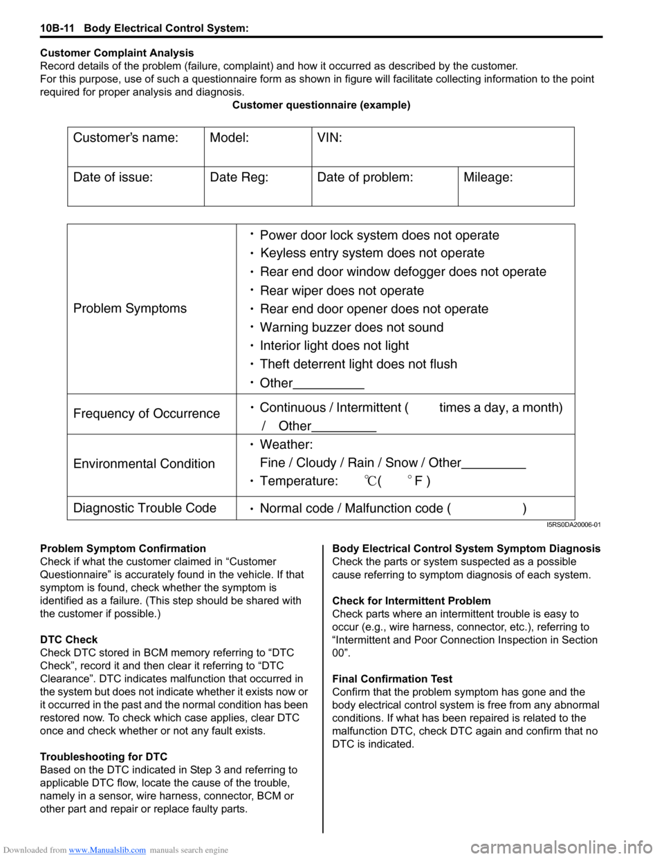
Record details of the problem (failure, complaint) and how it occurred as described by the customer.
For this purpose, use of such a questionnaire form as shown in figure will facilitate collectin g information to the point
required for proper analysis and diagnosis. Customer questionnaire (example)
Problem Symptom Confirmation
Check if what the custom er claimed in “Customer
Questionnaire” is accurately f ound in the vehicle. If that
symptom is found, check whether the symptom is
identified as a failure. (This step should be shared with
the customer if possible.)
DTC Check
Check DTC stored in BCM me mory referring to “DTC
Check”, record it and then clear it referring to “DTC
Clearance”. DTC indicates malfunction that occurred in
the system but does not indicate whether it exists now or
it occurred in the past and the normal condition has been
restored now. To check which case applies, clear DTC
once and check whether or not any fault exists.
Troubleshooting for DTC
Based on the DTC indicated in Step 3 and referring to
applicable DTC flow, locate the cause of the trouble,
namely in a sensor, wire harness, connector, BCM or
other part and repair or replace faulty parts. Body Electrical Control System Symptom Diagnosis
Check the parts or system
suspected as a possible
cause referring to symptom diagnosis of each system.
Check for Intermi ttent Problem
Check parts where an intermit tent trouble is easy to
occur (e.g., wire harness, connector, etc.), referring to
“Intermittent and Poor Connec tion Inspection in Section
00”.
Final Confirmation Test
Confirm that the problem symptom has gone and the
body electrical control system is free from any abnormal
conditions. If what has been repaired is related to the
malfunction DTC, check DTC again and confirm that no
DTC is indicated.
Customers name:
Model:
VIN:
Date of issue:
Date Reg:
Date of problem:
Mileage:
Problem Symptoms
Power door lock system does not operate
Keyless entry system does not operate
Rear end door window defogger does not operate
Rear wiper does not operate
Rear end door opener does not operate
Other
Frequency of Occurrence
Continuous / Intermittent ( times a day, a month)
/ Other
Environmental Condition
Weather:
Fine / Cloudy / Rain / Snow / Other
Temperature: (F )
Diagnostic Trouble Code Normal code / Malfunction code ( )
Warning buzzer does not sound
Interior light does not light
Theft deterrent light does not flush
I5RS0DA20006-01
Page 1418 of 1496
Downloaded from www.Manualslib.com manuals search engine 10B-15 Body Electrical Control System:
Without Using SUZUKI Scan Tool1) Turn ignition switch to OFF position.
2) Perform following Steps a) to d) within 10 seconds af ter ignition switch is turned ON and engine stops.
a) Turn headlight switch to “SMALL” position.
b) Turn headlight switch to “OFF” position.
c) Repeat Steps a) and b) 2 times.
d) Press and release driver side door switch 3 times.
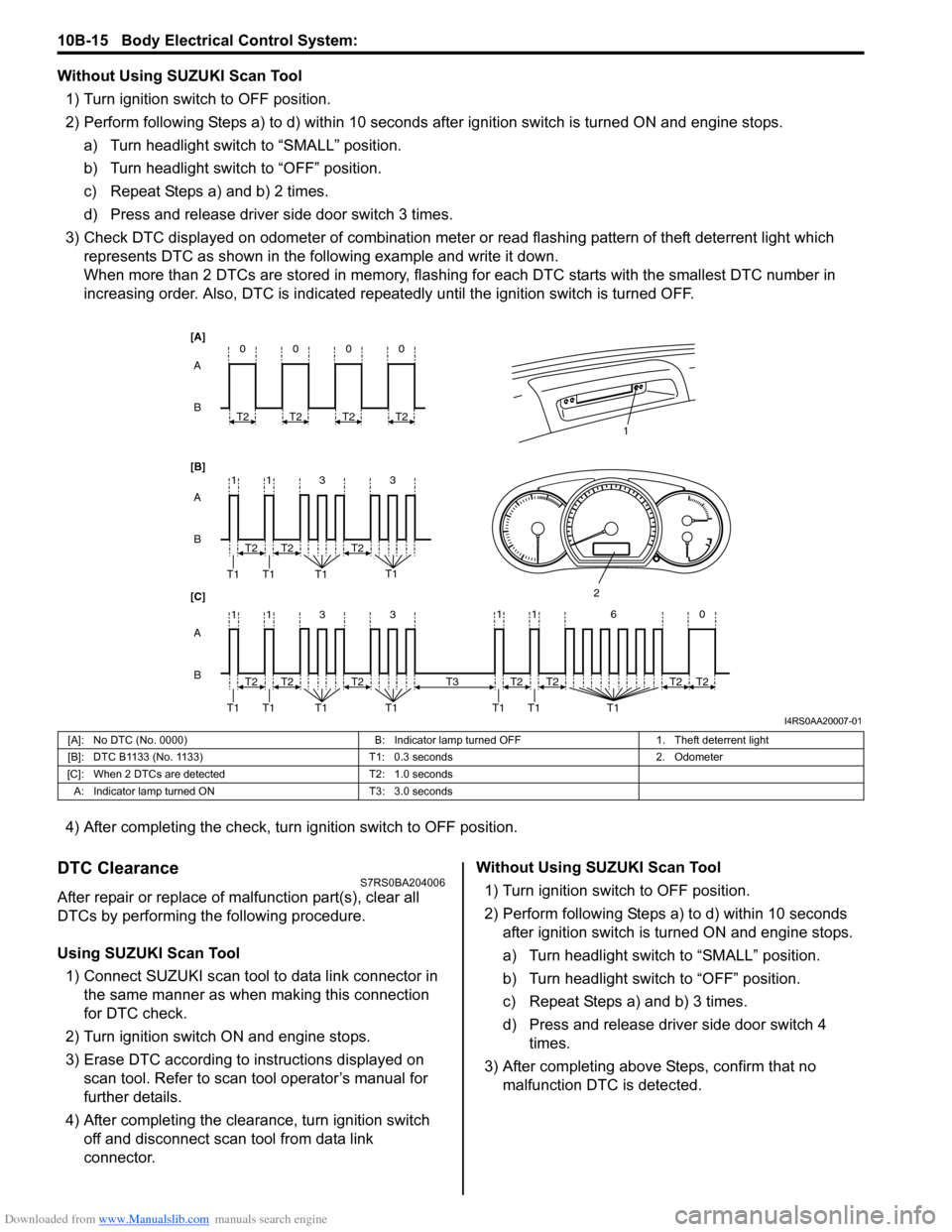
3) Check DTC displayed on odometer of combination meter or read flashing pattern of theft deterrent light which
represents DTC as shown in the following example and write it down.
When more than 2 DTCs are stored in memory, flashing for each DTC starts with the smallest DTC number in
increasing order. Also, DTC is indicated repeatedly until the ignition switch is turned OFF.
4) After completing the check, turn ignition switch to OFF position.
DTC ClearanceS7RS0BA204006
After repair or replace of malfunction part(s), clear all
DTCs by performing the following procedure.
Using SUZUKI Scan Tool 1) Connect SUZUKI scan tool to data link connector in the same manner as when making this connection
for DTC check.
2) Turn ignition switch ON and engine stops.
3) Erase DTC according to instructions displayed on scan tool. Refer to scan tool operator’s manual for
further details.
4) After completing the clear ance, turn ignition switch
off and disconnect scan tool from data link
connector. Without Using SUZUKI Scan Tool
1) Turn ignition switch to OFF position.
2) Perform following Steps a) to d) within 10 seconds after ignition switch is turned ON and engine stops.
a) Turn headlight switch to “SMALL” position.
b) Turn headlight switch to “OFF” position.
c) Repeat Steps a) and b) 3 times.
d) Press and release driver side door switch 4 times.
3) After completing above Steps, confirm that no malfunction DTC is detected.
B A
[B] [A]
[C]
B A B A
3
113
3
113
T2
T1 T1 T1 T1
1
2
T2T2
T2
T1 T1 T1 T1T2T2
0
T2
0
T2
0
T2
0
T2
11 6 0
T1 T1 T1
T2
T3T2T2T2
I4RS0AA20007-01
[A]: No DTC (No. 0000) B: Indicator lamp turned OFF1. Theft deterrent light
[B]: DTC B1133 (No. 1133) T1: 0.3 seconds2. Odometer
[C]: When 2 DTCs are detected T2: 1.0 seconds
A: Indicator lamp tur ned ON T3: 3.0 seconds