2006 SUZUKI SWIFT wheel bolt
[x] Cancel search: wheel boltPage 12 of 1496
Downloaded from www.Manualslib.com manuals search engine 00-7 Precautions:
Warning for Wheel (with tire) RemovalS7RS0B0000003
WARNING!
When removing any of these wheels installed
with wheel bolts, never remove all wheel
bolts at the same time. Leave at least 1 bolt
for each wheel as it is to prevent wheel from
dropping. When removing this remaining 1
bolt, hold wheel and tire so as not to allow
them to come off.
Warning for Handling Emergency Flat Tire
Repair Kit
S7RS0B0000004
WARNING!
If vehicle is equipped with Emergency Flat
Tire Repair Kit instead of spare tire, be sure
to observe “Precaution for Emergency Flat
Tire Repair Kit in Section 2D” when handling
Emergency Flat Tire Repair Kit and repairing
flat tire.
Otherwise, your health may be ruined or it
will be impossible to repair flat tire.
Precautions for Catalytic ConverterS7RS0B0000005
For vehicles equipped with a catalytic converter, use
only unleaded gasoline and be careful not to let a large
amount of unburned gasoline enter the converter or it
can be damaged.
• Conduct a spark jump test only when necessary, make it as short as possible, and do not open the
throttle.
• Conduct engine compression checks within the shortest possible time.
• Avoid situations which can result in engine misfire (e.g. starting the engine when the fuel tank is nearly
empty.)
Precautions for Installing Mobile
Communication Equipment
S7RS0B0000006
When installing mobile communication equipment such
as CB (Citizens-Band)-radi o or cellular-telephone, be
sure to observe the following precautions.
Failure to follow cautions may adversely affect electronic
control system.
• Keep the antenna as far away as possible from the vehicle’s electronic control unit.
• Keep the antenna feeder more than 20 cm (7.9 in.) away from electronic control unit and its wire
harnesses.
• Do not run the antenna feeder parallel with other wire harnesses.
• Confirm that the antenna and feeder are correctly adjusted.
Precaution for CAN Communication SystemS7RS0B0000007
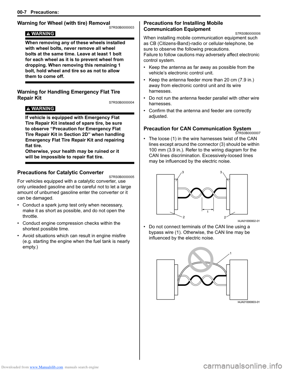
• The loose (1) in the wire harnesses twist of the CAN lines except around the connector (3) should be within
100 mm (3.9 in.). Refer to the wiring diagram for the
CAN lines discrimination. Excessively-loosed lines
may be influenced by the electric noise.
• Do not connect terminals of the CAN line using a bypass wire (1). Otherwise, the CAN line may be
influenced by the electric noise.
33
2
2
1
I4JA01000002-01
1
I4JA01000003-01
Page 37 of 1496
Downloaded from www.Manualslib.com manuals search engine Maintenance and Lubrication: 0B-7
Fuel Filter ReplacementS7RS0B0206011
Fuel filter is installed in fuel pump assembly in fuel tank.
Replace fuel filter or fuel pump assembly with new one,
referring to “Fuel Pump Assembly Removal and
Installation in Section 1G” for proper procedure.
Fuel Tank InspectionS7RS0B0206012
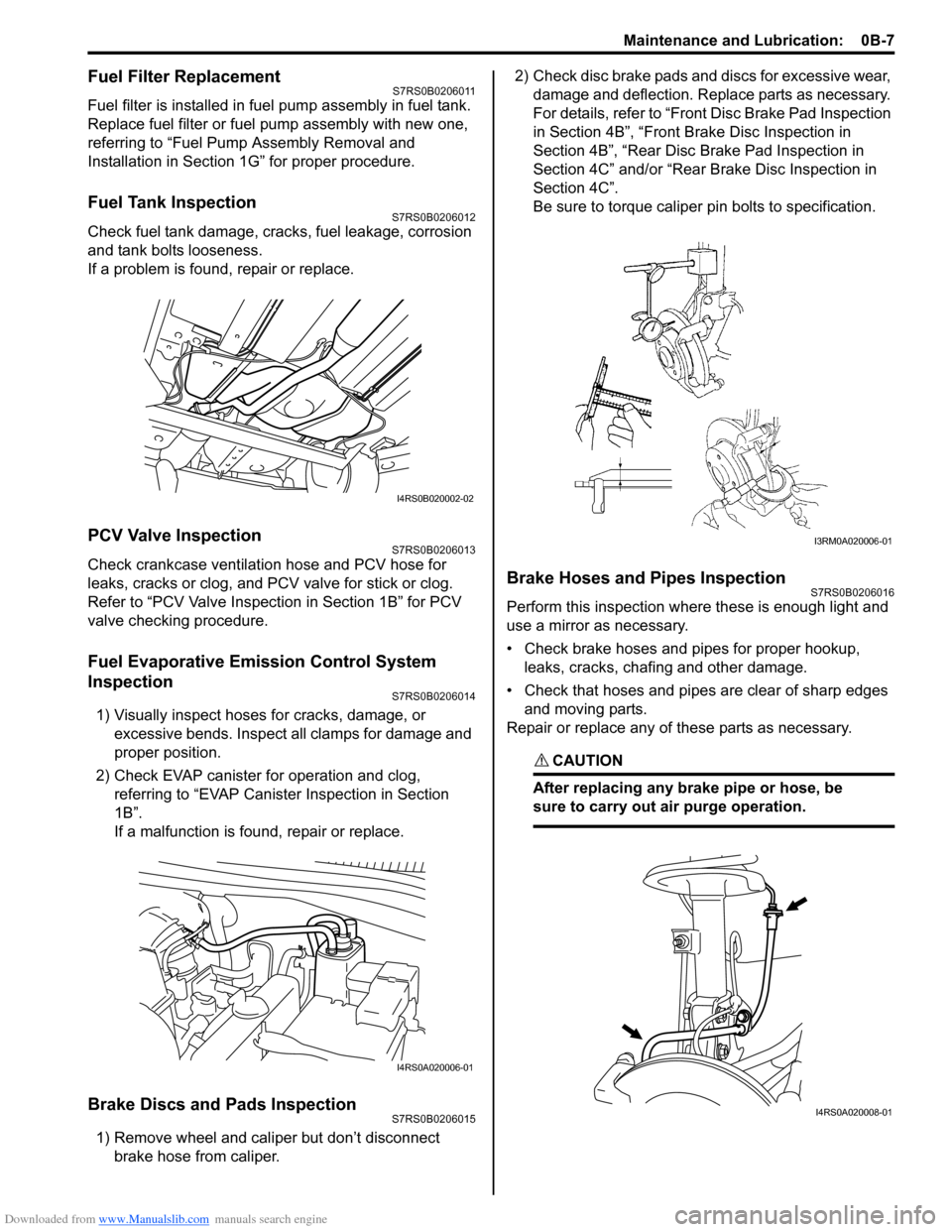
Check fuel tank damage, cracks, fuel leakage, corrosion
and tank bolts looseness.
If a problem is found, repair or replace.
PCV Valve InspectionS7RS0B0206013
Check crankcase ventilation hose and PCV hose for
leaks, cracks or clog, and PCV valve for stick or clog.
Refer to “PCV Valve Inspection in Section 1B” for PCV
valve checking procedure.
Fuel Evaporative Emission Control System
Inspection
S7RS0B0206014
1) Visually inspect hoses for cracks, damage, or excessive bends. Inspect a ll clamps for damage and
proper position.
2) Check EVAP canister for operation and clog, referring to “EVAP Canister Inspection in Section
1B”.
If a malfunction is found, repair or replace.
Brake Discs and Pads InspectionS7RS0B0206015
1) Remove wheel and caliper but don’t disconnect brake hose from caliper. 2) Check disc brake pads and discs for excessive wear,
damage and deflection. Replace parts as necessary.
For details, refer to “Front Disc Brake Pad Inspection
in Section 4B”, “Front Brake Disc Inspection in
Section 4B”, “Rear Disc Brake Pad Inspection in
Section 4C” and/or “Rear Brake Disc Inspection in
Section 4C”.
Be sure to torque caliper pin bolts to specification.
Brake Hoses and Pipes InspectionS7RS0B0206016
Perform this inspection where these is enough light and
use a mirror as necessary.
• Check brake hoses and pipes for proper hookup, leaks, cracks, chafing and other damage.
• Check that hoses and pipes are clear of sharp edges and moving parts.
Repair or replace any of these parts as necessary.
CAUTION!
After replacing any brake pipe or hose, be
sure to carry out air purge operation.
I4RS0B020002-02
I4RS0A020006-01
I3RM0A020006-01
I4RS0A020008-01
Page 39 of 1496
Downloaded from www.Manualslib.com manuals search engine Maintenance and Lubrication: 0B-9
Tires InspectionS7RS0B0206020
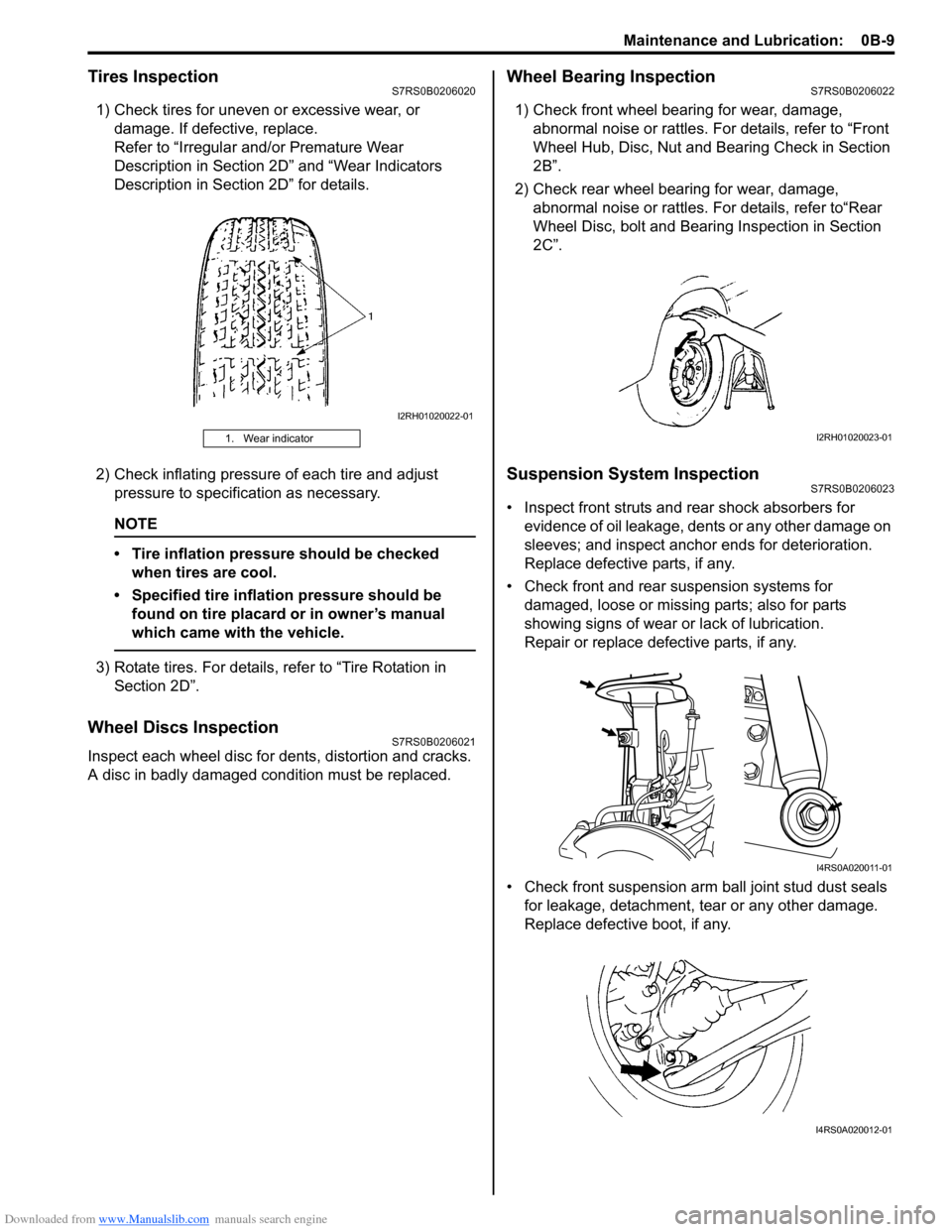
1) Check tires for uneven or excessive wear, or damage. If defective, replace.
Refer to “Irregular and/or Premature Wear
Description in Section 2D” and “Wear Indicators
Description in Section 2D” for details.
2) Check inflating pressure of each tire and adjust pressure to specification as necessary.
NOTE
• Tire inflation pressure should be checked when tires are cool.
• Specified tire inflation pressure should be found on tire placard or in owner’s manual
which came with the vehicle.
3) Rotate tires. For details, refer to “Tire Rotation in Section 2D”.
Wheel Discs InspectionS7RS0B0206021
Inspect each wheel disc for de nts, distortion and cracks.
A disc in badly damaged condition must be replaced.
Wheel Bearing InspectionS7RS0B0206022
1) Check front wheel bearing for wear, damage, abnormal noise or rattles. For details, refer to “Front
Wheel Hub, Disc, Nut and Bearing Check in Section
2B”.
2) Check rear wheel bearing for wear, damage, abnormal noise or rattles. For details, refer to“Rear
Wheel Disc, bolt and Bearing Inspection in Section
2C”.
Suspension System InspectionS7RS0B0206023
• Inspect front struts and rear shock absorbers for evidence of oil leakage, dents or any other damage on
sleeves; and inspect anchor ends for deterioration.
Replace defective parts, if any.
• Check front and rear suspension systems for damaged, loose or missing parts; also for parts
showing signs of wear or lack of lubrication.
Repair or replace defective parts, if any.
• Check front suspension arm ball joint stud dust seals for leakage, detachment, tear or any other damage.
Replace defective boot, if any.
1. Wear indicator
I2RH01020022-01
I2RH01020023-01
I4RS0A020011-01
I4RS0A020012-01
Page 40 of 1496
Downloaded from www.Manualslib.com manuals search engine 0B-10 Maintenance and Lubrication:
Steering System InspectionS7RS0B0206024
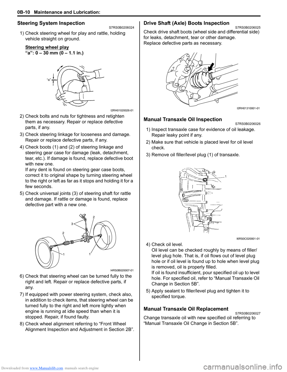
1) Check steering wheel for play and rattle, holding vehicle straight on ground.
Steering wheel play
“a”: 0 – 30 mm (0 – 1.1 in.)
2) Check bolts and nuts for tightness and retighten them as necessary. Repair or replace defective
parts, if any.
3) Check steering linkage for looseness and damage. Repair or replace defective parts, if any.
4) Check boots (1) and (2) of steering linkage and steering gear case for damage (leak, detachment,
tear, etc.). If damage is fo und, replace defective boot
with new one.
If any dent is found on steering gear case boots,
correct it to original shape by turning steering wheel
to the right or left as far as it stops and holding it for a
few seconds.
5) Check universal joints (3) of steering shaft for rattle and damage. If rattle or damage is found, replace
defective part with a new one.
6) Check that steering wheel can be turned fully to the
right and left. Repair or replace defective parts, if
any.
7) If equipped with power steering system, check also, in addition to check items, that steering wheel can be
turned fully to the right and left more lightly when
engine is running at idle speed than when it is
stopped. Repair, if found faulty.
8) Check wheel alignment referring to “Front Wheel Alignment Inspection and Adjustment in Section 2B”.
Drive Shaft (Axle) Boots InspectionS7RS0B0206025
Check drive shaft boots (wheel side and differential side)
for leaks, detachment, tear or other damage.
Replace defective parts as necessary.
Manual Transaxle Oil InspectionS7RS0B0206026
1) Inspect transaxle case for evidence of oil leakage. Repair leaky point if any.
2) Make sure that vehicle is placed level for oil level
check.
3) Remove oil filler/leve l plug (1) of transaxle.
4) Check oil level. Oil level can be checked roughly by means of filler/
level plug hole. That is, if oil flows out of level plug
hole or if oil level is found up to hole when level plug
is removed, oil is properly filled.
If oil is found insufficient, po ur specified oil up to level
hole. For specified oil, refe r to “Manual Transaxle Oil
Change in Section 5B”.
5) Apply sealant to filler/leve l plug and tighten it to
specified torque.
Manual Transaxle Oil ReplacementS7RS0B0206027
Change transaxle oil with new specified oil referring to
“Manual Transaxle Oil Change in Section 5B”.
I2RH01020026-01
2
3
2
1
1
I4RS0B020007-01
I2RH01310001-01
I6RS0C020001-01
Page 304 of 1496
Downloaded from www.Manualslib.com manuals search engine 1D-19 Engine Mechanical:
24) Before removing engine with transaxle from engine compartment, recheck to make sure all hoses,
electric wires and cables are disconnected from
engine and transaxle.
25) Lower engine with transaxle from engine compartment.
CAUTION!
Before lowering engine, to avoid damage to
A/C compressor and clutch operating
cylinder, make clearance by rising them. Be
sure not to damage suspended A/C
compressor and clutch operating cylinder.
26) Disconnect transaxle from engine, referring to “Manual Transaxle Unit Dismounting and
Remounting in Section 5B” or “Automatic Transaxle
Unit Dismounting and Re mounting in Section 5A”.
27) For M/T model, remove clutch cover and clutch disk referring to “Clutch Cover, Clutch Disc and Flywheel
Removal and Installa tion in Section 5C”.
Installation 1) For M/T model, install clutch cover and clutch disk referring to “Clutch Cover, Clutch Disc and Flywheel
Removal and Installa tion in Section 5C”.
2) Connect transaxle to engine referring to “Manual Transaxle Unit Dismounting and Remounting in
Section 5B” or “Automatic Transaxle Unit
Dismounting and Remounting in Section 5A”.
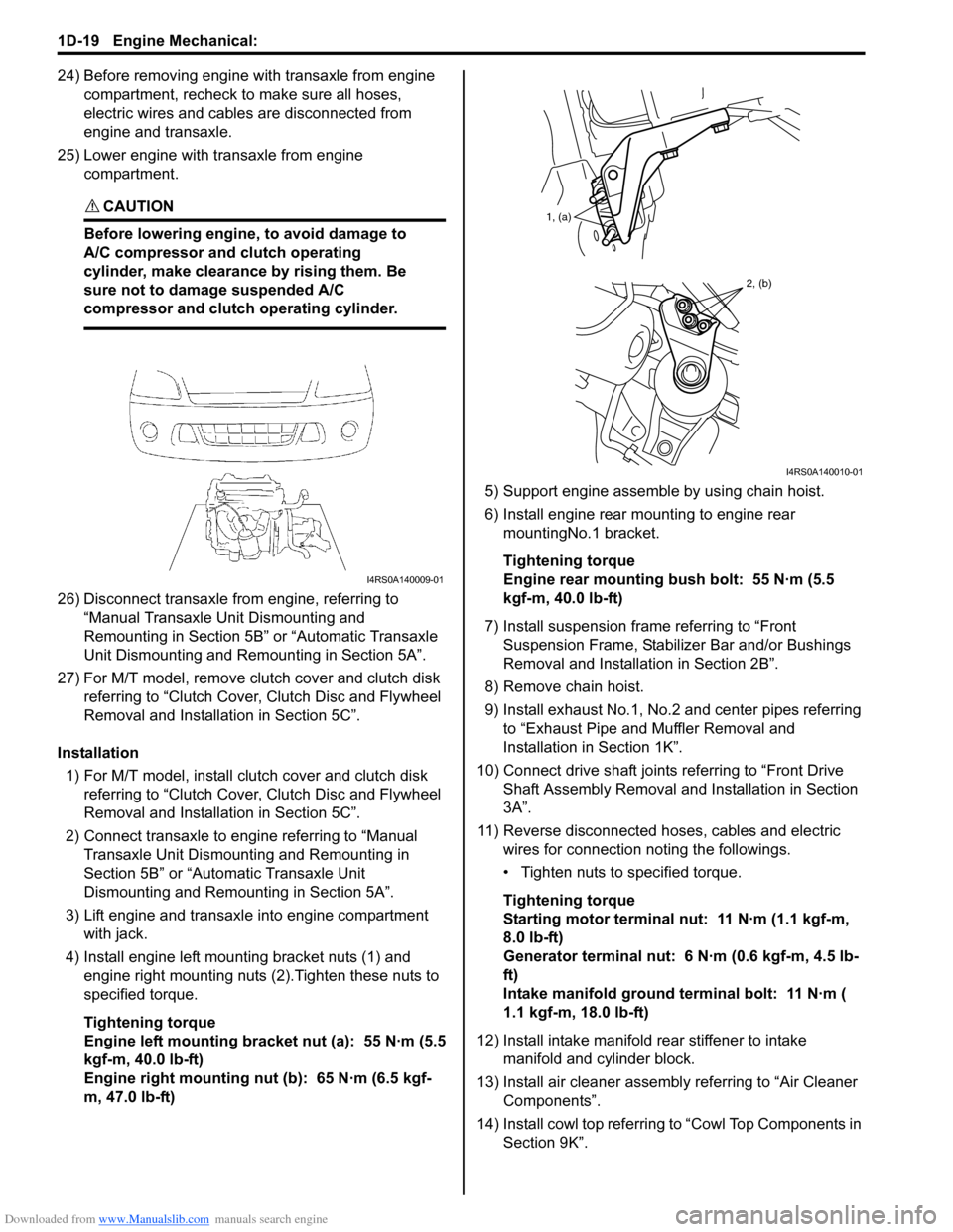
3) Lift engine and transaxle into engine compartment with jack.
4) Install engine left mounting bracket nuts (1) and engine right mounting nuts (2).Tighten these nuts to
specified torque.
Tightening torque
Engine left mounting bracket nut (a): 55 N·m (5.5
kgf-m, 40.0 lb-ft)
Engine right mounting nut (b): 65 N·m (6.5 kgf-
m, 47.0 lb-ft) 5) Support engine assemble by using chain hoist.
6) Install engine rear mounting to engine rear
mountingNo.1 bracket.
Tightening torque
Engine rear mounting bush bolt: 55 N·m (5.5
kgf-m, 40.0 lb-ft)
7) Install suspension frame referring to “Front Suspension Frame, Stabiliz er Bar and/or Bushings
Removal and Installati on in Section 2B”.
8) Remove chain hoist.
9) Install exhaust No.1, No.2 and center pipes referring to “Exhaust Pipe and Muffler Removal and
Installation in Section 1K”.
10) Connect drive shaft joints referring to “Front Drive Shaft Assembly Removal and Installation in Section
3A”.
11) Reverse disconnected hoses, cables and electric wires for connection noting the followings.
• Tighten nuts to specified torque.
Tightening torque
Starting motor terminal nut: 11 N·m (1.1 kgf-m,
8.0 lb-ft)
Generator terminal nut: 6 N·m (0.6 kgf-m, 4.5 lb-
ft)
Intake manifold ground terminal bolt: 11 N·m (
1.1 kgf-m, 18.0 lb-ft)
12) Install intake manifold rear stiffener to intake
manifold and cylinder block.
13) Install air cleaner assembly referring to “Air Cleaner Components”.
14) Install cowl top referring to “Cowl Top Components in
Section 9K”.
I4RS0A140009-01
1, (a)
2, (b)
I4RS0A140010-01
Page 330 of 1496
Downloaded from www.Manualslib.com manuals search engine 1D-45 Engine Mechanical:
Pistons, Piston Rings, Connecting Rods and
Cylinders Removal and Installation
S7RS0B1406030
Removal1) Remove engine assembly from vehicle referring to “Engine Assembly Removal and Installation”.
2) Remove cylinder head referring to “Valves and Cylinder Head Removal and Installation”.
3) Mark cylinder number on all pistons, connecting rods
and connecting rod caps using silver pencil or quick
drying paint.
4) Remove rod bearing caps.
5) Decarbonize top of cylinder bore before removing piston from cylinder.
6) Push piston and connecting rod assembly out through the top of cylinder bore.
Installation 1) Apply engine oil to pistons, rings, cylinder walls, connecting rod bearings and crank pins.
NOTE
Do not apply oil between connecting rod and
bearing or between bearing cap and bearing.
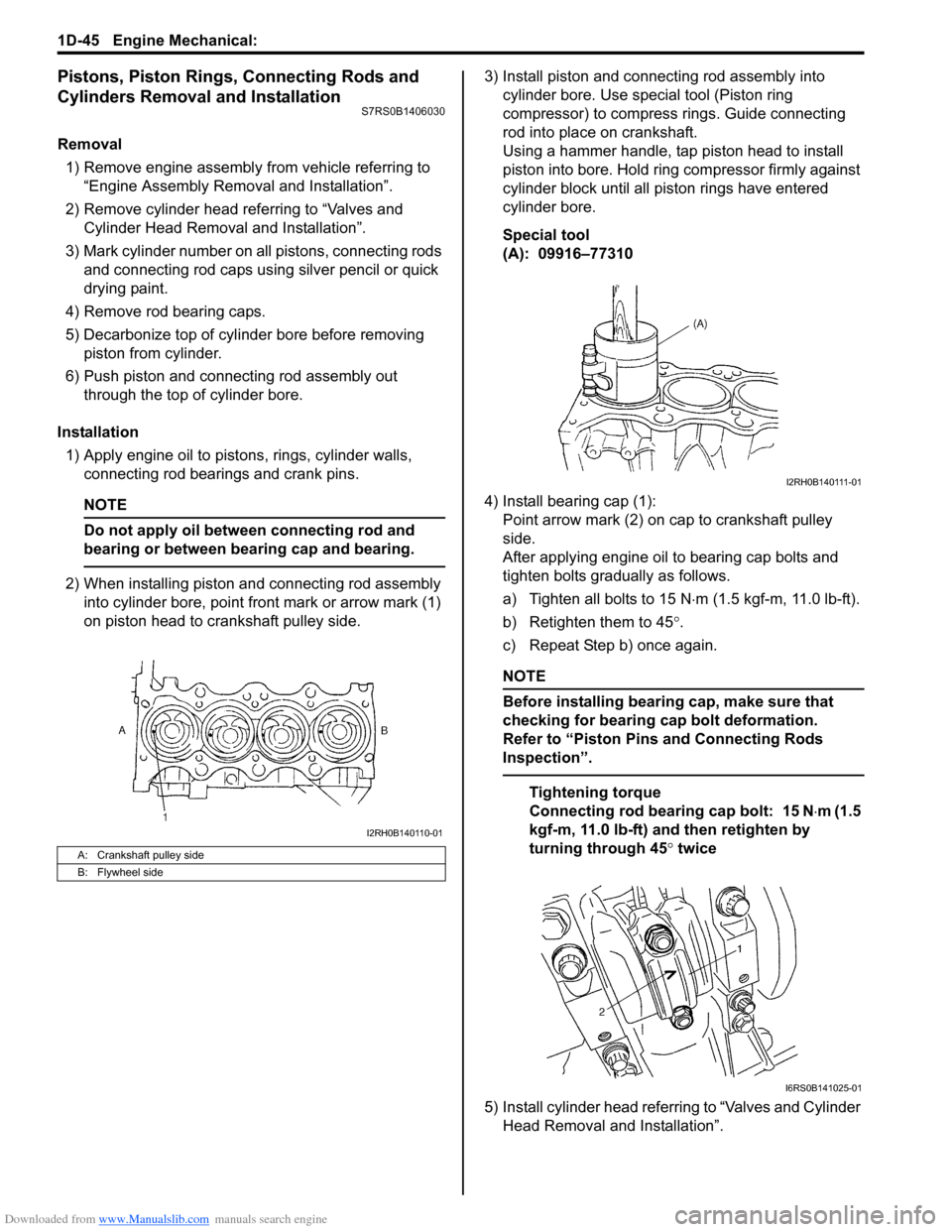
2) When installing piston and connecting rod assembly into cylinder bore, point front mark or arrow mark (1)
on piston head to crankshaft pulley side. 3) Install piston and connecting rod assembly into
cylinder bore. Use special tool (Piston ring
compressor) to compress rings. Guide connecting
rod into place on crankshaft.
Using a hammer handle, tap piston head to install
piston into bore. Hold ring compressor firmly against
cylinder block until all piston rings have entered
cylinder bore.
Special tool
(A): 09916–77310
4) Install bearing cap (1): Point arrow mark (2) on cap to crankshaft pulley
side.
After applying engine oil to bearing cap bolts and
tighten bolts gradually as follows.
a) Tighten all bolts to 15 N ⋅m (1.5 kgf-m, 11.0 lb-ft).
b) Retighten them to 45 °.
c) Repeat Step b) once again.
NOTE
Before installing bearing cap, make sure that
checking for bearing cap bolt deformation.
Refer to “Piston Pins and Connecting Rods
Inspection”.
Tightening torque
Connecting rod bearing cap bolt: 15 N ⋅m (1.5
kgf-m, 11.0 lb-ft) and then retighten by
turning through 45 ° twice
5) Install cylinder head referring to “Valves and Cylinder Head Removal and Installation”.
A: Crankshaft pulley side
B: Flywheel side
I2RH0B140110-01
I2RH0B140111-01
I6RS0B141025-01
Page 338 of 1496
Downloaded from www.Manualslib.com manuals search engine 1D-53 Engine Mechanical:
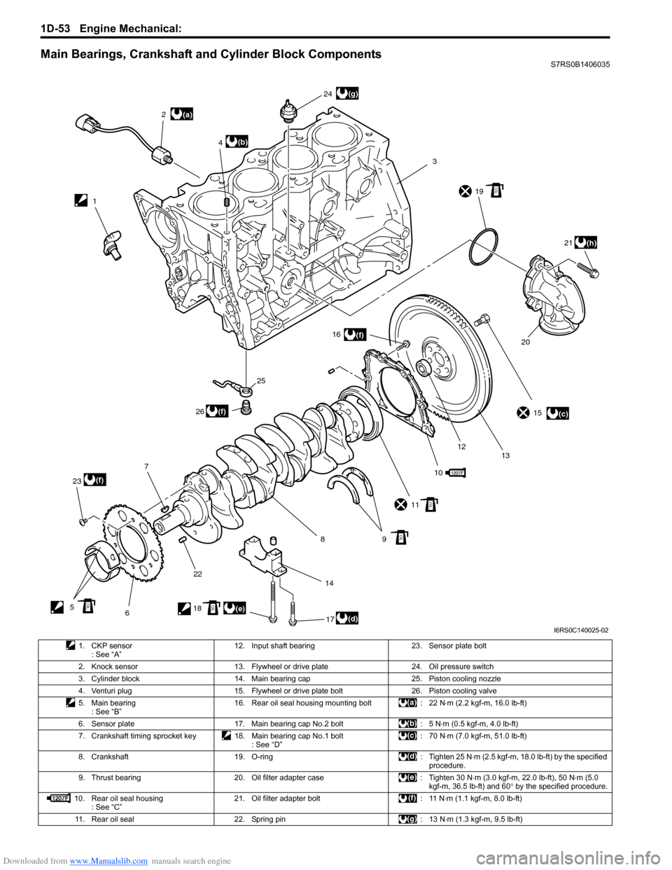
Main Bearings, Crankshaft and Cylinder Block ComponentsS7RS0B1406035
(a)
(c)
(d)(e)
(b)
(f)
(f)
(f)
(g)
(h)
12
3
4
5 67
8910
11 15
12 13
14 16
17
18 19
2021
22
23 24
25
26
OIL
OIL
OIL
OILOIL
I6RS0C140025-02
1. CKP sensor : See “A” 12. Input shaft bearing 23. Sensor plate bolt
2. Knock sensor 13. Flywheel or drive plate 24. Oil pressure switch 3. Cylinder block 14. Main bearing cap 25. Piston cooling nozzle
4. Venturi plug 15. Flywheel or drive plate bolt 26. Piston cooling valve
5. Main bearing : See “B” 16. Rear oil seal housing mounting bolt : 22 N
⋅m (2.2 kgf-m, 16.0 lb-ft)
6. Sensor plate 17. Main bearing cap No.2 bolt : 5 N ⋅m (0.5 kgf-m, 4.0 lb-ft)
7. Crankshaft timing sprocket key 18. Main bearing cap No.1 bolt : See “D”:70 N
⋅m (7.0 kgf-m, 51.0 lb-ft)
8. Crankshaft 19. O-ring : Tighten 25 N ⋅m (2.5 kgf-m, 18.0 lb-ft) by the specified
procedure.
9. Thrust bearing 20. Oil filter adapter case : Tighten 30 N ⋅m (3.0 kgf-m, 22.0 lb-ft), 50 N⋅m (5.0
kgf-m, 36.5 lb-ft) and 60 ° by the specified procedure.
10. Rear oil seal housing : See “C” 21. Oil filter adapter bolt : 11 N
⋅m (1.1 kgf-m, 8.0 lb-ft)
11. Rear oil seal 22. Spring pin : 13 N ⋅m (1.3 kgf-m, 9.5 lb-ft)
Page 339 of 1496
Downloaded from www.Manualslib.com manuals search engine Engine Mechanical: 1D-54
Main Bearings, Crankshaft and Cylinder Block
Removal and Installation
S7RS0B1406036
Removal1) Remove engine assembly from vehicle referring to “Engine Assembly Removal and Installation”.
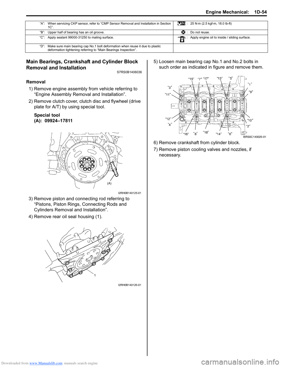
2) Remove clutch cover, clut ch disc and flywheel (drive
plate for A/T) by using special tool.
Special tool
(A): 09924–17811
3) Remove piston and connecting rod referring to “Pistons, Piston Rings, Connecting Rods and
Cylinders Removal and Installation”.
4) Remove rear oil seal housing (1). 5) Loosen main bearing cap No.1 and No.2 bolts in
such order as indicated in figure and remove them.
6) Remove crankshaft from cylinder block.
7) Remove piston cooling valves and nozzles, if necessary.
“A”: When servicing CKP sensor, refer to “CMP Sensor Removal and Installation in Section 1C”. :25 N
⋅m (2.5 kgf-m, 18.0 lb-ft)
“B”: Upper half of bearing has an oil groove. : Do not reuse.
“C”: Apply sealant 99000-31250 to mating surface. : Apply engine oil to inside / sliding surface.
“D”: Make sure main bearing cap No.1 bolt deformation when reuse it due to plastic deformation tightening referring to “Main Bearings Inspection”.
I2RH0B140125-01
I2RH0B140126-01
I6RS0C140026-01