2006 SUZUKI SWIFT tel
[x] Cancel search: telPage 276 of 1496
Downloaded from www.Manualslib.com manuals search engine 1C-4 Engine Electrical Devices:
TP Sensor Performance Check1) Remove air cleaner outlet hose.
2) Turn OFF ignition switch.
3) Disconnect connector from electric throttle body assembly.
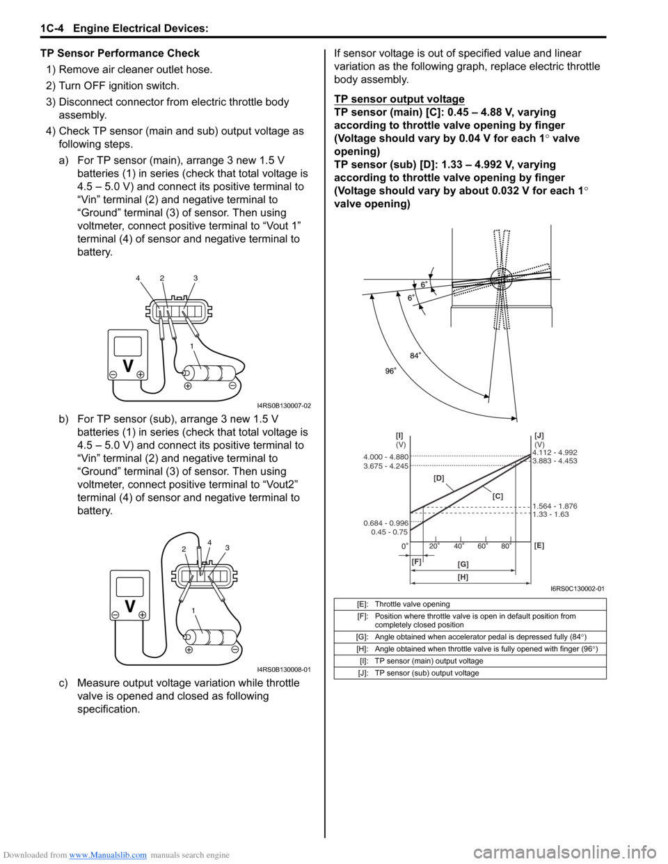
4) Check TP sensor (main and sub) output voltage as following steps.
a) For TP sensor (main), arrange 3 new 1.5 V batteries (1) in series (c heck that total voltage is
4.5 – 5.0 V) and connect its positive terminal to
“Vin” terminal (2) and negative terminal to
“Ground” terminal (3) of sensor. Then using
voltmeter, connect positive terminal to “Vout 1”
terminal (4) of sensor and negative terminal to
battery.
b) For TP sensor (sub), arrange 3 new 1.5 V batteries (1) in series (c heck that total voltage is
4.5 – 5.0 V) and connect its positive terminal to
“Vin” terminal (2) and negative terminal to
“Ground” terminal (3) of sensor. Then using
voltmeter, connect positive terminal to “Vout2”
terminal (4) of sensor and negative terminal to
battery.
c) Measure output voltage variation while throttle valve is opened and closed as following
specification. If sensor voltage is out of specified value and linear
variation as the following gra
ph, replace electric throttle
body assembly.
TP sensor output voltage
TP sensor (main) [C]: 0.45 – 4.88 V, varying
according to throttle valve opening by finger
(Voltage should vary by 0.04 V for each 1° valve
opening)
TP sensor (sub) [D]: 1.33 – 4.992 V, varying
according to throttle valve opening by finger
(Voltage should vary by about 0.032 V for each 1 °
valve opening)
1
42 3
I4RS0B130007-02
1
3
2 4
I4RS0B130008-01
[E]: Throttle valve opening
[F]: Position where throttle valve is open in default position from completely closed position
[G]: Angle obtained when accelerator pedal is depressed fully (84 °)
[H]: Angle obtained when throttle valve is fully opened with finger (96 °)
[I]: TP sensor (main) output voltage
[J]: TP sensor (sub) output voltage
[D]
[C][J]
(V)
[I]
(V)
[F] [G] [E]
0.45 - 0.75
0.684 - 0.996 3.675 - 4.245 4.000 - 4.880
1.33 - 1.63 1.564 - 1.876 3.883 - 4.453 4.112 - 4.992
[H]
I6RS0C130002-01
Page 280 of 1496
Downloaded from www.Manualslib.com manuals search engine 1C-8 Engine Electrical Devices:
Installation
Reverse removal procedure noting the following.
• Tighten heated oxygen sensor to specified torque.Tightening torque
Heated oxygen sensor (a): 45 N·m (4.5 kgf-m,
32.5 lb-ft)
• Install exhaust manifold referring to “Exhaust Manifold Removal and Installation in Section 1K”, if removed.
• Connect connector of heated oxygen sensor and clamp wire harness securely.
• After installing heated oxygen sensor, start engine and check that no exhaust gas leakage exists.
CMP Sensor Removal and InstallationS7RS0B1306012
Removal
1) Disconnect negative (–) cable at battery.
2) Disconnect connector from CMP sensor.
3) Remove CMP sensor from cylinder head.
Installation 1) Install CMP sensor to cylinder head.
Tightening torque
CMP sensor bolt (a): 10 N·m (1.0 kgf-m, 7.5 lb-ft)
2) Connect connector to CMP sensor securely.
3) Connect negative (–) cable to battery.
Camshaft Position (CMP) Sensor InspectionS7RS0B1306013
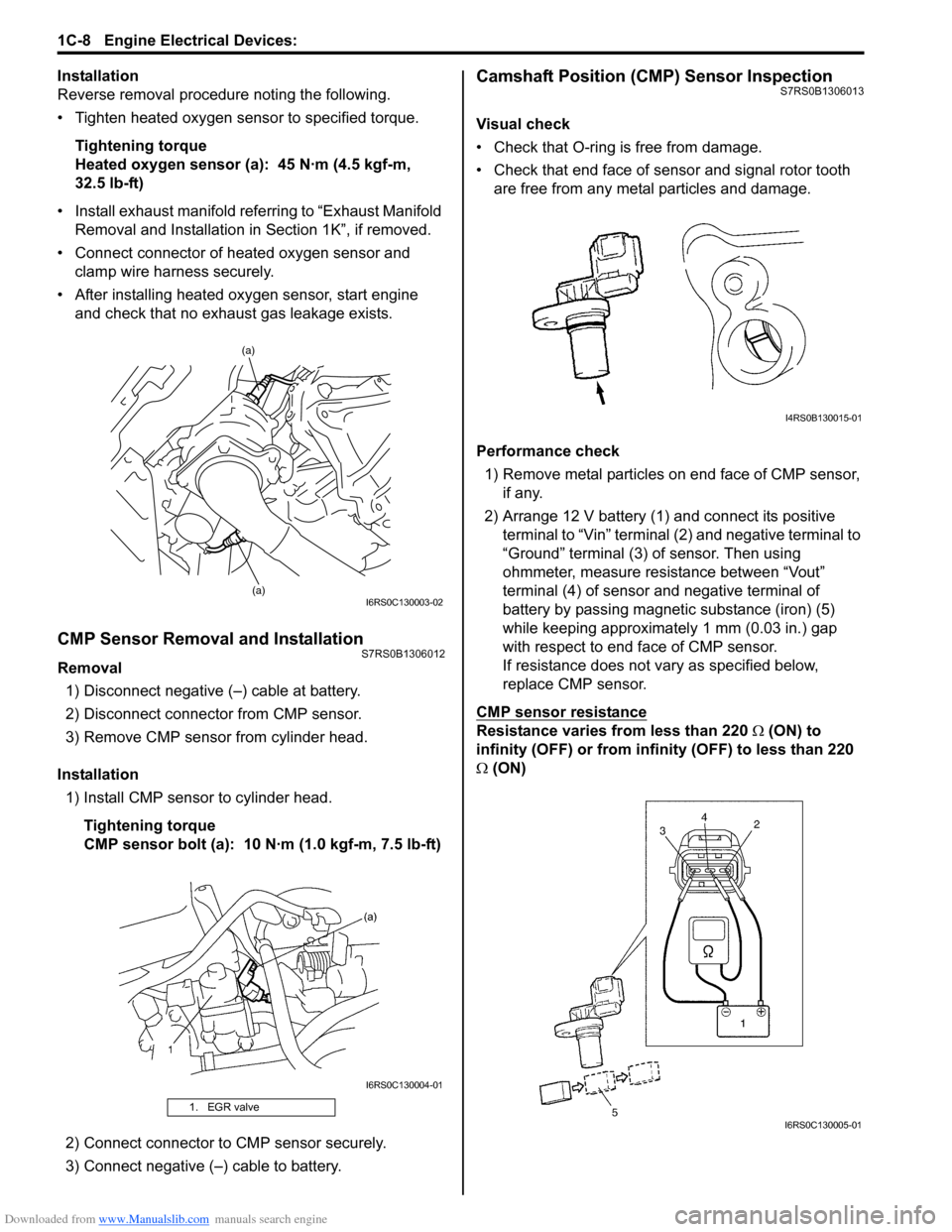
Visual check
• Check that O-ring is free from damage.
• Check that end face of sensor and signal rotor tooth are free from any metal particles and damage.
Performance check 1) Remove metal particles on end face of CMP sensor, if any.
2) Arrange 12 V battery (1) and connect its positive terminal to “Vin” terminal (2) and negative terminal to
“Ground” terminal (3) of sensor. Then using
ohmmeter, measure resistance between “Vout”
terminal (4) of sensor and negative terminal of
battery by passing magnetic substance (iron) (5)
while keeping approximately 1 mm (0.03 in.) gap
with respect to end face of CMP sensor.
If resistance does not vary as specified below,
replace CMP sensor.
CMP sensor resistance
Resistance varies from less than 220 Ω (ON) to
infinity (OFF) or from infinity (OFF) to less than 220
Ω (ON)
1. EGR valve
(a)
(a)
I6RS0C130003-02
I6RS0C130004-01
I4RS0B130015-01
I6RS0C130005-01
Page 281 of 1496
Downloaded from www.Manualslib.com manuals search engine Engine Electrical Devices: 1C-9
CKP Sensor Removal and InstallationS7RS0B1306014
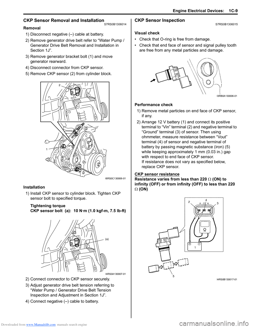
Removal1) Disconnect negative (–) cable at battery.
2) Remove generator drive belt refer to “Water Pump / Generator Drive Belt Remo val and Installation in
Section 1J”.
3) Remove generator bracket bolt (1) and move generator rearward.
4) Disconnect connector from CKP sensor.
5) Remove CKP sensor (2) from cylinder block.
Installation 1) Install CKP sensor to cylinder block. Tighten CKP sensor bolt to specified torque.
Tightening torque
CKP sensor bolt (a): 10 N·m (1.0 kgf-m, 7.5 lb-ft)
2) Connect connector to CKP sensor securely.
3) Adjust generator drive belt tension referring to “Water Pump / Generator Drive Belt Tension
Inspection and Adjustment in Section 1J”.
4) Connect negative (–) cable to battery.
CKP Sensor InspectionS7RS0B1306015
Visual check
• Check that O-ring is free from damage.
• Check that end face of sensor and signal pulley tooth are free from any metal particles and damage.
Performance check 1) Remove metal particles on end face of CKP sensor, if any.
2) Arrange 12 V battery (1) and connect its positive terminal to “Vin” terminal (2) and negative terminal to
“Ground” terminal (3) of sensor. Then using
ohmmeter, measure resistance between “Vout”
terminal (4) of sensor and negative terminal of
battery by passing magnetic substance (iron) (5)
while keeping approximately 1 mm (0.03 in.) gap
with respect to end face of CKP sensor.
If resistance does not vary as specified below,
replace CKP sensor.
CKP sensor resistance
Resistance varies from less than 220 Ω (ON) to
infinity (OFF) or from infinity (OFF) to less than 220
Ω (ON)
2
1
I6RS0C130006-01
(a)
I4RS0A130007-01
I3RB0A130006-01
I4RS0B130017-01
Page 287 of 1496
Downloaded from www.Manualslib.com manuals search engine Engine Mechanical: 1D-2
Camshaft Position Control (VVT Variable Valve Timing) System DescriptionS7RS0B1401002
System Description
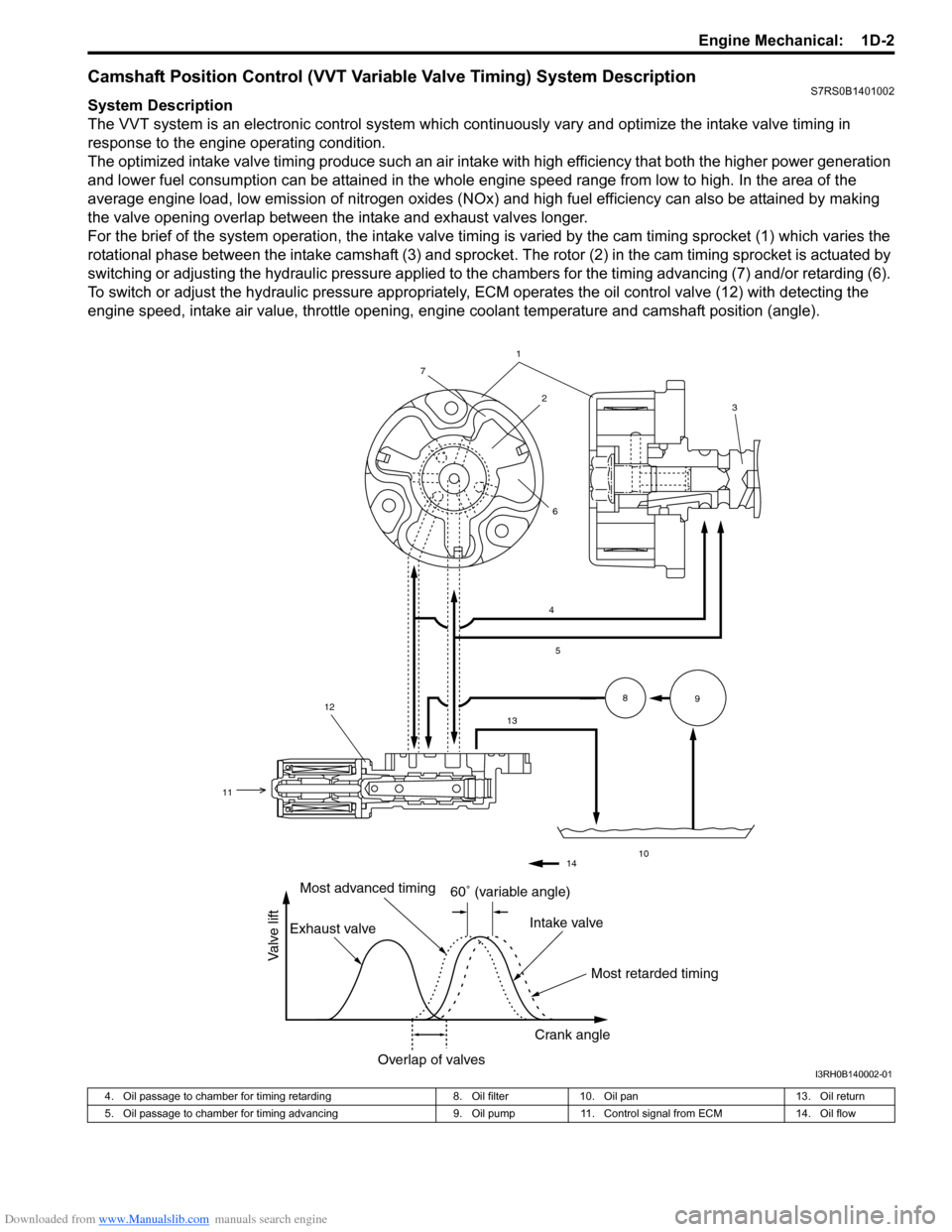
The VVT system is an electronic control system which continuously vary and optimize the intake valve timing in
response to the engine operating condition.
The optimized intake valve timing produce such an air intake with high efficiency that both the higher power generation
and lower fuel consumption can be attained in the whole engine speed range from low to high. In the area of the
average engine load, low emission of nitrogen oxides (NOx) and high fuel efficiency can also be attained by making
the valve opening overlap between the intake and exhaust valves longer.
For the brief of the system operation, the intake valve timing is varied by the cam timing sprocket (1) which varies the
rotational phase between the intake camshaft (3) and sprocket . The rotor (2) in the cam timing sprocket is actuated by
switching or adjusting the hydraulic pressure applied to the chambers for the timing advancing (7) and/or retarding (6).
To switch or adjust the hydraulic pressure appropriately, ECM operates the oil control valve (12) with detecting the
engine speed, intake air value, throttle opening, engine coolant temperature and camshaft position (angle).
1
4
5
13
10
89
2
7
6
12
11
3
14
60� (variable angle)
Most retarded timing
Most advanced timing
Exhaust valve Intake valve
Crank angle
Overlap of valves
Valve lift
I3RH0B140002-01
4. Oil passage to chamber for timing retarding 8. Oil filter10. Oil pan 13. Oil return
5. Oil passage to chamber for timing advancing 9. Oil pump11. Control signal from ECM 14. Oil flow
Page 292 of 1496

Downloaded from www.Manualslib.com manuals search engine 1D-7 Engine Mechanical:
Replacement of Shim1) Close the valve whose shim (2) is to be replaced by turning crankshaft, then tu rn tappet (3) till its cut
section (1) faces inside as shown in the figure.
2) Lift down the valve by turning crankshaft to 360° .
3) Hold tappet at that position using special tool as follows.
a) Remove its housing bolts.
b) Check housing No. and select special tool corresponding to housing No., referring to
“Special tool selection table”.
Special tool selection table
c) Hold down the tappet so as not to contact the shim by installing special tool on camshaft
housing with housing bolt (1) tighten housing
bolts by hand.
Special tool
(A): 09916–67020
(A): 09916–67021 4) Turn camshaft by approximately 90
° clockwise and
remove shim (3).
WARNING!
Never put in the hand between camshaft and
tappet.
5) Using a micrometer (2), measure the thickness of the removed shim (1), and determine replacement
shim by calculating the thickness of new shim with
the following formula and table.
Shim thickness specification
Intake side:
A = B + C – 0.20 mm (0.008 in.)
Exhaust side:
A = B + C – 0.30 mm (0.012 in.)
A: Thickness of new shim
B: Thickness of removed shim
C: Measured valve clearance
No. on camshaft
housing Embossed mark on
special tool
I2 IN2
I3, I4, I5 IN345
E2 EX2
E3, E4, E5 EX345
A: I: Intake side or E: Exhaust side
B: Position from timing chain side
C: Pointing to timing chain side
I2RH0B140006-01
I2RH0B140011-01
1. Special tool
2. Magnet
I6RS0B141028-01
I2RH0B140013-01
I2RH0B140014-01
Page 389 of 1496

Downloaded from www.Manualslib.com manuals search engine Fuel System: 1G-14
Fuel Tank Purging ProcedureS7RS0B1706015
WARNING!
• Before starting the following procedure, be sure to observe “Precautions on Fuel
System Service” in order to reduce the risk
or fire and personal injury.
• This purging procedure will not remove all fuel vapor.
Do not attempt any repair on tank using
heat of flame as an explosion resulting in
personal injury could occur.
CAUTION!
Never remain water in fu el tank after washing,
or fuel tank inside will get corrosion.
The following procedure are used for purging fuel tank.
1) After removing fuel tank, remove all hoses, pipes and fuel pump assembly from fuel tank.
2) Drain all remaining fuel from tank.
3) Place fuel tank to flushing area.
4) Fill tank with warm water or tap water, and agitate
vigorously and drain. Repeat this washing until
inside of tank is clean. Replace tank if its inside is
rusty.
5) Completely flush out rema ining water after washing.
Fuel Pump On-Vehicle InspectionS7RS0B1706016
WARNING!
Before starting the following procedure, be
sure to observe “Precautions on Fuel System
Service” in order to reduce the risk or fire
and personal injury.
NOTE
The fuel pressure regulator is incorporated
with the fuel pump assembly so individual
inspection of it is impossible.
1) Remove filler cap and turn ON ignition switch (2).
Then fuel pump operating sound should be heard
from fuel filler (1) for about 2 seconds and stop. Be
sure to reinstall fuel filler cap after checking.
If the check result is not satisfactory, go to “Fuel
Pump and Its Circuit Check in Section 1A”. 2) Turn OFF ignition switch and leave over 10 minutes
as it is.
3) Fuel pressure should be felt at fuel feed hose (1) for about 2 seconds after ignition switch ON.
If fuel pressure is not felt, go to “Fuel Pressure
Check in Section 1A”.
Fuel Pump Assembly Removal and InstallationS7RS0B1706017
WARNING!
Before starting the following procedure, be
sure to observe “Precautions on Fuel System
Service” in order to reduce the risk or fire
and personal injury.
Removal
1) Remove fuel tank from vehicle. Refer to “Fuel Tank Removal and Installation”.
2) Disconnect fuel feed pipe (1) from fuel pump assembly (2) referring to “Fuel Hose Disconnecting
and Reconnecting”.
IVSY01170013-01
1I3RM0A170019-01
1
2
I6RS0C170008-02
Page 414 of 1496

Downloaded from www.Manualslib.com manuals search engine 1J-4 Charging System:
Diagnostic Information and Procedures
Battery InspectionS7RS0B1A04001
Common Causes of Failure
A battery is not designed to last indefinitely; however, with proper care, it will provide many years of service. If the
battery performs satisfactorily during te st but fails to operate properly for no apparent reason, the following are some
factors that may point to the cause of trouble:
• Accessories left on overnight or for an extended period without the generator operating.
• Slow average driving speeds for short periods.
• Electrical load exceeding generator output partic ularly with addition of aftermarket equipment.
• Defects in charging system such as high resistance, s lipping drive belt, loose generator output terminal, faulty
generator or voltage regulator, Refer to “Generator Symptom Diagnosis”.
• Battery abuse, including failure to keep battery cable terminals clean and tight or loose battery hold down.
• Mechanical problems in electrical sys tem such as shorted or pinched wires.
Visual Inspection
Check for obvious damage, such as cracked or broken case or cover, that could permit loss of electrolyte. If obvious
damage is noted, replace battery. Determine cause of damage and correct as needed.
Generator Symptom DiagnosisS7RS0B1A04002
CAUTION!
• Do not mistake polarities of “IG” terminal and “L” terminal.
• Do not create short circuit between “IG” and “L” terminals. Always connect these terminals through a lamp.
• Do not connect any load between “L” and “E” terminals.
• When connecting charger or booster battery to vehicle battery, refer to “Jump Starting in Case of Emergency”.
Trouble in charging system will show up as one or more of the following conditions:
1) Faulty indicator lamp operation.
2) An undercharged battery as evidenced by slow cranking or indicator dark.
3) An overcharged battery as evidenced by ex cessive spewing of electrolyte from vents.
Condition Possible cause Correction / Reference Item
Noisy generator Loose drive belt Adjust or replace drive belt.
Loose drive belt pulley Tighten by specified torque.
Loose mounting bolts Tighten by specified torque.
Worn or dirty bearings Replace.
Defective diode or stator Replace.
Charge light does not
light with ignition ON and
engine off Fuse blown
Replace fuse and check for shorted circuit.
Indicator lamp (LED) faulty Replace combination meter.
Wiring connection loose Tighten loose connection.
IC regulator or field coil faulty Replace.
Poor contact between brush and slip
ring Repair or replace.
Charge light does not go
out with engine running
(battery requires frequent
recharging) Drive belt loose or worn
Adjust or replace drive belt.
IC regulator or generator faulty Replace.
Wiring faulty Repair wiring.
Page 416 of 1496
Downloaded from www.Manualslib.com manuals search engine 1J-6 Charging System:
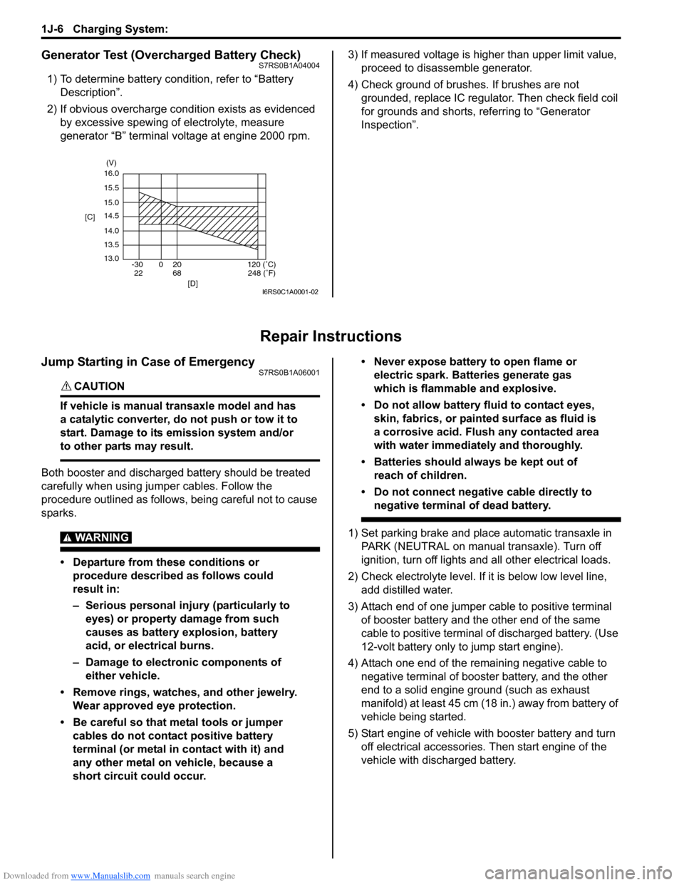
Generator Test (Overcharged Battery Check)S7RS0B1A04004
1) To determine battery condition, refer to “Battery Description”.
2) If obvious overcharge condition exists as evidenced by excessive spewing of electrolyte, measure
generator “B” terminal voltage at engine 2000 rpm. 3) If measured voltage is higher than upper limit value,
proceed to disassemble generator.
4) Check ground of brushes. If brushes are not grounded, replace IC regulator. Then check field coil
for grounds and shorts, referring to “Generator
Inspection”.
Repair Instructions
Jump Starting in Case of EmergencyS7RS0B1A06001
CAUTION!
If vehicle is manual transaxle model and has
a catalytic converter, do not push or tow it to
start. Damage to its emission system and/or
to other parts may result.
Both booster and discharged battery should be treated
carefully when using ju mper cables. Follow the
procedure outlined as follows, being careful not to cause
sparks.
WARNING!
• Departure from these conditions or procedure described as follows could
result in:
– Serious personal injury (particularly to eyes) or property damage from such
causes as battery explosion, battery
acid, or electrical burns.
– Damage to electronic components of either vehicle.
• Remove rings, watches, and other jewelry. Wear approved eye protection.
• Be careful so that metal tools or jumper cables do not contact positive battery
terminal (or metal in contact with it) and
any other metal on vehicle, because a
short circuit could occur. • Never expose battery to open flame or
electric spark. Batteries generate gas
which is flammable and explosive.
• Do not allow battery fluid to contact eyes, skin, fabrics, or painted surface as fluid is
a corrosive acid. Flush any contacted area
with water immediately and thoroughly.
• Batteries should always be kept out of reach of children.
• Do not connect negative cable directly to negative terminal of dead battery.
1) Set parking brake and place automatic transaxle in PARK (NEUTRAL on manual transaxle). Turn off
ignition, turn off lights and all other electrical loads.
2) Check electrolyte level. If it is below low level line, add distilled water.
3) Attach end of one jumper cable to positive terminal of booster battery and the other end of the same
cable to positive terminal of discharged battery. (Use
12-volt battery only to jump start engine).
4) Attach one end of the remaining negative cable to negative terminal of booster battery, and the other
end to a solid engine ground (such as exhaust
manifold) at least 45 cm (18 in.) away from battery of
vehicle being started.
5) Start engine of vehicle with booster battery and turn off electrical accessories. Then start engine of the
vehicle with discharged battery.
16.0
15.5
15.0
14.5
14.0
13.5
13.0 -30 0 20
[C]
[D]
68
22120 (˚C)
248 (˚F)
(V)
I6RS0C1A0001-02