2006 SUZUKI SWIFT E23-29
[x] Cancel search: E23-29Page 191 of 1496
Downloaded from www.Manualslib.com manuals search engine Engine General Information and Diagnosis: 1A-141
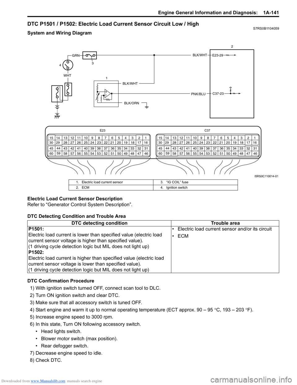
DTC P1501 / P1502: Electric Load Current Sensor Circuit Low / HighS7RS0B1104059
System and Wiring Diagram
Electric Load Current Sensor Description
Refer to “Generator Control System Description”.
DTC Detecting Condition and Trouble Area
DTC Confirmation Procedure1) With ignition switch turned OFF, connect scan tool to DLC.
2) Turn ON ignition switch and clear DTC.
3) Make sure that all accessory switch is tuned OFF.
4) Start engine and warm it up to normal operating temperature (ECT approx. 90 – 95 °C, 193 – 203 °F).
5) Increase engine speed to 3000 rpm.
6) In this state, Turn ON following accessory switch.
• Head lights switch.
• Blower motor switch (max position).
• Rear defogger switch.
7) Decrease engine speed to idle.
8) Check DTC.
E23 C37
34
1819
567
1011
17
20
47 46
495051
2122
52 16
25 9
24
14
29
55
57 54 53
59
60 58 2
262728
15
30
56 4832 31
34353637
40
42 39 38
44
45 43 41 331
1213
238
34
1819
567
1011
17
20
47 46
495051
2122
52 16
25 9
24
14
29
55
57 54 53
59
60 58 2
262728
15
30
56 4832 31
34353637
40
42 39 38
44
45 43 41 331
1213
238
BLK/WHT
WHT
GRN
4
3 2
E23-29
1
C37-23PNK/BLU
BLK/ORN
BLK/WHT
I5RS0C110014-01
1. Electric load current sensor
3. “IG COIL” fuse
2. ECM 4. Ignition switch
DTC detecting condition Trouble area
P1501:
Electric load current is lower th an specified value (electric load
current sensor voltage is higher than specified value).
(1 driving cycle detection logic but MIL does not light up)
P1502:
Electric load current is higher than specified value (electric load
current sensor voltage is lo wer than specified value).
(1 driving cycle detection logic but MIL does not light up) • Electric load current sensor and/or its circuit
•ECM
Page 202 of 1496

Downloaded from www.Manualslib.com manuals search engine 1A-152 Engine General Information and Diagnosis:
DTC P2101: Throttle Actuator Control Motor Circuit Range / PerformanceS7RS0B1104067
Wiring Diagram
DTC Detecting Condition and Trouble Area
DTC Confirmation Procedure1) With ignition switch turned OFF, connect scan tool.
2) Turn ON ignition switch and clear DTC using scan tool.
3) Keep the accelerator pedal at idle position for 2 seconds.
4) Keep the accelerator pedal at fully depressed position for 2 seconds.
5) Repeat Step 3) and 4) for 3 times.
6) Check DTC.
E23 C37
34
1819
567
1011
17
20
47 46
495051
2122
52 16
25 9
24
14
29
55
57 54 53
59
60 58 2
262728
15
30
56 4832 31
34353637
40
42 39 38
44
45 43 41 331
1213
238
34
1819
567
1011
17
20
47 46
495051
2122
52 16
25 9
24
14
29
55
57 54 53
59
60 58 2
262728
15
30
56 4832 31
34353637
40
42 39 38
44
45 43 41 331
1213
238
12V
5VBLK/REDBLK/RED
BLK/YEL
12BLK/YEL
BLK/YEL
BRN/WHT
E23-1
E23-60
C37-58
C37-15 C37-30
BLK/ORN
BLKBLKE23-31 BLK
BLK/RED
BLU/ORN
RED/YELYEL/BLU
LT GRN/RED
LT GRN/BLK
RED
GRN
WHT
BLK
E23-16
E23-45
E23-32
C37-45
C37-44
C37-41C37-42
C37-40
C37-54
C37-43
1-1
1-2
1-3 3
4
5
8 67
10
9
E23-29 GRNBLK/WHTWHT
BLK/RED
I6RS0C110015-01
1. Electric throttle body assembly
3. ECM 8. “IG ACC” fuse
1-1. Throttle actuator 4. Main relay9. “IG COIL” fuse
1-2. TP sensor (main) 5. Individual circuit fuse box No.1 10. Ignition switch
1-3. TP sensor (sub) 6. “TH MOT” fuse
2. Throttle actuator control relay 7. “FI” fuse
DTC detecting condition Trouble area
Monitor signal of throttle actu ator output (duty output) is
inconsistent with throttle actuator control command.
(1 driving detection logic) • Throttle actuator circuit
• Electric throttle body
•ECM
Page 218 of 1496

Downloaded from www.Manualslib.com manuals search engine 1A-168 Engine General Information and Diagnosis:
DTC P2135: Throttle / Pedal Position Sensor / Switch “A”/“B” (Main / Sub) Voltage CorrelationS7RS0B1104076
Wiring Diagram9
Ground circuit check
1) Remove ECM from its br acket with ECM connectors
connected.
2) Check for proper connection of ECM connector at “E23- 51” terminal.
3) If OK, measure resistance between “E23-51” terminal of ECM connector and engine ground.
Is resistance below 5
Ω? “WHT” wire is open or
high resistance circuit.
Faulty ECM ground
circuit. If circuit is OK,
substitute a known-
good ECM and recheck.
10 APP sensor check
1) Check APP sensor (sub) re ferring to “APP Sensor
Assembly Inspection in Section 1C”.
Is output voltage within specified value? Substitute a known-
good ECM and recheck.
Replace APP sensor.
Step Action Yes No
E23
C37
34
1819
567
1011
17
20
47 46
495051
2122
52 16
25 9
24
14
29
55
57 54 53
59
60 58 2
262728
15
30
56 4832 31
34353637
40
42 39 38
44
45 43 41 331
1213
238
34
1819
567
1011
17
20
47 46
495051
2122
52 16
25 9
24
14
29
55
57 54 53
59
60 58 2
262728
15
30
56 4832 31
34353637
40
42 39 38
44
45 43 41 331
1213
238
12V
5VBLK/REDBLK/RED
BLK/YEL
12BLK/YEL
BLK/YEL
BRN/WHT
E23-1
E23-60
C37-58
C37-15 C37-30
BLK/ORN
BLKBLKE23-31 BLK
BLK/RED
BLU/ORN
RED/YELYEL/BLU
LT GRN/RED
LT GRN/BLK
RED
GRN
WHT
BLK
E23-16
E23-45
E23-32
C37-45
C37-44
C37-41C37-42
C37-40
C37-54
C37-43
1-1
1-2
1-3 3
4
5
8 67
10
9
E23-29 GRNBLK/WHTWHT
BLK/RED
I6RS0C110045-01
1. Electric throttle body assembly
3. ECM 8. “IG ACC” fuse
1-1. Throttle actuator 4. Main relay9. “IG COIL” fuse
1-2. TP sensor (main) 5. Individual circuit fuse box No.110. Ignition switch
1-3. TP sensor (sub) 6. “TH MOT” fuse
2. Throttle actuator control relay 7. “FI” fuse
Page 232 of 1496
Downloaded from www.Manualslib.com manuals search engine 1A-182 Engine General Information and Diagnosis:
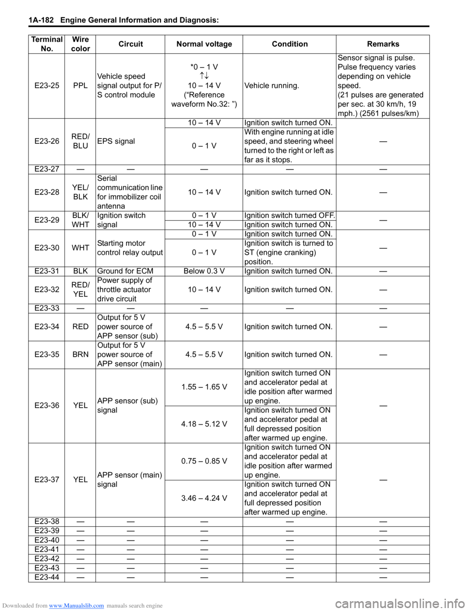
E23-25 PPLVehicle speed
signal output for P/
S control module *0 – 1 V
↑↓
10 – 14 V
(“Reference
waveform No.32: ”) Vehicle running. Sensor signal is pulse.
Pulse frequency varies
depending on vehicle
speed.
(21 pulses are generated
per sec. at 30 km/h, 19
mph.) (2561 pulses/km)
E23-26 RED/
BLU EPS signal 10 – 14 V Ignition switch turned ON.
—
0 – 1 V With engine running at idle
speed, and steering wheel
turned to the right or left as
far as it stops.
E23-27 — — — — —
E23-28 YEL/
BLK Serial
communication line
for immobilizer coil
antenna
10 – 14 V Ignition switch turned ON. —
E23-29 BLK/
WHT Ignition switch
signal 0 – 1 V Ignition switch turned OFF.
—
10 – 14 V Ignition switch turned ON.
E23-30 WHT Starting motor
control relay output 0 – 1 V Ignition switch turned ON.
—
0 – 1 V Ignition switch is turned to
ST (engine cranking)
position.
E23-31 BLK Ground for ECM Below 0.3 V Ignition switch turned ON. —
E23-32 RED/
YEL Power supply of
throttle actuator
drive circuit
10 – 14 V Ignition switch turned ON. —
E23-33 — — — — —
E23-34 RED Output for 5 V
power source of
APP sensor (sub) 4.5 – 5.5 V Ignition switch turned ON. —
E23-35 BRN Output for 5 V
power source of
APP sensor (main) 4.5 – 5.5 V Ignition switch turned ON. —
E23-36 YEL APP sensor (sub)
signal 1.55 – 1.65 V
Ignition switch turned ON
and accelerator pedal at
idle position after warmed
up engine.
—
4.18 – 5.12 V Ignition switch turned ON
and accelerator pedal at
full depressed position
after warmed up engine.
E23-37 YEL APP sensor (main)
signal 0.75 – 0.85 V
Ignition switch turned ON
and accelerator pedal at
idle position after warmed
up engine.
—
3.46 – 4.24 V Ignition switch turned ON
and accelerator pedal at
full depressed position
after warmed up engine.
E23-38 — — — — —
E23-39 — — — — —
E23-40 — — — — —
E23-41 — — — — —
E23-42 — — — — —
E23-43 — — — — —
E23-44 — — — — —
Terminal
No. Wire
color Circuit Normal voltage Condition Remarks
Page 243 of 1496
Downloaded from www.Manualslib.com manuals search engine Engine General Information and Diagnosis: 1A-193
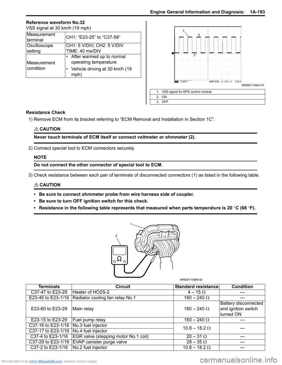
Reference waveform No.32
VSS signal at 30 km/h (19 mph)
Resistance Check1) Remove ECM from its bracket referring to “ECM Removal and Installation in Section 1C”.
CAUTION!
Never touch terminals of ECM itself or connect voltmeter or ohmmeter (2).
2) Connect special tool to ECM connectors securely.
NOTE
Do not connect the other connector of special tool to ECM.
3) Check resistance between each pair of terminals of disconnected connectors (1) as listed in the following table.
CAUTION!
• Be sure to connect ohmmeter probe from wire harness side of coupler.
• Be sure to turn OFF ignition switch for this check.
• Resistance in the following table represents that measured when parts temperature is 20 °C (68 °F).
Measurement
terminal CH1: “E23-25” to “C37-58”
Oscilloscope
setting CH1: 5 V/DIV, CH2: 5 V/DIV
TIME: 40 ms/DIV
Measurement
condition • After warmed up to normal
operating temperature
• Vehicle driving at 30 km/h (19 mph)
1. VSS signal for EPS control module
2. ON
3. OFF
I6RS0C110047-01
1
2
I4RS0A110086-02
Terminals CircuitStandard resistance Condition
C37-47 to E23-29 Heater of HO2S-2 4 – 15 Ω—
E23-46 to E23-1/16 Radiator cooling fan relay No.1 160 – 240 Ω —
E23-60 to E23-29 Main relay 160 – 240 ΩBattery disconnected
and ignition switch
turned ON
E23-15 to E23-29 Fuel pump relay 160 – 240 Ω —
C37-16 to E23-1/16 No.3 fuel injector 10.8 – 18.2 Ω —
C37-17 to E23-1/16 No.4 fuel injector
C37-4 to E23-1/16 EGR valve (st epping motor No.1 coil) 20 – 31 Ω —
C37-29 to E23-1/16 EVAP canister purge valve 28 – 35 Ω —
C37-2 to E23-1/16 No.2 fuel injector 10.8 – 18.2 Ω—
Page 244 of 1496
Downloaded from www.Manualslib.com manuals search engine 1A-194 Engine General Information and Diagnosis:
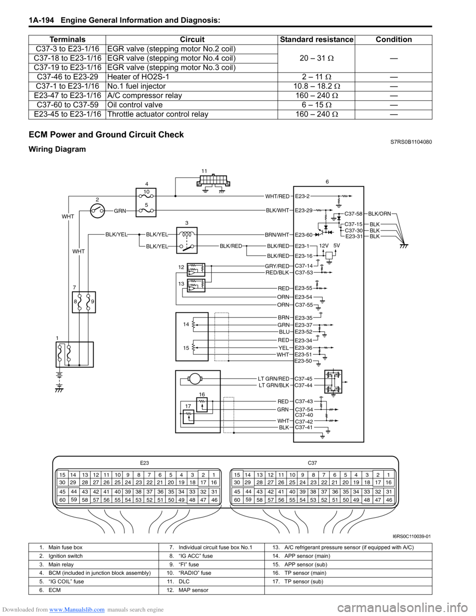
ECM Power and Ground Circuit CheckS7RS0B1104080
Wiring DiagramC37-3 to E23-1/16 EGR valve
(stepping motor No.2 coil)
20 – 31 Ω —
C37-18 to E23-1/16 EGR valv e (stepping motor No.4 coil)
C37-19 to E23-1/16 EGR valv e (stepping motor No.3 coil)
C37-46 to E23-29 Heater of HO2S-1 2 – 11 Ω—
C37-1 to E23-1/16 No.1 fuel injector 10.8 – 18.2 Ω —
E23-47 to E23-1/16 A/C compressor relay 160 – 240 Ω —
C37-60 to C37-59 Oil control valve 6 – 15 Ω —
E23-45 to E23-1/16 Throttle actuator control relay 160 – 240 Ω —
Terminals
CircuitStandard resistance Condition
E23 C37
34
1819
567
1011
17
20
47 46
495051
2122
52 16
25 9
24
14
29
55
57 54 53
59
60 58 2
262728
15
30
56 4832 31
34353637
40
42 39 38
44
45 43 41 331
1213
238
34
1819
567
1011
17
20
47 46
495051
2122
52 16
25 9
24
14
29
55
57 54 53
59
60 58 2
262728
15
30
56 4832 31
34353637
40
42 39 38
44
45 43 41 331
1213
238
BLK/RED
BLK/REDBLK/RED
BLK/YELBLK/YEL
BLK/YEL
GRN
BRN/WHT
12V
5VE23-1
E23-60
E23-16
WHT 2
4
11
6
3
12
13 14
7
1
16
17
89
15
10
5
WHT/REDE23-2
C37-58
C37-15C37-30
BLK/ORN
BLKBLKE23-31BLK
WHT
GRY/REDRED/BLK
ORN
C37-14C37-53
C37-55E23-54
REDE23-55
GRNBRN
BLU
REDYELWHT
E23-35E23-37E23-52
E23-51
E23-34E23-36
E23-50
LT GRN/REDLT GRN/BLKC37-45C37-44
C37-43
C37-54C37-40C37-42C37-41
RED
GRN
WHTBLK
ORN
BLK/WHTE23-29
I6RS0C110039-01
1. Main fuse box 7. Individual circuit fuse box No.1 13. A/C refrigerant pressure sensor (if equipped with A/C)
2. Ignition switch 8. “IG ACC” fuse14. APP sensor (main)
3. Main relay 9. “FI” fuse15. APP sensor (sub)
4. BCM (included in junction block assembly) 10. “RADIO” fuse 16. TP sensor (main)
5. “IG COIL” fuse 11. DLC17. TP sensor (sub)
6. ECM 12. MAP sensor
Page 245 of 1496
Downloaded from www.Manualslib.com manuals search engine Engine General Information and Diagnosis: 1A-195
Circuit Description
When the ignition switch is turned ON, the main relay turns ON (the contact point closes) and the main power is
supplied to ECM.
Troubleshooting
NOTE
When measuring circuit voltage, resistance and/or pulse signal at ECM connector, connect the special
tool to ECM and/or the ECM connectors referri ng to “Inspection of ECM and Its Circuits”.
StepAction YesNo
1 Circuit fuse check
1) Disconnect connectors from ECM with ignition switch
turned OFF.
2) Check for proper connection to ECM connector at “E23- 2”, “E23-29”, “E23-60”, “E23-1”, “E23-16”, “E23-31”,
“C37-58”, “C37-15” and “C37-30” terminals.
3) If OK, check “RADIO” fuse and “IG COIL” fuse for blowing.
Are “RADIO” fuse and “IG COIL” fuse in good condition? Go to Step 2.
Replace fuse (s) and
check for short in
circuits connected to
fuse(s).
2 Power supply circuit check
1) Measure voltage between “E23-2” terminal of ECM
connector and body ground.
Is voltage 10 – 14 V? Go to Step 3.
“WHT/RED” or “WHT”
wire is open circuit.
3 Ignition signal check
1) Turn ignition switch to ON position.
2) Measure voltage between “E23-29” terminal of ECM
connector and body ground.
Is voltage 10 – 14 V? Go to Step 4.
“BLK/WHT” or “GRN”
wire is open circuit.
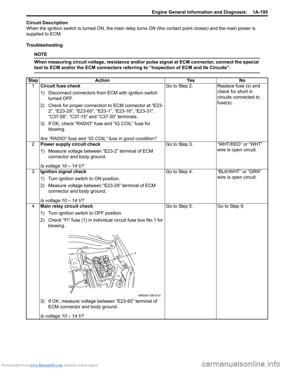
4 Main relay circuit check
1) Turn ignition switch to OFF position.
2) Check “FI” fuse (1) in indivi dual circuit fuse box No.1 for
blowing.
3) If OK, measure voltage between “E23-60” terminal of ECM connector and body ground.
Is voltage 10 – 14 V? Go to Step 5.
Go to Step 9.
1
I4RS0A110016-01
Page 248 of 1496
Downloaded from www.Manualslib.com manuals search engine 1A-198 Engine General Information and Diagnosis:
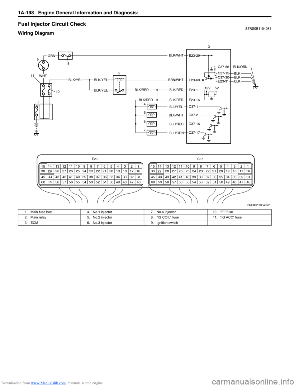
Fuel Injector Circuit CheckS7RS0B1104081
Wiring Diagram
BLK/WHTBLK/RED
BLK/RED
WHTBLK/YELBLK/YEL
BLK/YEL
GRN
BRN/WHT
12V 5V
9
2
8 3E23-29
E23-1
E23-60
10
11
E23
C37
34
1819
567
1011
17
20
47 46
495051
2122
52 16
25 9
24
14
29
55
57 54 53
59
60 58 2
262728
15
30
56 4832 31
34353637
40
42 39 38
44
45 43 41 331
1213
238
34
1819
567
1011
17
20
47 46
495051
2122
52 16
25 9
24
14
29
55
57 54 53
59
60 58 2
262728
15
30
56 4832 31
34353637
40
42 39 38
44
45 43 41 331
1213
238
C37-1
C37-2
C37-16
C37-17
BLK/REDBLK/RED
BLU/YEL
BLU/RED
BLU/ORN
BLU/WHT
E23-16
4
5
6
71
C37-58
C37-15 C37-30 E23-31
BLK/ORN
BLKBLKBLK
I6RS0C110040-01
1. Main fuse box 4. No.1 injector 7. No.4 injector10. “FI” fuse
2. Main relay 5. No.2 injector 8. “IG COIL” fuse 11. “IG ACC” fuse
3. ECM 6. No.3 injector 9. Ignition switch