Page 250 of 1496
Downloaded from www.Manualslib.com manuals search engine 1A-200 Engine General Information and Diagnosis:
Fuel Pump and Its Circuit CheckS7RS0B1104082
Wiring Diagram
E23-1
E23-60
E23-15
BRN/WHT
BLK/REDBLK/YEL
BLK/YEL
BLK/RED
E23-29BLK/WHT
GRN/WHT
BLK/WHT
BLK/WHT
PNK
BLK
WHT
GRN
C37-58
C37-15
C37-30
BLK/ORN
BLK
BLKE23-31BLK
78
9 6
4 3
2 5
E23
C37
34
1819
567
1011
17
20
47 46
495051
2122
52 16
25 9
24
14
29
55
57 54 53
59
60 58 2
262728
15
30
56 48 32 31
34353637
40
42 39 38
44
45 43 41 331
1213
238
34
1819
567
1011
17
20
47 46
495051
2122
52 16
25 9
24
14
29
55
57 54 53
59
60 58 2
262728
15
30
56 4832 31
34353637
40
42 39 38
44
45 43 41 331
1213
238
BLK/YEL
1
E23-16BLK/RED
BLK/RED
I6RS0C110041-01
1. Main fuse box 4. Fuel pump relay 7. Ignition switch
2. Main relay 5. Fuel pump 8. “FI” fuse
3. ECM 6. “IG COIL” fuse 9. “IG ACC” fuse
Page 259 of 1496

Downloaded from www.Manualslib.com manuals search engine Engine General Information and Diagnosis: 1A-209
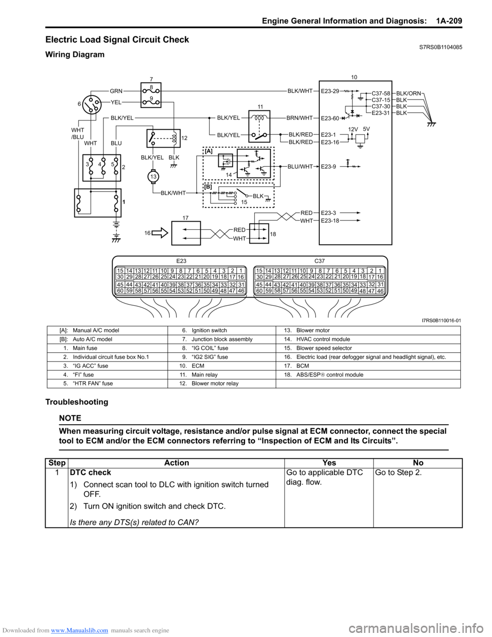
Electric Load Signal Circuit CheckS7RS0B1104085
Wiring Diagram
Troubleshooting
NOTE
When measuring circuit voltage, resistance and/or pulse signal at ECM connector, connect the special
tool to ECM and/or the ECM connectors referri ng to “Inspection of ECM and Its Circuits”.
BLK/WHT
BLK/RED
WHT
BRN/WHT
12V5V
11
BLK/YELBLK/YEL
BLK/YEL
BLKBLKBLK
BLK/ORN
10
18
17
BLU/WHT
15
WHTRED
43
YEL
5
13
BLK/WHT
BLKBLK/YEL
GRN
WHT
/BLU
BLU
16
2
6
7
12
8
9
BLK
WHT
RED
E23-29
E23-60
E23-1E23-16
E23-9
E23-3E23-18
C37-58C37-15
E23-31C37-30
BLK/RED
[A]
[B]
E23 C37
34
1819
567
10
11
17
20
47 46
495051
2122
52 16
25 9
24
14
29
5557 54 53
59
60 58 2
262728
15
30
56 4832 31
34353637
4042 39 38
44
45 43 41 331
1213
238
34
1819
567
10
11
17
20
47 46
495051
2122
52 16
25 9
24
14
29
5557 54 53
59
60 58 2
262728
15
30
56 4832 31
34353637
4042 39 38
44
45 43 41 331
12
13
238
1
14
I7RS0B110016-01
[A]: Manual A/C model
6. Ignition switch13. Blower motor
[B]: Auto A/C model 7. Junction block assembly14. HVAC control module
1. Main fuse 8. “IG COIL” fuse15. Blower speed selector
2. Individual circuit fuse box No.1 9. “IG2 SIG” fuse16. Electric load (rear defogger signal and headlight signal), etc.
3. “IG ACC” fuse 10. ECM17. BCM
4. “FI” fuse 11. Main relay18. ABS/ESP® control module
5. “HTR FAN” fuse 12. Blower motor relay
StepAction YesNo
1 DTC check
1) Connect scan tool to DLC with ignition switch turned
OFF.
2) Turn ON ignition switch and check DTC.
Is there any DTS(s) related to CAN? Go to applicable DTC
diag. flow.
Go to Step 2.
Page 394 of 1496

Downloaded from www.Manualslib.com manuals search engine 1H-2 Ignition System:
Schematic and Routing Diagram
Ignition System Wiring Circuit DiagramS7RS0B1802001
E23-60
E23-29 12V 5V
5V
E23-1
E23-16
BLK/WHT
BLK/RED
BLK/RED BLK/RED
BLK/YELBLK/YEL
BLK/YEL
GRN
BLKWHT
WHT
BRN/WHT
BLK/ORN
BLK
BLK
C37-20
BLK/RED
PNK
5V
C37-21
BLK/WHT
7
3 4
1
12 5
6
2
11
8
9
10
GRN/YEL
GRN/WHT
C37-6
C37-5 5V
5V
RED/YEL
C37-58
C37-15
C37-30
E23
C37
34
1819
567
1011
17
20
47 46
495051
2122
52 16
25 9
24
14
29
55
57 54 53
59
60 58 2
262728
15
30
56 4832 31
34353637
40
42 39 38
44
45 43 41 331
1213
238
34
1819
567
1011
17
20
47 46
495051
2122
52 16
25 9
24
14
29
55
57 54 53
59
60 58 2
262728
15
30
56 4832 31
34353637
40
42 39 38
44
45 43 41 331
1213
238
13
14
15
16
17
50A50A80A
BLK/ORN
E23-31 BLK
I4RS0B180001-01
1. Ignition switch 7. No.1 spark plug 13. Individual circuit fuse box
No.1
2. Main relay 8. No.2 spark plug 14. “IG ACC” fuse
3. Ignition coil assembly for No.1 and No.4 spark plugs 9. No.3 spark plug 15. “FI” fuse
4. Ignition coil assembly for No.2 and No.3 spark plugs 10. No.4 spark plug 16. Junction block assembly
5. CMP sensor 11. Sensed information (MAP sensor, ECT sensor, MAF and IAT
sensor, TP sensor, Knock sensor, VSS, Electric load signal,
Engine start signal) 17. “IG COIL” fuse
6. CKP sensor 12. Battery fuse box