Page 968 of 1496
Downloaded from www.Manualslib.com manuals search engine 7B-20 Air Conditioning System: Manual Type
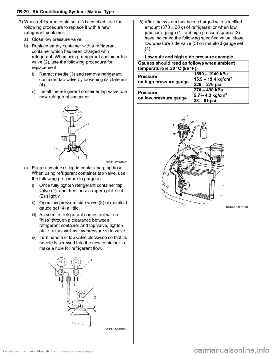
7) When refrigerant container (1) is emptied, use the following procedure to replace it with a new
refrigerant container.
a) Close low pressure valve.
b) Replace empty container with a refrigerant container which has been charged with
refrigerant. When using refrigerant container tap
valve (2), use the following procedure for
replacement.
i) Retract needle (3) and remove refrigerant container tap valve by loosening its plate nut
(4).
ii) Install the refrigerant container tap valve to a new refrigerant container.
c) Purge any air existing in center charging hose. When using refrigerant container tap valve, use
the following procedure to purge air.
i) Once fully tighten refrigerant container tap valve (1), and then loosen (open) plate nut
(2) slightly.
ii) Open low pressure side valve (3) of manifold
gauge set (4) a little.
iii) As soon as refrigerant comes out with a “hiss” through a clearance between
refrigerant container and tap valve, tighten
plate nut as well as low pressure side valve.
iv) Turn handle of tap valve clockwise so that its needle is screwed into the new container to
make a hole for refrigerant flow. 8) After the system has been charged with specified
amount (370 ± 20 g) of refrigerant or when low
pressure gauge (1) and high pressure gauge (2)
have indicated the following specified value, close
low pressure side valve (3) on manifold gauge set
(4).
Low side and high side pressure example
I2RH01720018-01
I2RH01720019-01
Gauges should read as follows when ambient
temperature is 30 °C (86 °F).
Pressure
on high pressure gauge 1590 – 1940 kPa
15.9 – 19.4 kg/cm
2
226 – 276 psi
Pressure
on low pressure gauge 270 – 430 kPa
2.7 – 4.3 kg/cm
2
38 – 61 psi
1
3 42
I4RS0A720016-01
Page 1046 of 1496
Downloaded from www.Manualslib.com manuals search engine 8B-8 Air Bag System:
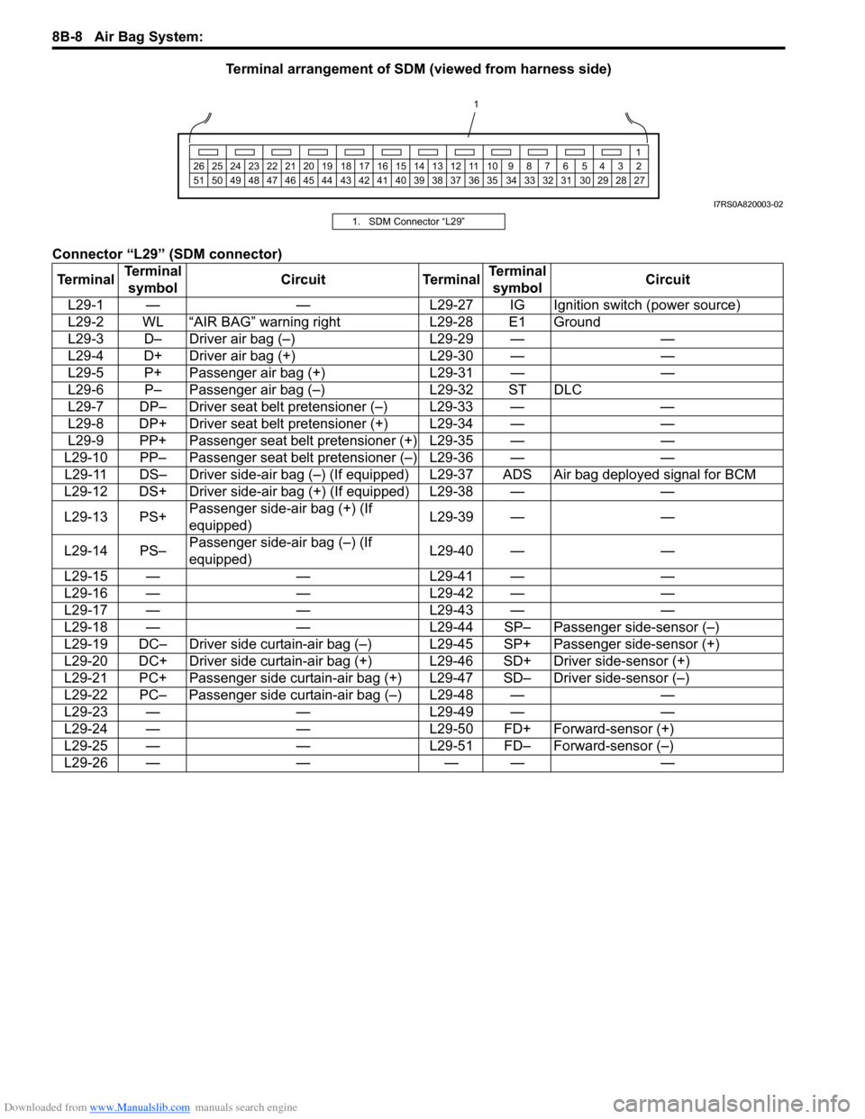
Terminal arrangement of SDM (viewed from harness side)
Connector “L29” (SDM connector)
1 2345678910
11
1213141516171819202122232425
272829303132333435363738394041424344454647484950
1
26
51
I7RS0A820003-02
1. SDM Connector “L29”
Terminal Terminal
symbol Circuit Terminal Terminal
symbol Circuit
L29-1 — — L29-27 IG Ignition switch (power source)
L29-2 WL “AIR BAG” warning right L29-28 E1 Ground
L29-3 D– Driver air bag (–) L29-29 — —
L29-4 D+ Driver air bag (+) L29-30 — —
L29-5 P+ Passenger air bag (+) L29-31 — —
L29-6 P– Passenger air bag (–) L29-32 ST DLC
L29-7 DP– Driver seat belt pretensioner (–) L29-33 — —
L29-8 DP+ Driver seat belt pretensioner (+) L29-34 — —
L29-9 PP+ Passenger seat belt pretensioner (+) L29-35 — —
L29-10 PP– Passenger seat belt pretensioner (–) L29-36 — — L29-11 DS– Driver side-air bag (–) (If equipped ) L29-37 ADS Air bag deployed signal for BCM
L29-12 DS+ Driver side-air bag (+) (If equipped) L29-38 — —
L29-13 PS+ Passenger side-air bag (+) (If
equipped) L29-39 — —
L29-14 PS– Passenger side-air bag (–) (If
equipped) L29-40 — —
L29-15 — — L29-41 — —
L29-16 — — L29-42 — —
L29-17 — — L29-43 — —
L29-18 — — L29-44 SP– Passenger side-sensor (–)
L29-19 DC– Driver side curtain-air bag (–) L29-45 SP+ Passenger side-sensor (+)
L29-20 DC+ Driver side curtain-air bag (+) L29-46 SD+ Driver side-sensor (+)
L29-21 PC+ Passenger side curtain-air bag (+) L29-47 SD– Driver side-sensor (–)
L29-22 PC– Passenger side curtain-air bag (–) L29-48 — —
L29-23 — — L29-49 — —
L29-24 — — L29-50 FD+ Forward-sensor (+)
L29-25 — — L29-51 FD– Forward-sensor (–)
L29-26 — — — — —
Page 1173 of 1496
Downloaded from www.Manualslib.com manuals search engine Wiring Systems: 9A-2
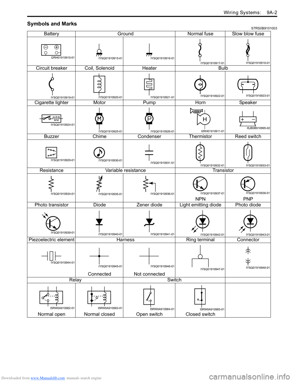
Symbols and MarksS7RS0B9101003
BatteryGroundNormal fuse Slow blow fuse
Circuit breaker Coil, SolenoidHeater Bulb
Cigarette lighter MotorPump HornSpeaker
Buzzer ChimeCondenser Thermistor Reed switch
Resistance Variable resistance Transistor
NPN PNP
Photo transistor DiodeZener diode L ight emitting diode Photo diode
Piezoelectric element Harness Ring terminal Connector
Connected Not connected
Relay Switch
Normal open Normal closed Open switch Closed switch
I2RH01910910-01IYSQ01910915-01IYSQ01910916-01
IYSQ01910917-01IYSQ01910918-01
IYSQ01910919-01IYSQ01910920-01IYSQ01910921-01IYSQ01910922-01IYSQ01910923-01
IYSQ01910924-01
IYSQ01910925-01IYSQ01910926-01
H
I2RH01910911-01I5JB0B910995-02
IYSQ01910929-01IYSQ01910930-01IYSQ01910931-01IYSQ01910932-01IYSQ01910933-01
IYSQ01910934-01IYSQ01910935-01IYSQ01910936-01IYSQ01910937-01IYSQ01910938-01
IYSQ01910939-01IYSQ01910940-01IYSQ01910941-01IYSQ01910942-01IYSQ01910943-01
IYSQ01910944-01IYSQ01910945-01IYSQ01910946-01IYSQ01910947-01IYSQ01910948-01
I5RW0A910982-01I5RW0A910983-01I5RW0A910984-01I5RW0A910985-01
Page 1217 of 1496
Downloaded from www.Manualslib.com manuals search engine Wiring Systems: 9A-46
A-1 Cranking System Circuit DiagramS7RS0B910E002
Starting motorrelay
W
"A-5"
ECM
P
R N D2LTransaxle
range sensor
C28
E741
4
E31
C231C241
Starting motor
MOFF ON
BLK
1
BLK/GRY
C311
Battery
E24
C361
RED
Individual circuit
fuse box (No.1)
10
30A
36
10A
WHTWHT
M/T
IF EQPD
E24
C361
J/B
A/T
E4110
13
2
4
RED/WHT
2 ST MOT
ST SIG
YEL/GRN
YG
"A-5"
ECM
GRN/WHT
G212
YEL/GRN
YEL/GRN
YEL
YEL/GRN
YEL
YEL
G324
+B1
LOCK
ACC
ON
ST ACC IG1 IG2
STOUT
IN
+B2
21CPP
switch
2
I7RS0B910940-01
Page 1276 of 1496
Downloaded from www.Manualslib.com manuals search engine 9A-105 Wiring Systems:
E18E19E20E21 E22
IF EQPD
E23 E24 (TO C36) E25E26
RHD
E26 E27E27E28 E29E30
LHD RHD LHD
E31 E32E33E34 E35E36
E37 (TO G35) E38 (TO G36) E39E40
E41 E42E43
E44 (TO L03) E45 (TO L02) E46E47
E48 (TO E50) E49 E50 (TO E48) E51E52
21
MCONF020198-01
12
MCONF020156-01
21
MCONF020197-01
12
3
MCONF030101-01
1
2
MCONF020013-01
123456
202116171819
78910
22232425
12
2726
13
28
313233343536
505146474849
37383940
52535455
11
41
56
42
57
43
58
1415
2930
44
60
45
59
MCONF600003-01
34
7
2
68910
121314
1716
1
5
11
15181920
MCONM200005-01
21
MCONM020043-01
21
MCONF020114-01
1
2
MCONF020170-01
21
MCONF020201-01
1
2
MCONF020169-01
1
2
345
MCONF050015-01
1
2
345
MCONF050015-01
1
2
345
MCONF050015-01
1
2
34
MCONF040004-01
1
2
34
MCONF040004-01
1
2
34
MCONF040004-01
1
2
34
MCONF040004-01
1
2
34
MCONF040004-01
1
2
34
MCONF040004-01
381371251015
14914
2611
MCONM150001-01
54 32 167910
20 19 18 17 16 15 14 13 12 118
MCONM200008-01
1 234
5 678 910
MCONF100003-01
21
MCONF020202-01
6
5
4
3
2
17
11
10
9
8 15
14
13
12 16
MCONF160034-01
CC
AABB
DE
DD
EE
MCONF120059-01
CC
AABB
DE
DD
EE
MCONF120059-01
12
34
MCONF040095-0110 1
6111415 16 171213
2
734
85
9
MCONF170009-01
12567
8
9 1011121314
34
MCONF140012-01
12
34
MCONF040009-01
21
7654
3
8
MCONM080012-01
1
2
MCONF020203-01
2
51
47 6
8
3
MCONF080014-01
1
2
MCONF020204-01
10
11 12 13 14 15 16 17 18 19 123456789
20
MCONF200021-01
Page 1277 of 1496
Downloaded from www.Manualslib.com manuals search engine Wiring Systems: 9A-106
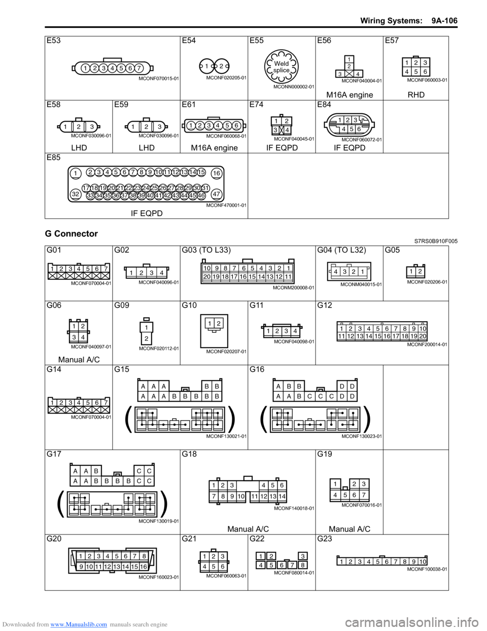
G ConnectorS7RS0B910F005
E53E54E55 E56E57
M16A engine RHD
E58 E59E61E74 E84
LHD LHD M16A engine IF EQPD IF EQPD
E85
IF EQPD
G01 G02G03 (TO L33) G04 (TO L32) G05
G06 G09G10G11G12
Manual A/C
G14 G15 G16
G17 G18G19
Manual A/C Manual A/C
G20 G21G22G23
1234567
MCONF070015-01
12
MCONF020205-01
Weld
splice
MCONN000002-01
1
2
34
MCONF040004-01
123
46 5
MCONF060003-01
1 23
MCONF030096-01
123
MCONF030096-01
1234 56
MCONF060068-01
1
34
2
MCONF040045-01
2
5
46
13
MCONF060072-01
21
3247
163451213141567891011
3334353643444546373839404142181719202128293031222324252627
MCONF470001-01
1234567
MCONF070004-01
1234
MCONF040096-01
54 32 167910
20 19 18 17 16 15 14 13 12 118
MCONM200008-01
12
34
MCONM040015-01
12
MCONF020206-01
12
34
MCONF040097-01
1
2
MCONF020112-01
21
MCONF020207-01
1234
MCONF040098-01
125678911 12 13 14 15 16 17 18 1910
2034
MCONF200014-01
1234567
MCONF070004-01
AAA BB
AAA B
BB
BB
( )
MCONF130021-01
ABB DD
AAB D
CC
CD
( )
MCONF130023-01
AAB CC
AAB C
BB
BC
( )
MCONF130019-01
123
78910
456
11121314
MCONF140018-01
3
7654
21
MCONF070016-01
1234567 8
9 10111213141516
MCONF160023-01
3
21
654
MCONF060063-01
2
51
47 6
8
3
MCONF080014-01
12345678910MCONF100038-01
Page 1318 of 1496
Downloaded from www.Manualslib.com manuals search engine 9D-1 Wipers / Washers:
Body, Cab and Accessories
Wipers / Washers
Diagnostic Information and Procedures
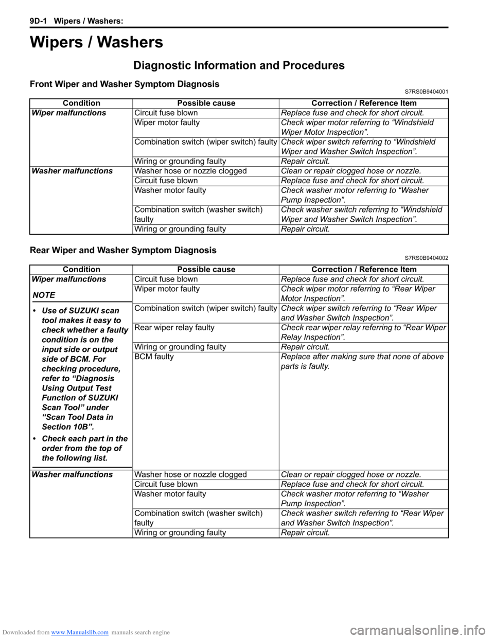
Front Wiper and Washer Symptom DiagnosisS7RS0B9404001
Rear Wiper and Washer Symptom DiagnosisS7RS0B9404002
ConditionPossible cause Correction / Reference Item
Wiper malfunctions Circuit fuse blown Replace fuse and check for short circuit.
Wiper motor faulty Check wiper motor referring to “Windshield
Wiper Motor Inspection”.
Combination switch (wiper switch) faulty Check wiper switch referring to “Windshield
Wiper and Washer Switch Inspection”.
Wiring or grounding faulty Repair circuit.
Washer malfunctions Washer hose or nozzle clogged Clean or repair clogged hose or nozzle.
Circuit fuse blown Replace fuse and check for short circuit.
Washer motor faulty Check washer motor referring to “Washer
Pump Inspection”.
Combination switch (washer switch)
faulty Check washer switch referring to “Windshield
Wiper and Washer Switch Inspection”.
Wiring or grounding faulty Repair circuit.
ConditionPossible cause Correction / Reference Item
Wiper malfunctions
NOTE
• Use of SUZUKI scan tool makes it easy to
check whether a faulty
condition is on the
input side or output
side of BCM. For
checking procedure,
refer to “Diagnosis
Using Output Test
Function of SUZUKI
Scan Tool” under
“Scan Tool Data in
Section 10B”.
• Check each part in the order from the top of
the following list.
Circuit fuse blown Replace fuse and check for short circuit.
Wiper motor faulty Check wiper motor referring to “Rear Wiper
Motor Inspection”.
Combination switch (wiper switch) faulty Check wiper switch referring to “Rear Wiper
and Washer Switch Inspection”.
Rear wiper relay faulty Check rear wiper relay referring to “Rear Wiper
Relay Inspection”.
Wiring or grounding faulty Repair circuit.
BCM faulty Replace after making sure that none of above
parts is faulty.
Washer malfunctions Washer hose or nozzle clogged Clean or repair clogged hose or nozzle.
Circuit fuse blown Replace fuse and check for short circuit.
Washer motor faulty Check washer motor referring to “Washer
Pump Inspection”.
Combination switch (washer switch)
faulty Check washer switch referring to “Rear Wiper
and Washer Switch Inspection”.
Wiring or grounding faulty Repair circuit.
Page 1319 of 1496
Downloaded from www.Manualslib.com manuals search engine Wipers / Washers: 9D-2
Repair Instructions
Wipers and Washers ComponentsS7RS0B9406001
NOTE
Below figure shows left-hand steering vehicle. For right-hand steering vehicle, parts with (*) are
installed at the opposite side.
11 5
6
(b)
(b)
(c)
*12
13 14
*14
14[A]
(a)
(a)
(b)
(b)
*3*1
*2
*1
*4
(b)
*2
(d)
7 9
10
10
10
11
118
I5RS0C940006-01