2006 SUZUKI SWIFT 940
[x] Cancel search: 940Page 318 of 1496
Downloaded from www.Manualslib.com manuals search engine 1D-33 Engine Mechanical:
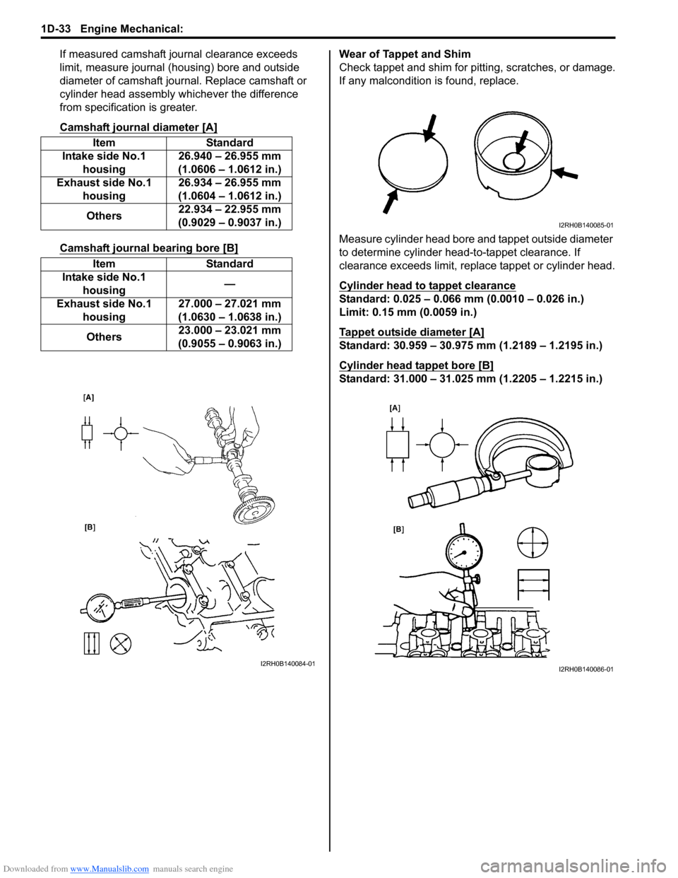
If measured camshaft journal clearance exceeds
limit, measure journal (housing) bore and outside
diameter of camshaft journal. Replace camshaft or
cylinder head assembly whichever the difference
from specification is greater.
Camshaft journal diameter [A]
Camshaft journal bearing bore [B]
Wear of Tappet and Shim
Check tappet and shim for pitting, scratches, or damage.
If any malcondition is found, replace.
Measure cylinder head bore and tappet outside diameter
to determine cylinder head-to-tappet clearance. If
clearance exceeds limit, replace tappet or cylinder head.
Cylinder head to tappet clearance
Standard: 0.025 – 0.066 mm (0.0010 – 0.026 in.)
Limit: 0.15 mm (0.0059 in.)
Tappet outside diameter [A]
Standard: 30.959 – 30.975 mm (1.2189 – 1.2195 in.)
Cylinder head tappet bore [B]
Standard: 31.000 – 31.025 mm (1.2205 – 1.2215 in.)
Item Standard
Intake side No.1 housing 26.940 – 26.955 mm
(1.0606 – 1.0612 in.)
Exhaust side No.1 housing 26.934 – 26.955 mm
(1.0604 – 1.0612 in.)
Others 22.934 – 22.955 mm
(0.9029 – 0.9037 in.)
Item Standard
Intake side No.1 housing —
Exhaust side No.1 housing 27.000 – 27.021 mm
(1.0630 – 1.0638 in.)
Others 23.000 – 23.021 mm
(0.9055 – 0.9063 in.)
I2RH0B140084-01
I2RH0B140085-01
I2RH0B140086-01
Page 337 of 1496
Downloaded from www.Manualslib.com manuals search engine Engine Mechanical: 1D-52
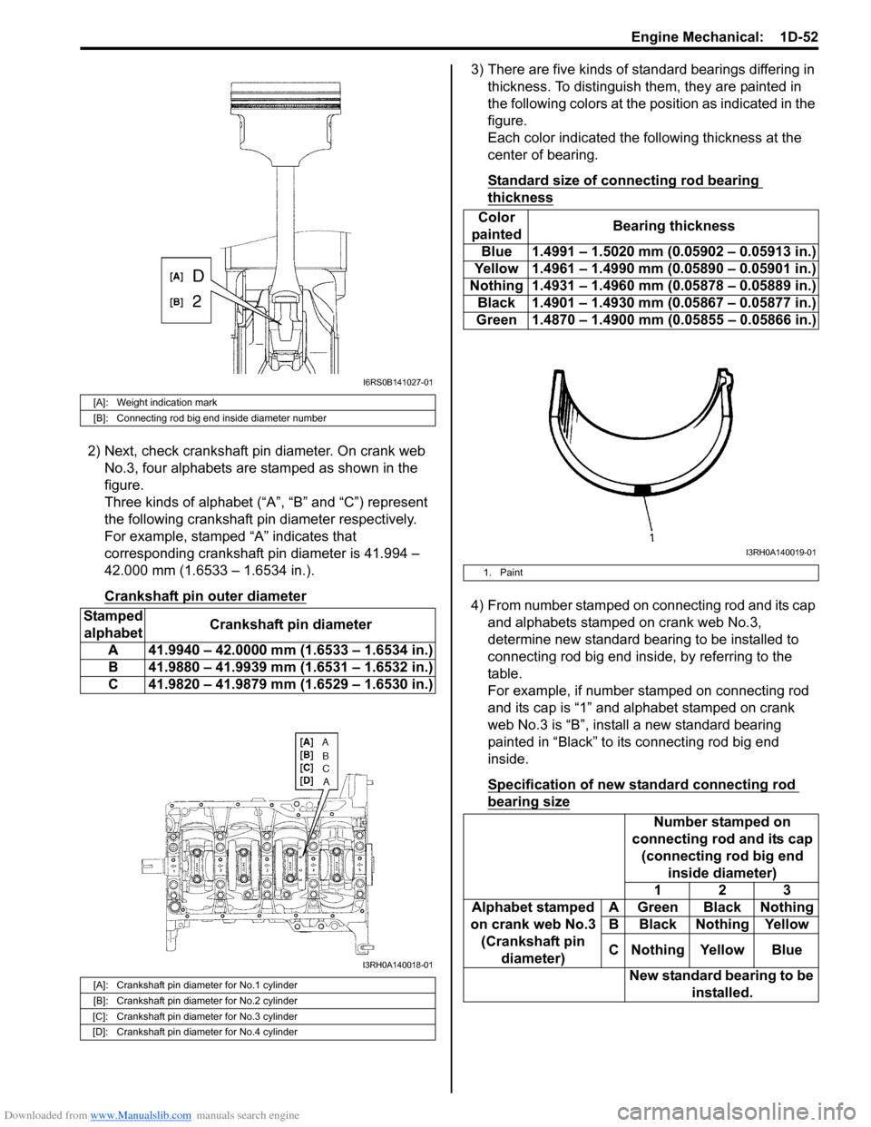
2) Next, check crankshaft pin diameter. On crank web No.3, four alphabets are stamped as shown in the
figure.
Three kinds of alphabet (“A”, “B” and “C”) represent
the following crankshaft pin diameter respectively.
For example, stamped “A” indicates that
corresponding crankshaft pin diameter is 41.994 –
42.000 mm (1.6533 – 1.6534 in.).
Crankshaft pin outer diameter
3) There are five kinds of standard bearings differing in thickness. To distinguish them, they are painted in
the following colors at the position as indicated in the
figure.
Each color indicated the following thickness at the
center of bearing.
Standard size of connecting rod bearing
thickness
4) From number stamped on connecting rod and its cap and alphabets stamped on crank web No.3,
determine new standard bearing to be installed to
connecting rod big end inside, by referring to the
table.
For example, if number stamped on connecting rod
and its cap is “1” and alphabet stamped on crank
web No.3 is “B”, install a new standard bearing
painted in “Black” to its connecting rod big end
inside.
Specification of new standard connecting rod
bearing size
[A]: Weight indication mark
[B]: Connecting rod big end inside diameter number
Stamped alphabet Crankshaft pin diameter
A 41.9940 – 42.0000 mm (1.6533 – 1.6534 in.)
B 41.9880 – 41.9939 mm (1.6531 – 1.6532 in.)
C 41.9820 – 41.9879 mm (1.6529 – 1.6530 in.)
[A]: Crankshaft pin diameter for No.1 cylinder
[B]: Crankshaft pin diameter for No.2 cylinder
[C]: Crankshaft pin diameter for No.3 cylinder
[D]: Crankshaft pin diameter for No.4 cylinder
I6RS0B141027-01
I3RH0A140018-01
Color
painted Bearing thickness
Blue 1.4991 – 1.5020 mm (0.05902 – 0.05913 in.)
Yellow 1.4961 – 1.4990 mm (0.05890 – 0.05901 in.)
Nothing 1.4931 – 1.4960 mm (0.05878 – 0.05889 in.) Black 1.4901 – 1.4930 mm (0.05867 – 0.05877 in.)
Green 1.4870 – 1.4900 mm (0.05855 – 0.05866 in.)
1. Paint
Number stamped on
connecting rod and its cap (connecting rod big end inside diameter)
123
Alphabet stamped
on crank web No.3 (Crankshaft pin diameter) A Green Black Nothing
B Black Nothing Yellow
C Nothing Yellow Blue
New standard bearing to be installed.
I3RH0A140019-01
Page 345 of 1496

Downloaded from www.Manualslib.com manuals search engine Engine Mechanical: 1D-60
Selection of Main Bearings
Standard bearing
If bearing is in malcondition, or bearing clearance is out
of specification, select a new standard bearing according
to the following procedure and install it.
1) First check journal diameter. As shown in the figure, crank web No.2 has stamped numbers.
Three kinds of numbers (“1”, “2” and “3”) represent
the following journal diameters.
Stamped numbers on crank web No.2 represent
journal diameters marked with an arrow in the figure
respectively. For example, stamped number “1”
indicates that corresponding journal diameter is
51.9940 – 52.0000 mm (2.0471 – 2.0472 in.).
Crankshaft journal diameter2) Next, check bearing cap bore diameter without bearing. On mating surface of cylinder block, five
alphabets are stamped as shown in figure.
Three kinds of alphabets (“A”, “B” and “C”) or
numbers (“1”, “2” and “3”) represent the following
cap bore diameters.
Stamped alphabets or numbers on cylinder block
represent bearing cap bore diameter marked with an
arrow in the figure respectively.
For example, stamped “A” or “1” indicates that
corresponding bearing cap bo re diameter is 56.0000
– 56.0060 mm (2.2048 – 2.2049 in.).
Crankshaft bearing cap bore
Stamped
numbers Journal diameter
1 51.9940 – 52.0000 mm
(2.0471 – 2.0472 in.)
2 51.9880 – 51.9939 mm
(2.0468 – 2.0470 in.)
3 51.9820 – 51.9879 mm
(2.0465 – 2.0467 in.)
I2RH0B140142-01
Stamped alphabet
(number) Bearing cap bore diameter (without
bearing)
A or 1 56.0000 – 56.0060 mm
(2.2048 – 2.2049 in.)
B or 2 56.0061 – 56.0120 mm
(2.2050 – 2.2051 in.)
C or 3 56.0121 – 56.0180 mm
(2.2052 – 2.2054 in.)
I2RH0B140143-01
Page 439 of 1496
Downloaded from www.Manualslib.com manuals search engine Front Suspension: 2B-6
• Tighten wheel nuts to specified torque.
Tightening torque
Wheel nut: 85 N·m (8.5 kgf-m, 61.5 lb-ft)
• After installation, confirm front wheel alignment.
Front Strut Assembly Disassembly and
Assembly
S7RS0B2206004
WARNING!
Use a regular coil spring compressor and
follow the operation procedure described in
the Instruction Manual.
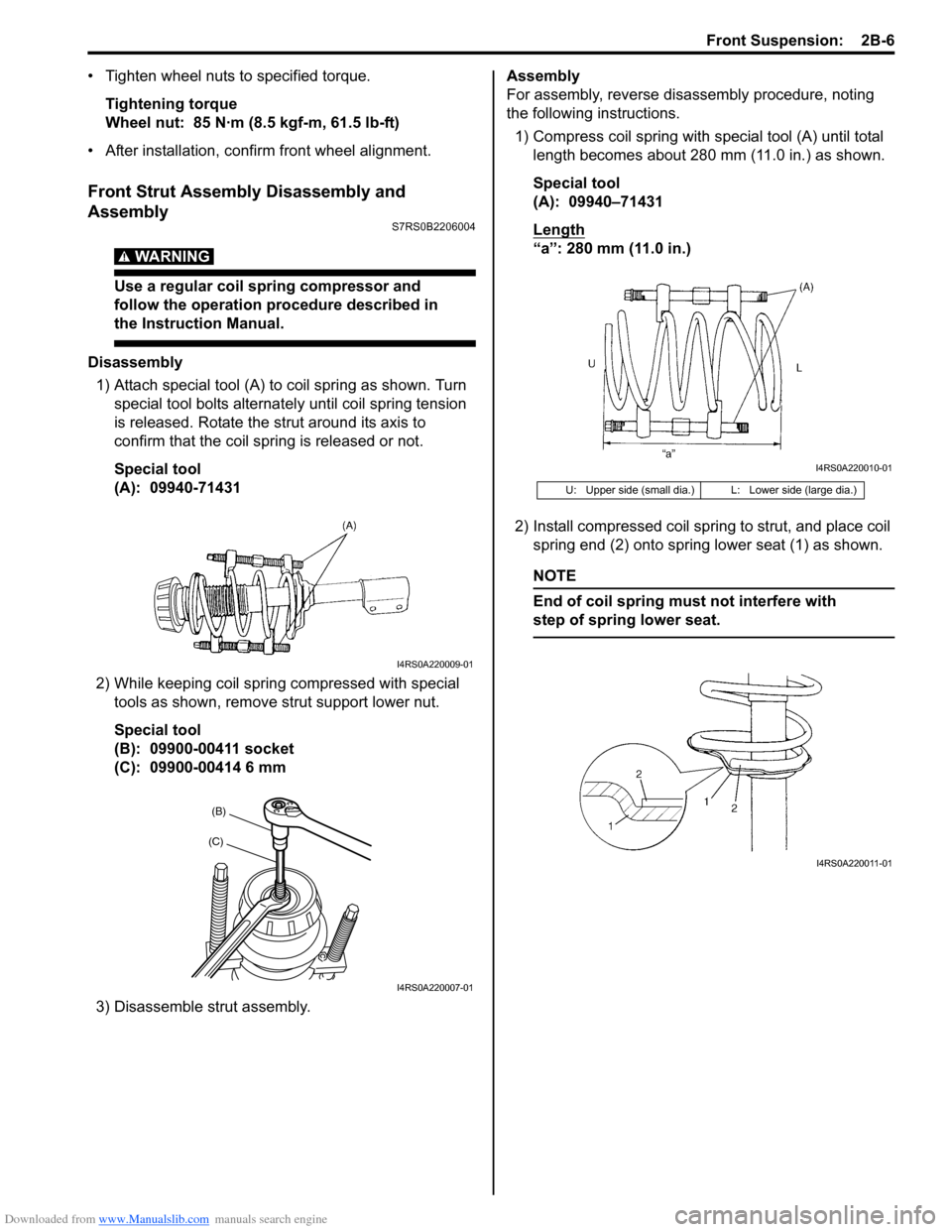
Disassembly 1) Attach special tool (A) to coil spring as shown. Turn special tool bolts alternat ely until coil spring tension
is released. Rotate the strut around its axis to
confirm that the coil spring is released or not.
Special tool
(A): 09940-71431
2) While keeping coil spring compressed with special
tools as shown, remove strut support lower nut.
Special tool
(B): 09900-00411 socket
(C): 09900-00414 6 mm
3) Disassemble strut assembly. Assembly
For assembly, reverse disassembly procedure, noting
the following instructions.
1) Compress coil spring with special tool (A) until total
length becomes about 280 mm (11.0 in.) as shown.
Special tool
(A): 09940–71431
Length
“a”: 280 mm (11.0 in.)
2) Install compressed coil spring to strut, and place coil
spring end (2) onto spring lower seat (1) as shown.
NOTE
End of coil spring must not interfere with
step of spring lower seat.
I4RS0A220009-01
(B)
(C)
I4RS0A220007-01
U: Upper side (small dia.) L: Lower side (large dia.)
I4RS0A220010-01
I4RS0A220011-01
Page 454 of 1496

Downloaded from www.Manualslib.com manuals search engine 2B-21 Front Suspension:
Special Tools and Equipment
Special ToolS7RS0B2208001
09900–0041109900–00413
Hexagon bit socket Hexagon bit (5 mm)
�) / �) / �) / �) / �)�) / �) / �)
09900–00414 09913–65810
Hexagon bit (6 mm) Crankshaft bearing puller
�) / �)�)
09913–75510 09913–75520
Bearing installer Bearing installer
�) / �)�)
09913–75821 09913–85230
Bearing installer attachment Bearing remover tool
�) / �)�)
09926–68310 09940–71431
Differential bevel pinion
bearing installer Suspension spring
compressor
�)�) / �)
09942–15511 09943–17912
Sliding hammer Wheel hub remover
�)�)
09943–76310 09951–18210
Bush remover Oil seal remover & installer
No. 2
�) / �)�)
Page 844 of 1496
Downloaded from www.Manualslib.com manuals search engine 5B-30 Manual Transmission/Transaxle:
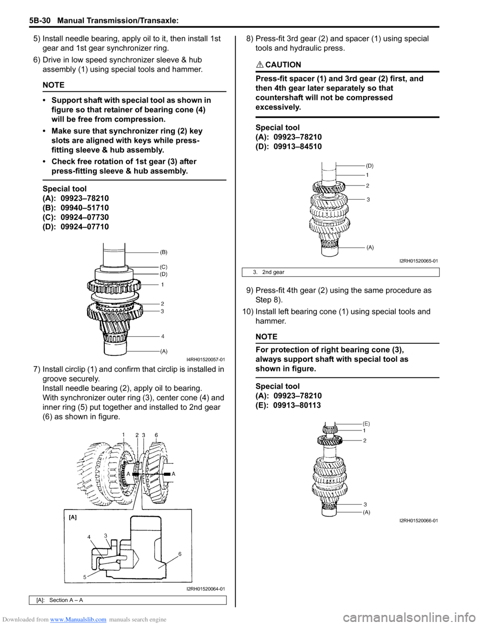
5) Install needle bearing, apply oil to it, then install 1st gear and 1st gear synchronizer ring.
6) Drive in low speed synchronizer sleeve & hub assembly (1) using special tools and hammer.
NOTE
• Support shaft with special tool as shown in figure so that retainer of bearing cone (4)
will be free from compression.
• Make sure that synchronizer ring (2) key slots are aligned with keys while press-
fitting sleeve & hub assembly.
• Check free rotation of 1st gear (3) after press-fitting sleeve & hub assembly.
Special tool
(A): 09923–78210
(B): 09940–51710
(C): 09924–07730
(D): 09924–07710
7) Install circlip (1) and confirm that circlip is installed in groove securely.
Install needle bearing (2), apply oil to bearing.
With synchronizer outer ring (3), center cone (4) and
inner ring (5) put together and installed to 2nd gear
(6) as shown in figure. 8) Press-fit 3rd gear (2) and spacer (1) using special
tools and hydraulic press.
CAUTION!
Press-fit spacer (1) and 3rd gear (2) first, and
then 4th gear later separately so that
countershaft will not be compressed
excessively.
Special tool
(A): 09923–78210
(D): 09913–84510
9) Press-fit 4th gear (2) using the same procedure as Step 8).
10) Install left bearing cone (1) using special tools and hammer.
NOTE
For protection of right bearing cone (3),
always support shaft with special tool as
shown in figure.
Special tool
(A): 09923–78210
(E): 09913–80113
[A]: Section A – A
I4RH01520057-01
I2RH01520064-01
3. 2nd gear
I2RH01520065-01
I2RH01520066-01
Page 851 of 1496

Downloaded from www.Manualslib.com manuals search engine Manual Transmission/Transaxle: 5B-37
09923–7451009923–78210
Bearing puller (20-35 mm) Bearing installer
�)�) / �) / �) / �)
09924–07710 09924–07730
Synchronizer hub installer Bearing installer
�)�)
09924–74510 09924–84510–004
Bearing and oil seal handle Bearing installer attachment
�)�)
09925–15410 09925–78210
Oil seal installer Spring pin remover (6 mm)
�)�)
09925–88210 09925–98210
Bearing puller attachment Input shaft bearing installer
�)�)
09926–27610 09927–76060
Oil seal installer Gear holder
�) / �)�) / �)
09930–30104 09940–51710
Sliding shaft Bearing installer
�) / �)�)
09941–64511 09951–16060
Bearing and oil seal remover
(30 mm Min.) Control arm bush remover
�)�)
Page 959 of 1496
Downloaded from www.Manualslib.com manuals search engine Air Conditioning System: Manual Type 7B-11
5) Warm up engine to the normal operating temperature and keep it at the specified idle speed.
6) Turn A/C switch ON, set blower speed selector at maximum speed position, temperature selector at
maximum cold position, airflow selector at face
position, and air intake switch at recirculation
position. (Confirm that A/C compressor and
condenser fans are working.)
7) Wait for ten minutes to stabilize the A/C operation.
8) Open front windows, front doors and engine hood.
9) With about 20 mm (0.8 in.) of dry bulb thermometer
(1) put right in front of center ventilation louver and a
wet and dry bulb thermometer (2) near air inlet of
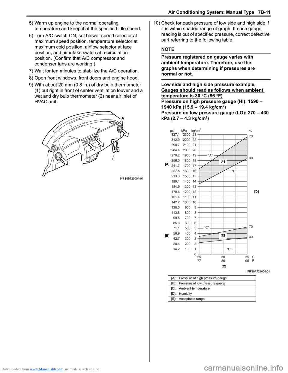
HVAC unit. 10) Check for each pressure of low side and high side if
it is within shaded range of graph. If each gauge
reading is out of specified pressure, correct defective
part referring to the following table.
NOTE
Pressure registered on gauge varies with
ambient temperature. Therefore, use the
graphs when determining if pressures are
normal or not.
Low side and high side pressure example,
Gauges should read as follows when ambient
temperature is 30 °C (86 °F)
Pressure on high pressure gauge (HI): 1590 –
1940 kPa (15.9 – 19.4 kg/cm2)
Pressure on low pressure gauge (LO): 270 – 430
kPa (2.7 – 4.3 kg/cm
2)
2
1
I4RS0B720004-01
[A]: Pressure of high pressure gauge
[B]: Pressure of low pressure gauge
[C]: Ambient temperature
[D]: Humidity [E]: Acceptable range
22
312.9 2200
0 1
2 3 30 70 30 70 %
4 5 6 7 8 9
10
11 12 13 14 15
16 17
18
19 21
298.7 2100
20
14.2 28.4 42.7 56.9 71.1 85.3 99.5
113.8 128.0 142.2
151.4
170.6
184.9 199.1
213.3 227.5
241.7
256.0
270.2
284.4
100 200 300 400 500 600 700 800 900
1000 1100 1200
1300
1400 1500 1600
1700 1800
1900
2000
25 30 35
77 86 95
psi kPa kg/cm
2
C
F
“A”
“B”
“C”
“D”
23
2300
327.1
[A]
[B]
[C][D][E]
[E]
I7RS0A721006-01