2006 SUZUKI SWIFT torque sensor
[x] Cancel search: torque sensorPage 1163 of 1496

Downloaded from www.Manualslib.com manuals search engine Air Bag System: 8B-125
Specifications
Tightening Torque SpecificationsS7RS0B8207001
NOTE
The specified tightening torque is also described in the following.
“Air Bag System Components, Wiring and Connectors Location”
Reference:
For the tightening torque of fastener not specified in this section, refer to “Fasteners Information in Section 0A”.
Special Tools and Equipment
Use of Special ToolsS7RS0B8208001
WARNING!
To avoid deployment when troubleshooting
the air bag system, do not use electrical test
equipment such as a battery powered or AC
powered voltmeter, ohmmeter, etc., or any
type of electrical equipment other than that
specified. Do not use a non-powered probe
type tester.
Instructions must be followed carefully,
otherwise personal injury may result.
You should be familiar with the tools listed under the
heading “Special Tool”. You should be able to measure
voltage and resistance. You should be familiar with
proper use of a scan tool such as Air Bag Driver /
Passenger Load Tool, Connector Test Adapter Kit and
the Digital Multimeter.
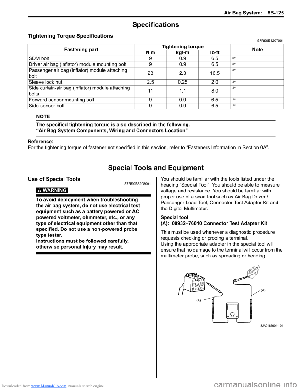
Special tool
(A): 09932–76010 Connector Test Adapter Kit
This must be used whenever a diagnostic procedure
requests checking or probing a terminal.
Using the appropriate adapter in the special tool will
ensure that no damage to the terminal will occur from the
multimeter probe, such as spreading or bending.
Fastening part
Tightening torque
Note
N ⋅mkgf-mlb-ft
SDM bolt 9 0.9 6.5 �)
Driver air bag (inflator) module mounting bolt 9 0.9 6.5 �)
Passenger air bag (inflator) module attaching
bolt 23 2.3 16.5�)
Sleeve lock nut 2.5 0.25 2.0 �)
Side curtain-air bag (inflator) module attaching
bolts 11 1.1 8.0�)
Forward-sensor mounting bolt 9 0.9 6.5 �)
Side-sensor bolt 9 0.9 6.5 �)
I3JA01820041-01
Page 1169 of 1496

Downloaded from www.Manualslib.com manuals search engine Table of Contents 9-iii
Door Switch (Front / Rear Door) Inspection ...... 9C-17
Rear End Door Switch Inspection ..................... 9C-17
Outside Air Temperature Sensor Removal and Installation (If Equipped) .......................... 9C-17
Outside Air Temperature Sensor Inspection (If Equipped) ................................................... 9C-17
Instrument Panel Removal and Installation....... 9C-18
Information Display (Clock) Removal and Installation ....................................................... 9C-19
Audio Unit Removal and In stallation ................. 9C-19
Front Speaker Removal and Installation ........... 9C-19
Rear Speaker Removal and Installation............ 9C-20
Horn Removal and Installation .......................... 9C-20
Horn Inspection ................................................. 9C-20
Horn Relay Inspection ....................................... 9C-20
Antenna Amplifier Removal and Installation ..... 9C-21
Remote Audio Control Switch Removal and Installation (If Equipped) ................................. 9C-21
Remote Audio Control Switch Inspection (If Equipped)........................................................ 9C-22
Vehicle Speed Signal Inspection (For Audio Unit) (If Equipped) ........................................... 9C-22
Specifications ..................................................... 9C-22
Tightening Torque Specifications ...................... 9C-22
Wipers / Washers............ ......................... 9D-1
Diagnostic Information and Procedures ............ 9D-1
Front Wiper and Washer Symptom Diagnosis .... 9D-1
Rear Wiper and Washer Symptom Diagnosis..... 9D-1
Repair Instructions .............................................. 9D-2 Wipers and Washers Components ..................... 9D-2
Washer Tank and Washer Pump Removal and Installation .................................................. 9D-3
Washer Pump Inspection .................................... 9D-3
Windshield Wiper Removal and Installation ........ 9D-4
Windshield Wiper Motor Inspection..................... 9D-5
Rear Wiper Removal and Installation.................. 9D-6
Rear Wiper Motor Inspection .............................. 9D-7
Windshield Wiper and Washer Switch Removal and Installation................................... 9D-7
Windshield Wiper and Washer Switch Inspection.......................................................... 9D-8
Rear Wiper and Washer Switch Removal and Installation ......................................................... 9D-9
Rear Wiper and Washer Switch Inspection......... 9D-9
Rear Wiper Relay Removal and Installation ..... 9D-10
Rear Wiper Relay Inspection ............................ 9D-10
Specifications ..................................................... 9D-10
Tightening Torque Specifications ...................... 9D-10
Glass / Windows / Mirrors.. ..................... 9E-1
General Description ............................................. 9E-1
Rear End Door Window Defogger System Description ........................................................ 9E-1
Windshield Construction ..................................... 9E-1
Diagnostic Information and Procedures ............ 9E-2 Rear End door Window Defogger Symptom Diagnosis .......................................................... 9E-2 Power Window Control System Symptom
Diagnosis .......................................................... 9E-2
Power Door Mirror Control System Symptom Diagnosis .......................................................... 9E-3
Door Mirror Heater Symptom Diagnosis (If
Equipped) .......................................................... 9E-3
Repair Instructions ........... ................................... 9E-4
Windshield Removal and In stallation .................. 9E-4
Front Door Window Components ........................ 9E-8
Front Door Glass Removal and Installation ........ 9E-8
Front Door Window Re gulator Removal and
Installation ......................................................... 9E-9
Front Door Window Regula tor Inspection ......... 9E-10
Rear Door Window Components ...................... 9E-10
Rear Door Glass Removal and Installation ....... 9E-11
Rear Door Window Regulator Removal and Installation ....................................................... 9E-12
Rear Door Window Regulato r Inspection .......... 9E-12
Rear End Door Window Components ............... 9E-13
Rear End Door Glass Removal and Installation ....................................................... 9E-13
Rear End Door Window Defogger Switch Inspection ........................................................ 9E-14
Rear End Door Window Defogger Relay Inspection ........................................................ 9E-14
Rear End Door Window Defogger Wire Inspection ........................................................ 9E-15
Rear End Door Window Defogger Wire
Repair.............................................................. 9E-15
Power Window Main Switch Inspection ............ 9E-16
Power Window Sub Switch Inspection .............. 9E-17
Door Mirror Components.. ................................. 9E-18
Door Mirror Removal and In stallation................ 9E-18
Power Door Mirror Switch Inspection ................ 9E-18
Power Door Mirror Actuator Inspection ............. 9E-19
Door Mirror Heater Switch Inspection (If Equipped) ........................................................ 9E-19
Door Mirror Heater Inspec tion (If Equipped) ..... 9E-19
Special Tools and Equipmen t ........................... 9E-19
Recommended Service Material ....................... 9E-19
Security and Locks......... ..........................9F-1
General Description ............................................. 9F-1
Key Coding Construction .................................... 9F-1
Rear End Door Opener System Description ....... 9F-1
Component Location ............ ............................... 9F-2
Power Door Lock and Keyless Entry System
Component Location ......................................... 9F-2
Diagnostic Information and Procedures ............ 9F-3 Power Door Lock System Symptom Diagnosis .......................................................... 9F-3
Power Door Lock System Operation Inspection .......................................................... 9F-3
Keyless Entry System Symptom Diagnosis (If
Equipped) .......................................................... 9F-4
Keyless Entry System Operation Inspection ....... 9F-5
Door Lock Function of Keyless Start System Symptom Diagnosis (If Equipped)..................... 9F-5
Page 1187 of 1496

Downloaded from www.Manualslib.com manuals search engine Wiring Systems: 9A-16
Instrument PanelS7RS0B910A003
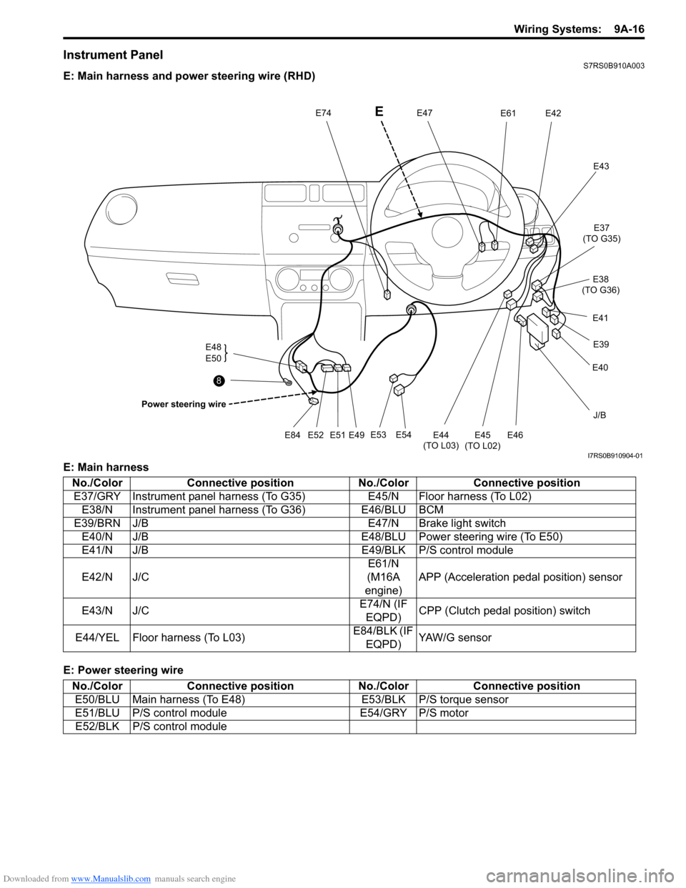
E: Main harness and power steering wire (RHD)
E: Main harness
E: Power steering wire
J/B
E54
E53
E49
E51E52E84
E48
E50
Power steering wire
E47E74E42E61
E43
E45
(TO L02)
E44
(TO L03)E46
E40 E39
E41 E37
(TO G35)
E38
(TO G36)
8
E
I7RS0B910904-01
No./Color Connective position No./ColorConnective position
E37/GRY Instrument panel harness (To G35) E45/N Floor harness (To L02)
E38/N Instrument panel harness (To G36) E46/BLU BCM
E39/BRN J/B E47/N Brake light switch
E40/N J/B E48/BLU Power steering wire (To E50)
E41/N J/B E49/BLK P/S control module
E42/N J/C E61/N
(M16A
engine) APP (Acceleration pedal position) sensor
E43/N J/C E74/N (IF
EQPD) CPP (Clutch pedal position) switch
E44/YEL Floor harness (To L03) E84/BLK (IF
EQPD) YAW/G sensor
No./Color Connective position No./ColorConnective position
E50/BLU Main harness (To E48) E53/BLK P/S torque sensor
E51/BLU P/S control module E54/GRY P/S motor
E52/BLK P/S control module
Page 1188 of 1496

Downloaded from www.Manualslib.com manuals search engine 9A-17 Wiring Systems:
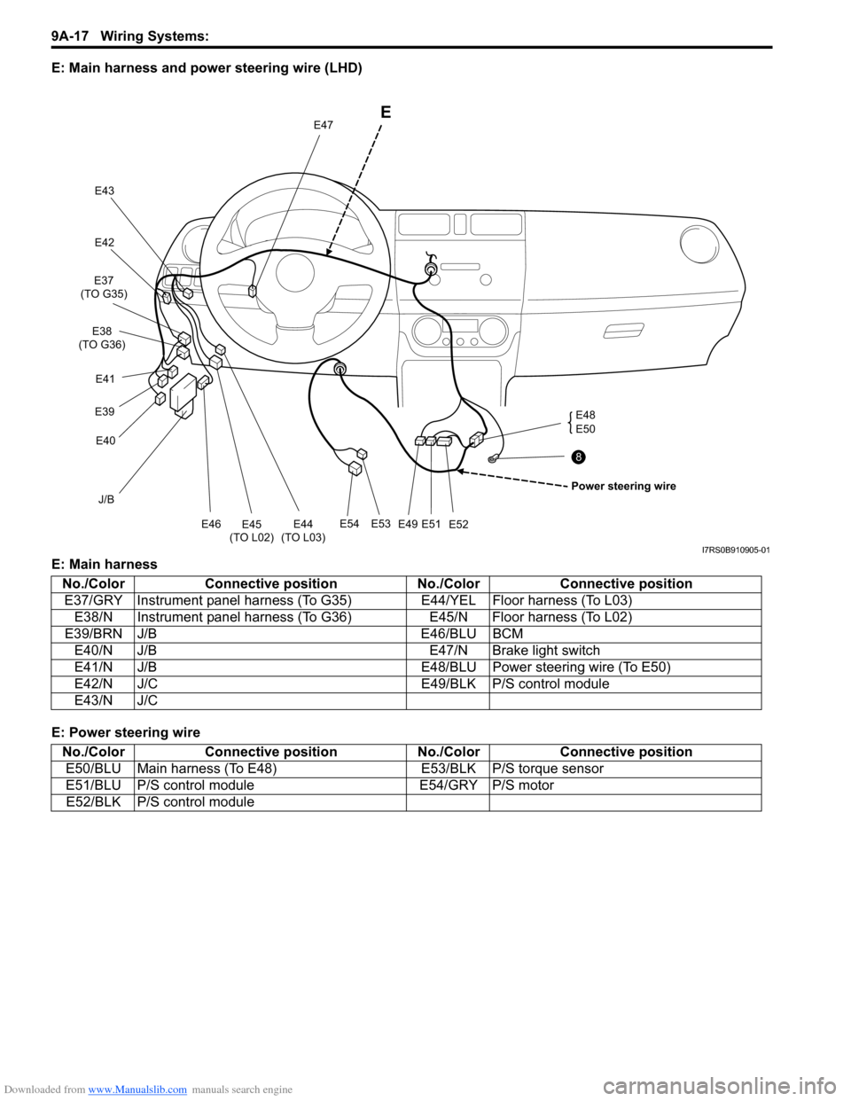
E: Main harness and power steering wire (LHD)
E: Main harness
E: Power steering wire
J/B
E54E53
E49E51E52 E48
E50
E
Power steering wire
E47
E43
E42
E45
(TO L02) E44
(TO L03)E46
E40
E39 E41
E37
(TO G35)
E38
(TO G36)
8
I7RS0B910905-01
No./Color Connective position No./ColorConnective position
E37/GRY Instrument panel harness (T o G35)E44/YEL Floor harness (To L03)
E38/N Instrument panel harness (To G36) E45/N Floor harness (To L02)
E39/BRN J/B E46/BLU BCM
E40/N J/B E47/N Brake light switch
E41/N J/B E48/BLU Power steering wire (To E50)
E42/N J/C E49/BLK P/S control module
E43/N J/C
No./Color Connective position No./ColorConnective position
E50/BLU Main harness (To E48) E53/BLK P/S torque sensor
E51/BLU P/S control module E54/GRY P/S motor
E52/BLK P/S control module
Page 1270 of 1496

Downloaded from www.Manualslib.com manuals search engine 9A-99 Wiring Systems:
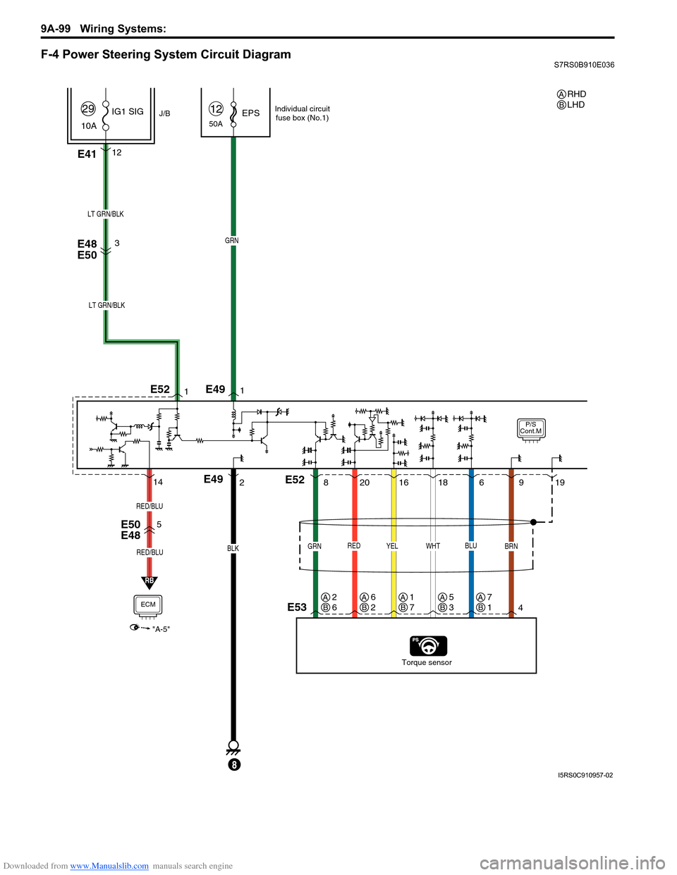
F-4 Power Steering System Circuit DiagramS7RS0B910E036
P/S
Cont.M
50AEPS12
E4112
J/B
10A IG1 SIG
29
RED
20
E48
E50
E50
E48
Torque sensor
BLK
E49
8
GRN
LT GRN/BLK
YEL
16
GRN
8
BRN
49
WHT
18
BLU
619
1
21
LT GRN/BLK
3
E53
E49
E52
E52
RB
5
ECM
"A-5"
RED/BLU
RED/BLU
14
Individual circuit
fuse box (No.1)
RHD
LHDAB
AB2
6AB6
2AB1
7AB5
3AB7
1
I5RS0C910957-02