2006 SUZUKI SWIFT AC Button
[x] Cancel search: AC ButtonPage 9 of 1496
Downloaded from www.Manualslib.com manuals search engine Precautions: 00-4
General PrecautionsS7RS0B0000002
The WARNING and CAUTION describe some general
precautions that you should observe when servicing a
vehicle. These general precautions apply to many of the
service procedures, and they will not necessarily be
repeated with each procedure to which they apply.
WARNING!
• Whenever raising a vehicle for service, be sure to follow the instructions under
“Vehicle Lifting Points in Section 0A”.
• When it is necessary to do service work with the engine running, make sure that
the parking brake is set fully and the
transmission is in Neutral (for manual
transmission vehicles) or Park (for
automatic transmission vehicles), Keep
hands, hair, clothing, tools, etc. away from
the fan and belts when the engine is
running.
• When it is necessary to run the engine indoors, make sure that the exhaust gas is
forced outdoors.
• Do not perform service work in areas where combustible materials can come in
contact with a hot exhaust system. When
working with toxic or flammable materials
(such as gasoline and refrigerant), make
sure that the area you work in is well-
ventilated.
• To avoid getting burned, keep away from hot metal parts such as the radiator,
exhaust manifold, tail pipe, muffler, etc.
• New and used engine oil can be hazardous. Children and pets may be
harmed by swallowing new or used oil.
Keep new and used oil and used engine oil
filters away from children and pets.
Continuous contact with used engine oil
has been found to cause [skin] cancer in
laboratory animals. Brief contact with used
oil may irritate skin. To minimize your
exposure to used engine oil, wear a long-
sleeve shirt and moisture-proof gloves
(such as dish washing gloves) when
changing engine oil. If engine oil contacts
your skin, wash thoroughly with soap and
water. Launder any clothing or rags if wet
with oil, recycle or properly dispose of
used oil and filters. • Be sure to observe following instructions
when handling service materials such as
fuel, oil, fluid, coolant, grease, sealant,
thread lock cement, etc. Otherwise, your
health may be ruined.
– Whenever handling any of these service materials, wear safety glasses to protect
your eyes. If it gets into your eye, it may
cause inflammation.
– Whenever handling any of these service materials, wear moistu re-proof gloves to
protect your skin. If it adheres to your
skin, it may cause inflammation.
– Do not swallow any of these service materials. It would cause diarrhea or
nausea.
– Keep all these materials out of children’s reach.
• Make sure the bonnet is fully closed and latched before driving. If it is not, it can fly
up unexpectedly during driving,
obstructing your view and resulting in an
accident.
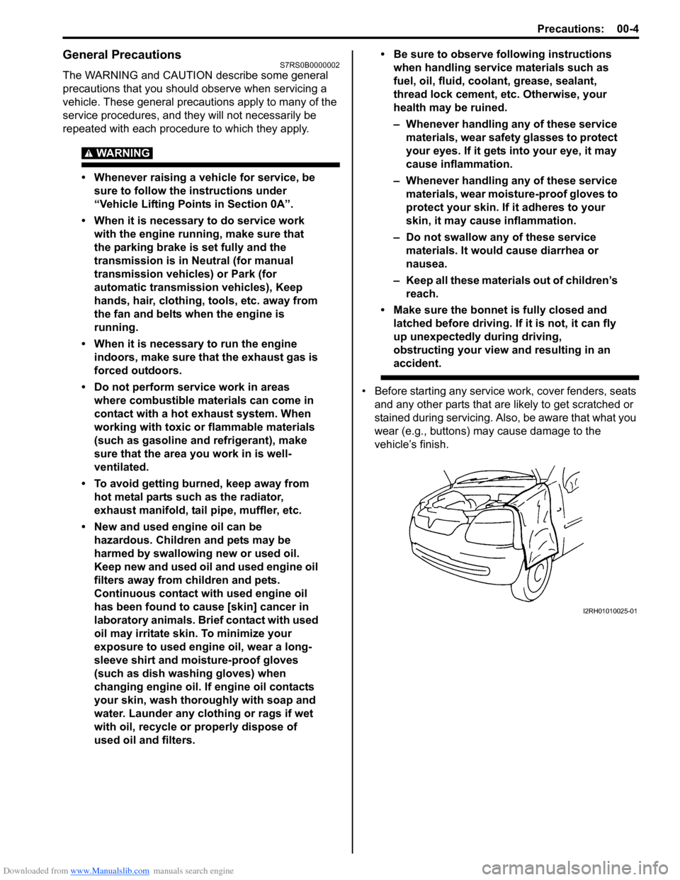
• Before starting any service work, cover fenders, seats and any other parts that are likely to get scratched or
stained during servicing. Also, be aware that what you
wear (e.g., buttons) ma y cause damage to the
vehicle’s finish.
I2RH01010025-01
Page 537 of 1496
Downloaded from www.Manualslib.com manuals search engine Parking Brake: 4D-2
Repair Instructions
Parking Brake Inspection and AdjustmentS7RS0B4406001
Inspection
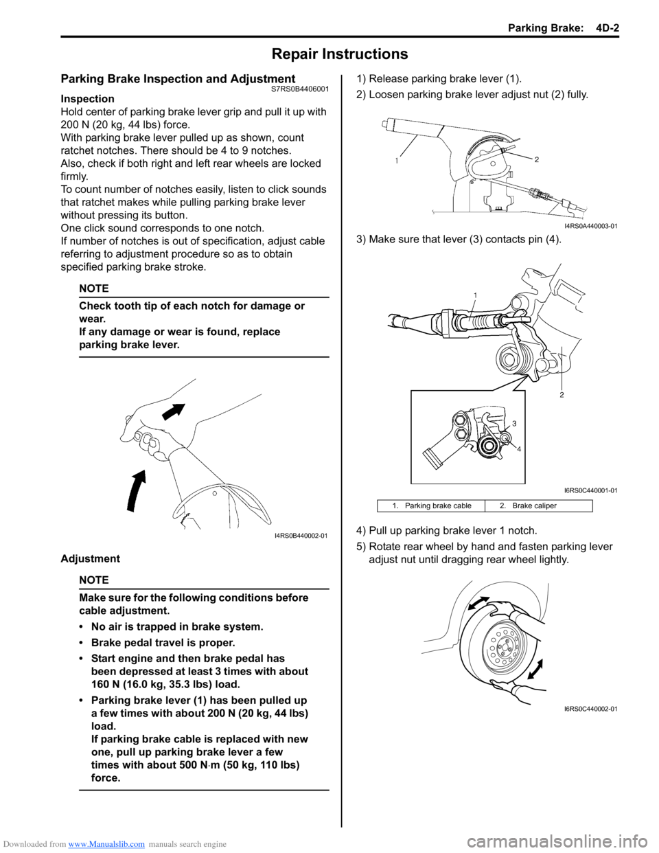
Hold center of parking brake lever grip and pull it up with
200 N (20 kg, 44 lbs) force.
With parking brake lever pulled up as shown, count
ratchet notches. There should be 4 to 9 notches.
Also, check if both right and left rear wheels are locked
firmly.
To count number of notches easily, listen to click sounds
that ratchet makes while pulling parking brake lever
without pressing its button.
One click sound corresponds to one notch.
If number of notches is out of specification, adjust cable
referring to adjustment procedure so as to obtain
specified parking brake stroke.
NOTE
Check tooth tip of each notch for damage or
wear.
If any damage or wear is found, replace
parking brake lever.
Adjustment
NOTE
Make sure for the following conditions before
cable adjustment.
• No air is trapped in brake system.
• Brake pedal travel is proper.
• Start engine and then brake pedal has been depressed at least 3 times with about
160 N (16.0 kg, 35.3 lbs) load.
• Parking brake lever (1) has been pulled up a few times with about 200 N (20 kg, 44 lbs)
load.
If parking brake cable is replaced with new
one, pull up parking brake lever a few
times with about 500 N ⋅m (50 kg, 110 lbs)
force.
1) Release parking brake lever (1).
2) Loosen parking brake lever adjust nut (2) fully.
3) Make sure that lever (3) contacts pin (4).
4) Pull up parking brake lever 1 notch.
5) Rotate rear wheel by hand and fasten parking lever adjust nut until dragging rear wheel lightly.
I4RS0B440002-01
1. Parking brake cable 2. Brake caliper
I4RS0A440003-01
I6RS0C440001-01
I6RS0C440002-01
Page 652 of 1496
Downloaded from www.Manualslib.com manuals search engine 5A-8 Automatic Transmission/Transaxle:
Brake Interlock System ConstructionS7RS0B5101004
Shift Lock Solenoid Control
This system consists of shift lock solenoid control
system and interlock cable control system.
The shift lock solenoid cont rol system is so designed
that the select lever can not be shifted from “P” range
position unless ignition switch is turned to “ON” or “ACC”
position and the brake pedal is depressed.
And interlock cable control system is so designed that
select lever cannot be shifted from “P” range position
unless ignition switch is turned to “ACC” or “ON”
position. Also, ignition key cannot be pulled out of key
slot unless select le ver is in “P” range.
Shift Lock Solenoid Manual Release
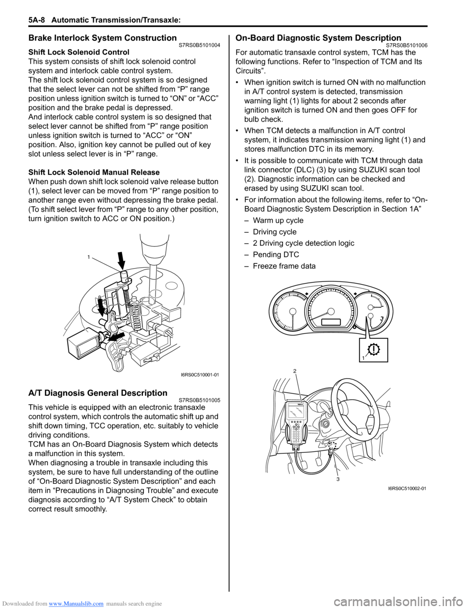
When push down shift lock solenoid valve release button
(1), select lever can be moved from “P” range position to
another range even without depressing the brake pedal.
(To shift select lever from “P” range to any other position,
turn ignition switch to ACC or ON position.)
A/T Diagnosis General DescriptionS7RS0B5101005
This vehicle is equipped with an electronic transaxle
control system, which controls the automatic shift up and
shift down timing, TCC operation, etc. suitably to vehicle
driving conditions.
TCM has an On-Board Diagnosis System which detects
a malfunction in this system.
When diagnosing a trouble in transaxle including this
system, be sure to have full understanding of the outline
of “On-Board Diagnostic System Description” and each
item in “Precautions in Diagnosing Trouble” and execute
diagnosis according to “A/T System Check” to obtain
correct result smoothly.
On-Board Diagnostic System DescriptionS7RS0B5101006
For automatic transaxle co ntrol system, TCM has the
following functions. Refer to “Inspection of TCM and Its
Circuits”.
• When ignition switch is turned ON with no malfunction in A/T control system is detected, transmission
warning light (1) lights for about 2 seconds after
ignition switch is turned ON and then goes OFF for
bulb check.
• When TCM detects a malfunction in A/T control system, it indicates transmission warning light (1) and
stores malfunction DTC in its memory.
• It is possible to communicate with TCM through data link connector (DLC) (3) by using SUZUKI scan tool
(2). Diagnostic information can be checked and
erased by using SUZUKI scan tool.
• For information about the following items, refer to “On- Board Diagnostic System De scription in Section 1A”
– Warm up cycle
– Driving cycle
– 2 Driving cycle detection logic
– Pending DTC
– Freeze frame data
1
I6RS0C510001-01
3
2
1
I6RS0C510002-01
Page 731 of 1496
Downloaded from www.Manualslib.com manuals search engine Automatic Transmission/Transaxle: 5A-87
Troubleshooting
Brake Interlock System InspectionS7RS0B5104047
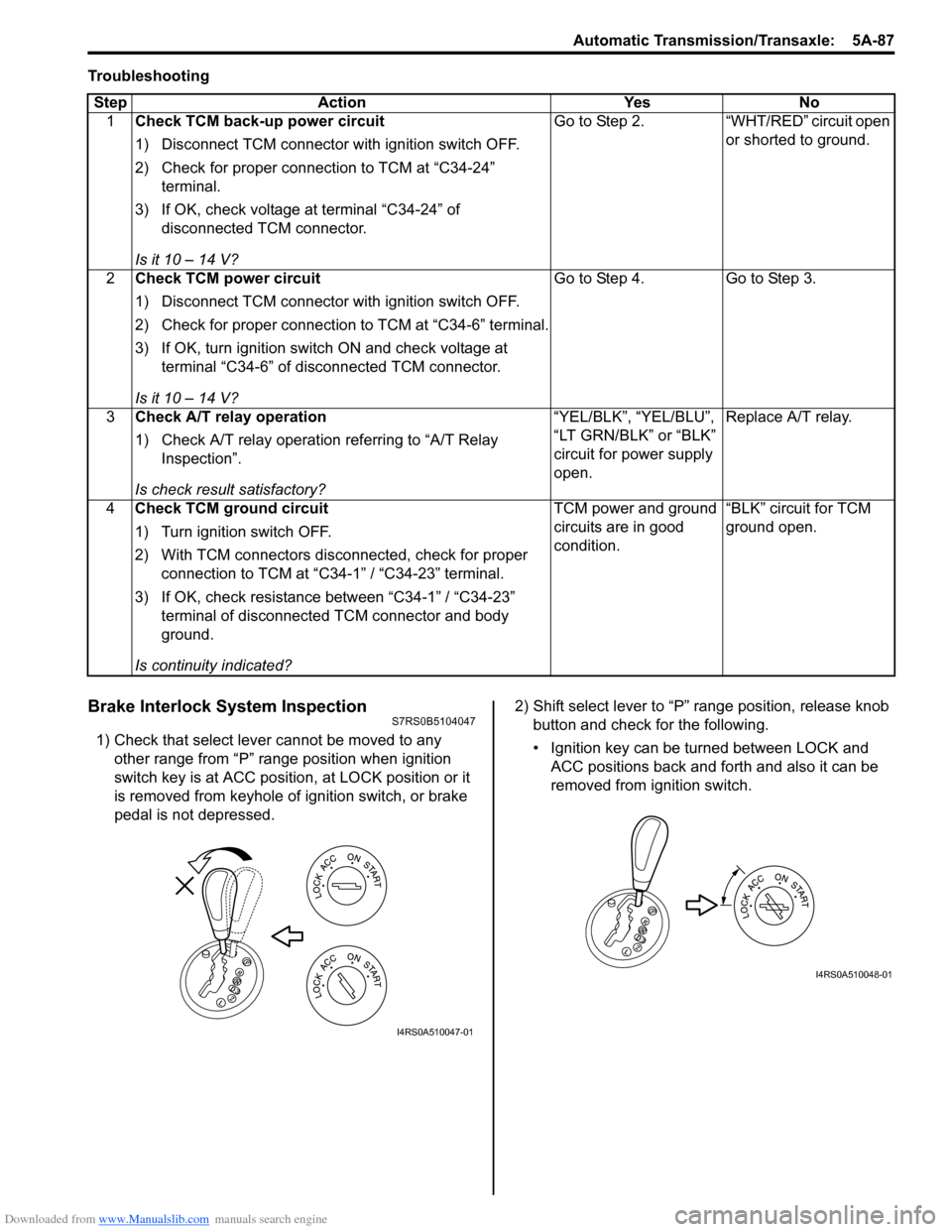
1) Check that select lever cannot be moved to any other range from “P” range position when ignition
switch key is at ACC position, at LOCK position or it
is removed from keyhole of ignition switch, or brake
pedal is not depressed. 2) Shift select lever to “P” range position, release knob
button and check for the following.
• Ignition key can be turned between LOCK and ACC positions back and forth and also it can be
removed from ignition switch.
Step Action Yes No
1 Check TCM back-up power circuit
1) Disconnect TCM connector with ignition switch OFF.
2) Check for proper connection to TCM at “C34-24”
terminal.
3) If OK, check voltage at terminal “C34-24” of disconnected TCM connector.
Is it 10 – 14 V? Go to Step 2. “WHT/RED” circuit open
or shorted to ground.
2 Check TCM power circuit
1) Disconnect TCM connector with ignition switch OFF.
2) Check for proper connection to TCM at “C34-6” terminal.
3) If OK, turn ignition switch ON and check voltage at
terminal “C34-6” of disconnected TCM connector.
Is it 10 – 14 V? Go to Step 4. Go to Step 3.
3 Check A/T relay operation
1) Check A/T relay operation referring to “A/T Relay
Inspection”.
Is check result satisfactory? “YEL/BLK”, “YEL/BLU”,
“LT GRN/BLK” or “BLK”
circuit for power supply
open.
Replace A/T relay.
4 Check TCM ground circuit
1) Turn ignition switch OFF.
2) With TCM connectors disconnected, check for proper
connection to TCM at “C34-1” / “C34-23” terminal.
3) If OK, check resistance between “C34-1” / “C34-23” terminal of disconnected TCM connector and body
ground.
Is continuity indicated? TCM power and ground
circuits are in good
condition.
“BLK” circuit for TCM
ground open.
I4RS0A510047-01
I4RS0A510048-01
Page 732 of 1496
Downloaded from www.Manualslib.com manuals search engine 5A-88 Automatic Transmission/Transaxle:
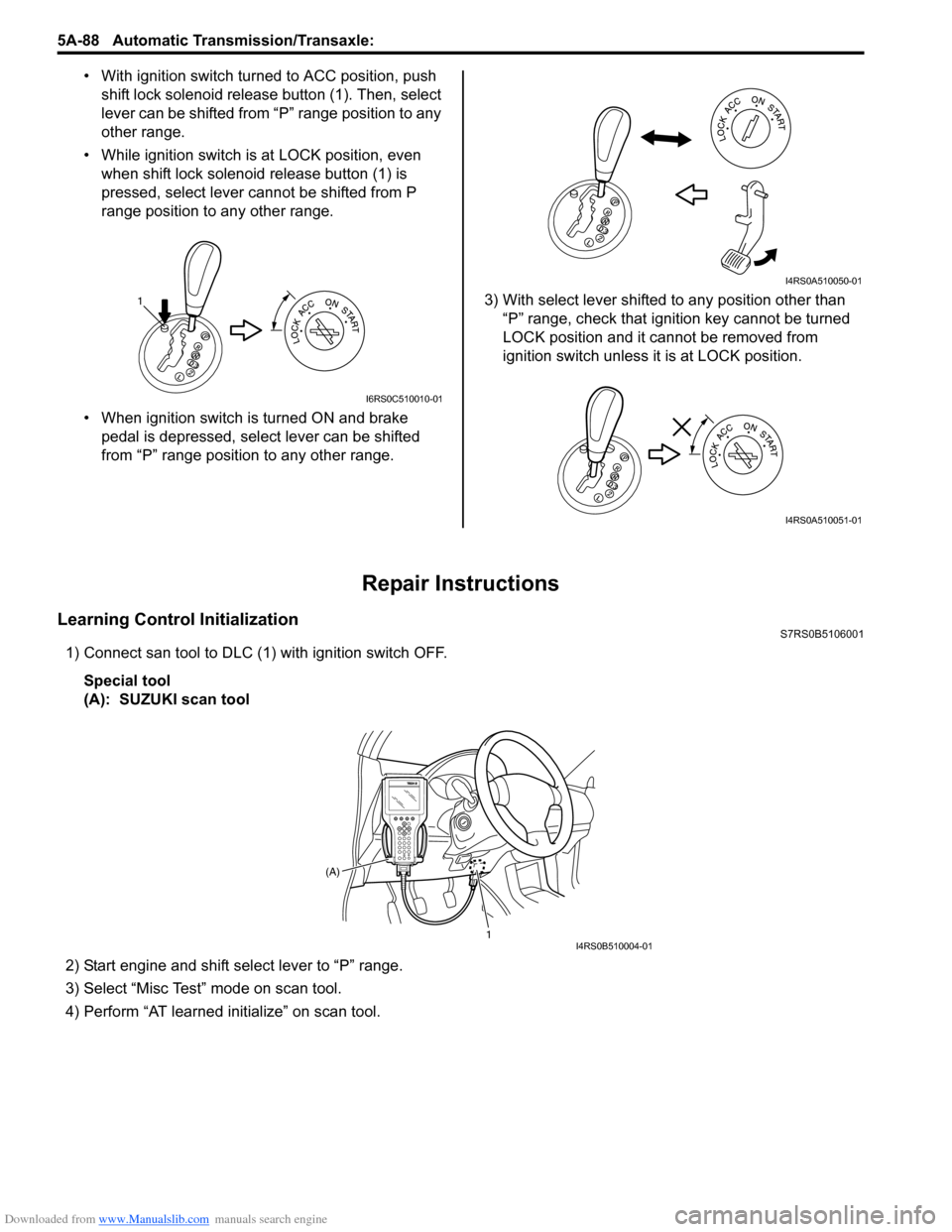
• With ignition switch turned to ACC position, push
shift lock solenoid release button (1). Then, select
lever can be shifted from “P” range position to any
other range.
• While ignition switch is at LOCK position, even when shift lock solenoid release button (1) is
pressed, select lever cannot be shifted from P
range position to any other range.
• When ignition switch is turned ON and brake pedal is depressed, select lever can be shifted
from “P” range position to any other range. 3) With select lever shifted to any position other than
“P” range, check that ignition key cannot be turned
LOCK position and it cannot be removed from
ignition switch unless it is at LOCK position.
Repair Instructions
Learning Control InitializationS7RS0B5106001
1) Connect san tool to DLC (1) with ignition switch OFF.
Special tool
(A): SUZUKI scan tool
2) Start engine and shift select lever to “P” range.
3) Select “Misc Test” mode on scan tool.
4) Perform “AT learned initialize” on scan tool.
1
I6RS0C510010-01
I4RS0A510050-01
I4RS0A510051-01
1
(A)I4RS0B510004-01
Page 738 of 1496
Downloaded from www.Manualslib.com manuals search engine 5A-94 Automatic Transmission/Transaxle:
5) Turn ignition switch to LOCK position.
6) Remove parking brake cover and console box.
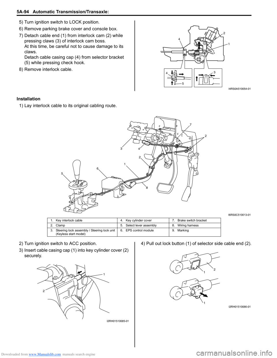
7) Detach cable end (1) from interlock cam (2) while
pressing claws (3) of interlock cam boss.
At this time, be careful no t to cause damage to its
claws.
Detach cable casing cap (4 ) from selector bracket
(5) while pressing check hook.
8) Remove interlock cable.
Installation 1) Lay interlock cable to its original cabling route.
2) Turn ignition switch to ACC position.
3) Insert cable casing cap (1) into key cylinder cover (2) securely. 4) Pull out lock button (1) of selector side cable end (2).
4
5 31
2
4
I4RS0A510054-01
1 2
3
4
5 6 7
8
2
I6RS0C510013-01
1. Key interlock cable 4. Key cylinder cover7. Brake switch bracket
2. Clamp 5. Select lever assembly 8. Wiring harness
3. Steering lock assembly / Steering lock unit (Keyless start model) 6. EPS control module
9. Marking
1
2
I2RH01510085-01
1
1
2
I2RH01510086-01
Page 739 of 1496
Downloaded from www.Manualslib.com manuals search engine Automatic Transmission/Transaxle: 5A-95
5) Shift select lever to “N” position.
NOTE
If select lever is in “P” position, shift select
lever referring to “Select Lever Inspection”.
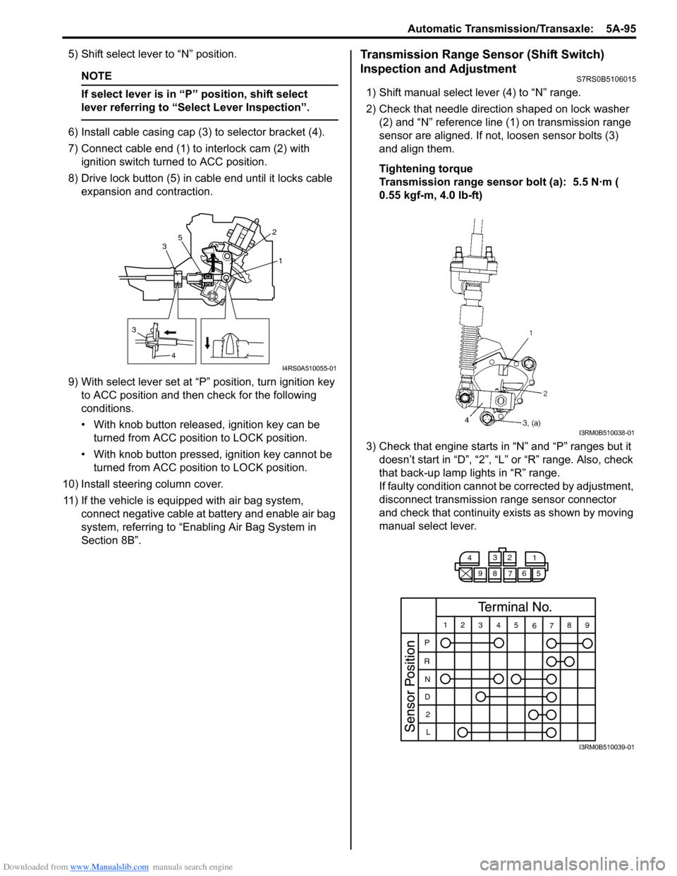
6) Install cable casing cap (3) to selector bracket (4).
7) Connect cable end (1) to interlock cam (2) with ignition switch turned to ACC position.
8) Drive lock button (5) in cable end until it locks cable expansion and contraction.
9) With select lever set at “P ” position, turn ignition key
to ACC position and then check for the following
conditions.
• With knob button released, ignition key can be turned from ACC position to LOCK position.
• With knob button pressed, ignition key cannot be
turned from ACC position to LOCK position.
10) Install steering column cover. 11) If the vehicle is equipped with air bag system, connect negative cable at battery and enable air bag
system, referring to “Enabling Air Bag System in
Section 8B”.
Transmission Range Sensor (Shift Switch)
Inspection and Adjustment
S7RS0B5106015
1) Shift manual select lever (4) to “N” range.
2) Check that needle direction shaped on lock washer (2) and “N” reference line (1) on transmission range
sensor are aligned. If not, loosen sensor bolts (3)
and align them.
Tightening torque
Transmission range sensor bolt (a): 5.5 N·m (
0.55 kgf-m, 4.0 lb-ft)
3) Check that engine starts in “N” and “P” ranges but it doesn’t start in “D”, “2”, “L” or “R” range. Also, check
that back-up lamp lights in “R” range.
If faulty condition cannot be corrected by adjustment,
disconnect transmission range sensor connector
and check that continuity ex ists as shown by moving
manual select lever.
3
4 1
2
3 5
I4RS0A510055-01
I3RM0B510038-01
4
3
2
1
98 76 5
12 345
6789
P
R N
D 2
L
I3RM0B510039-01
Page 1035 of 1496
Downloaded from www.Manualslib.com manuals search engine Seat Belts: 8A-4
Front Seat Belt Removal and InstallationS7RS0B8106002
WARNING!
• Never attempt to disassemble or repair the seat belt pretensioner (retractor
assembly). If any abnormality is found, be
sure to replace it with new one as an
assembly.
• Be sure to read “Precautions on Service and Diagnosis of Seat Belt” before starting
to work and observe every precaution
during work. Ne glecting them may result in
personal injury or una ctivation of the seat
belt pretensioner when necessary.
Removal
1) Disconnect negative (–) cable at battery.
2) Disable air bag system. Refer to “Disabling Air Bag System in Section 8B”.
3) Remove center pillar lower trim.
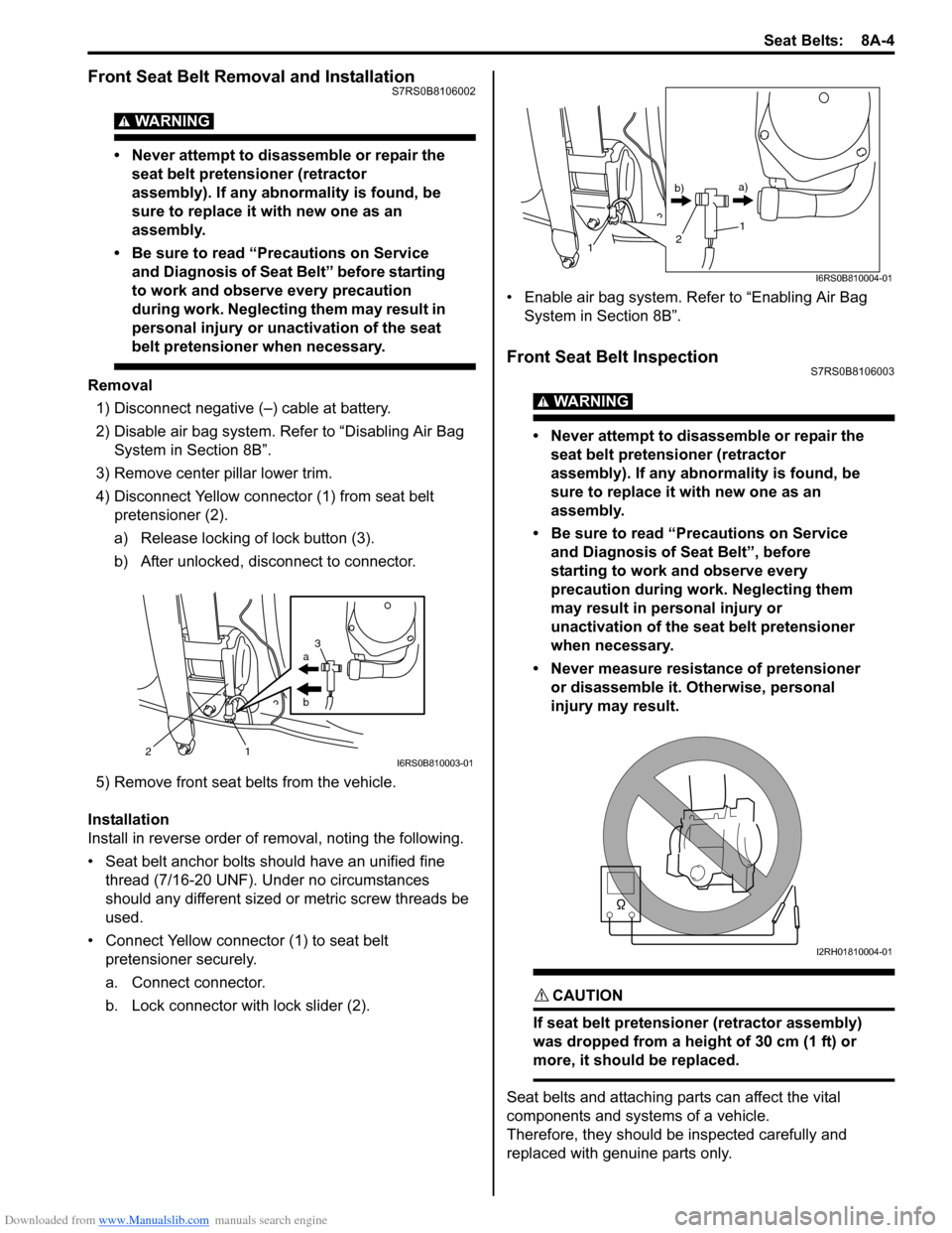
4) Disconnect Yellow connector (1) from seat belt pretensioner (2).
a) Release locking of lock button (3).
b) After unlocked, disconnect to connector.
5) Remove front seat belts from the vehicle.
Installation
Install in reverse order of removal, noting the following.
• Seat belt anchor bolts should have an unified fine thread (7/16-20 UNF). Under no circumstances
should any different sized or metric screw threads be
used.
• Connect Yellow connector (1) to seat belt pretensioner securely.
a. Connect connector.
b. Lock connector with lock slider (2). • Enable air bag system. Refer to “Enabling Air Bag
System in Section 8B”.
Front Seat Belt InspectionS7RS0B8106003
WARNING!
• Never attempt to disassemble or repair the seat belt pretensioner (retractor
assembly). If any abnormality is found, be
sure to replace it with new one as an
assembly.
• Be sure to read “Precautions on Service and Diagnosis of Seat Belt”, before
starting to work and observe every
precaution during work. Neglecting them
may result in personal injury or
unactivation of the seat belt pretensioner
when necessary.
• Never measure resistance of pretensioner or disassemble it. Otherwise, personal
injury may result.
CAUTION!
If seat belt pretensioner (retractor assembly)
was dropped from a height of 30 cm (1 ft) or
more, it should be replaced.
Seat belts and attaching parts can affect the vital
components and systems of a vehicle.
Therefore, they should be inspected carefully and
replaced with genuine parts only.
a
b
21 3I6RS0B810003-01
1
1
2
b)
a)
I6RS0B810004-01
I2RH01810004-01