2006 SUZUKI SWIFT Ground points
[x] Cancel search: Ground pointsPage 26 of 1496

Downloaded from www.Manualslib.com manuals search engine 0A-5 General Information:
Vehicle Lifting PointsS7RS0B0101005
WARNING!
• Before applying hoist to underbody, always take vehicle balance throughout service into
consideration. Vehicle balance on hoist may change depending on what part to be removed.
• Before lifting up the vehicle, check to be sure that end of hoist arm is not in contact with brake pipe,
fuel pipe, bracket or any other part.
• When using frame contact hoist, apply hoist as shown (right and left at the same position). Lift up
the vehicle till 4 tires are a little off the ground and make sure that the vehicle will not fall off by
trying to move vehicle body in both ways. Work can be started only after this confirmation.
• Make absolutely sure to lock hoist after vehicle is hoisted up.
When Using Frame Contact Hoist
1
:2
:3
4
4
I4RS0A010001-01
1. Vehicle front
3. Floor jack position
2. Support position for frame contact hoist and safety stand 4. Body mounting stay
Page 403 of 1496
Downloaded from www.Manualslib.com manuals search engine Starting System: 1I-2
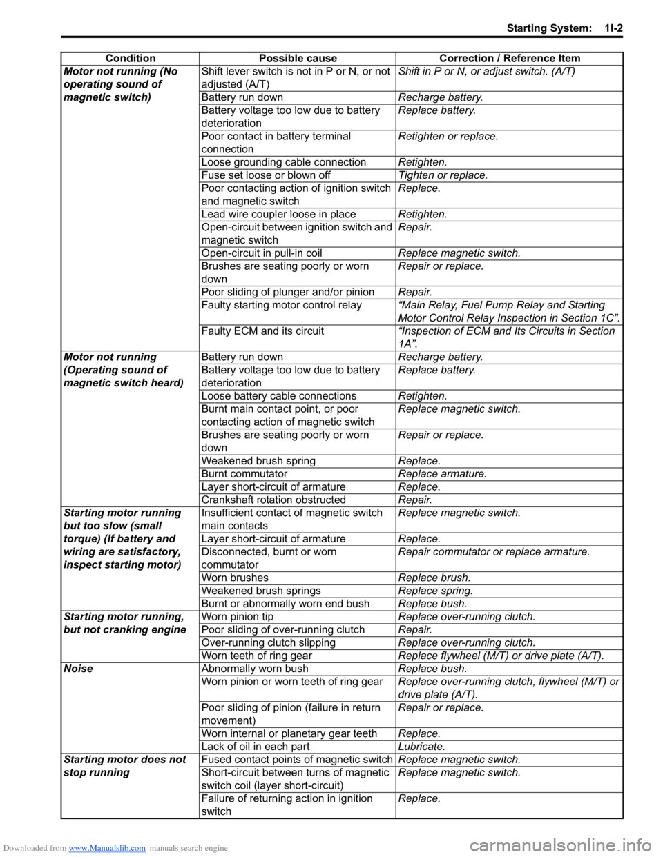
ConditionPossible cause Correction / Reference Item
Motor not running (No
operating sound of
magnetic switch) Shift lever switch is not in P or N, or not
adjusted (A/T)
Shift in P or N, or
adjust switch. (A/T)
Battery run down Recharge battery.
Battery voltage too low due to battery
deterioration Replace battery.
Poor contact in battery terminal
connection Retighten or replace.
Loose grounding cable connection Retighten.
Fuse set loose or blown off Tighten or replace.
Poor contacting action of ignition switch
and magnetic switch Replace.
Lead wire coupler loose in place Retighten.
Open-circuit between ignition switch and
magnetic switch Repair.
Open-circuit in pull-in coil Replace magnetic switch.
Brushes are seating poorly or worn
down Repair or replace.
Poor sliding of plunger and/or pinion Repair.
Faulty starting motor control relay “Main Relay, Fuel Pump Relay and Starting
Motor Control Relay Inspection in Section 1C”.
Faulty ECM and its circuit “Inspection of ECM and Its Circuits in Section
1A”.
Motor not running
(Operating sound of
magnetic switch heard) Battery run down
Recharge battery.
Battery voltage too low due to battery
deterioration Replace battery.
Loose battery cable connections Retighten.
Burnt main contact point, or poor
contacting action of magnetic switch Replace magnetic switch.
Brushes are seating poorly or worn
down Repair or replace.
Weakened brush spring Replace.
Burnt commutator Replace armature.
Layer short-circuit of armature Replace.
Crankshaft rotation obstructed Repair.
Starting motor running
but too slow (small
torque) (If battery and
wiring are satisfactory,
inspect starting motor) Insufficient contact
of magnetic switch
main contacts Replace magnetic switch.
Layer short-circuit of armature Replace.
Disconnected, burnt or worn
commutator Repair commutator or replace armature.
Worn brushes Replace brush.
Weakened brush springs Replace spring.
Burnt or abnormally worn end bush Replace bush.
Starting motor running,
but not cranking engine Worn pinion tip
Replace over-running clutch.
Poor sliding of over-running clutch Repair.
Over-running clutch slipping Replace over-running clutch.
Worn teeth of ring gear Replace flywheel (M/T) or drive plate (A/T).
Noise Abnormally worn bush Replace bush.
Worn pinion or worn teeth of ring gear Replace over-running clutch, flywheel (M/T) or
drive plate (A/T).
Poor sliding of pinion (failure in return
movement) Repair or replace.
Worn internal or planetary gear teeth Replace.
Lack of oil in each part Lubricate.
Starting motor does not
stop running Fused contact points of magnetic switch
Replace magnetic switch.
Short-circuit between turns of magnetic
switch coil (layer short-circuit) Replace magnetic switch.
Failure of returning action in ignition
switch Replace.
Page 558 of 1496
Downloaded from www.Manualslib.com manuals search engine 4E-19 ABS:
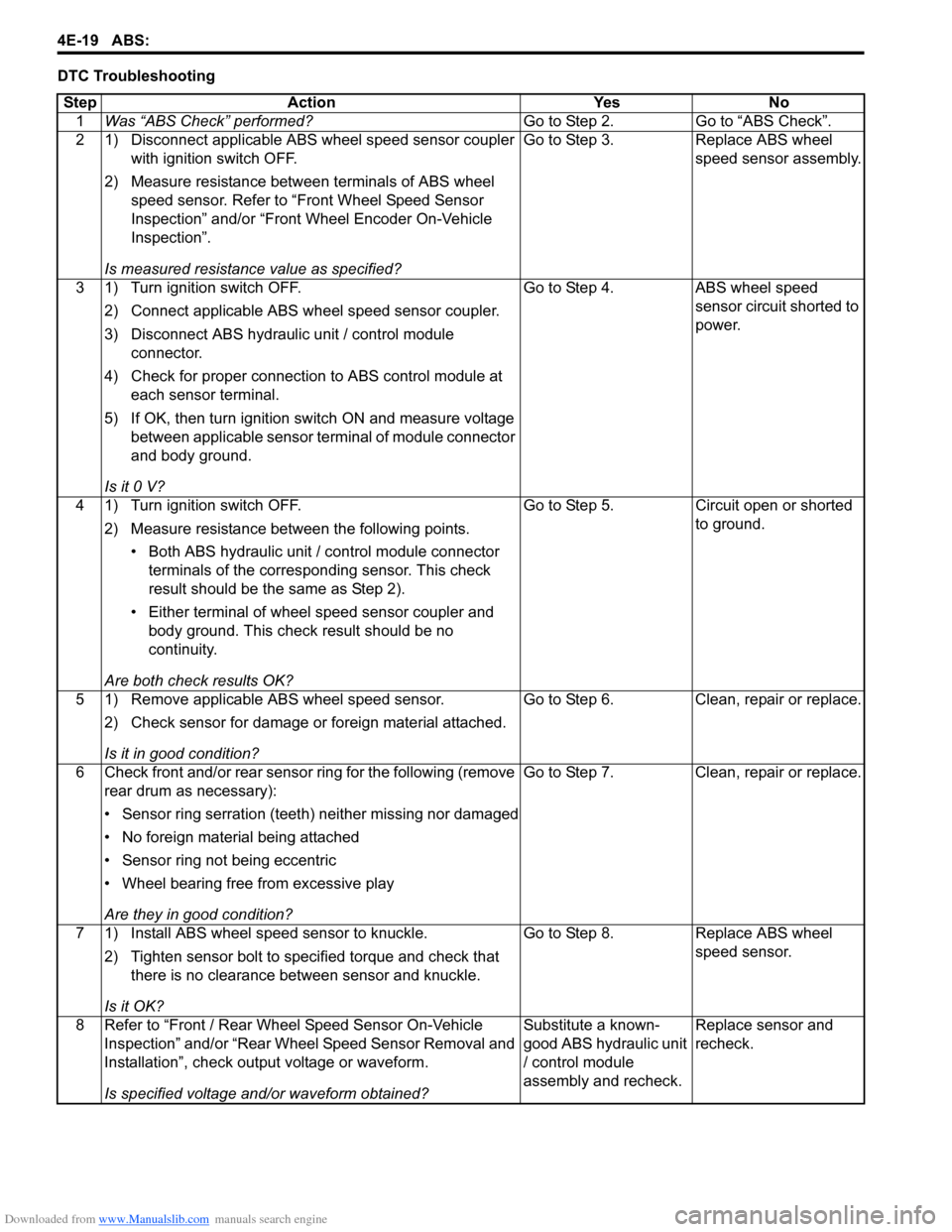
DTC TroubleshootingStep Action Yes No 1 Was “ABS Check” performed? Go to Step 2. Go to “ABS Check”.
2 1) Disconnect applicable ABS wheel speed sensor coupler with ignition switch OFF.
2) Measure resistance betw een terminals of ABS wheel
speed sensor. Refer to “Front Wheel Speed Sensor
Inspection” and/or “Front Wheel Encoder On-Vehicle
Inspection”.
Is measured resistance value as specified? Go to Step 3. Replace ABS wheel
speed sensor assembly.
3 1) Turn ignition switch OFF. 2) Connect applicable ABS wh eel speed sensor coupler.
3) Disconnect ABS hydraulic unit / control module connector.
4) Check for proper connection to ABS control module at each sensor terminal.
5) If OK, then turn ignition switch ON and measure voltage between applicable sensor terminal of module connector
and body ground.
Is it 0 V? Go to Step 4. ABS wheel speed
sensor circuit shorted to
power.
4 1) Turn ignition switch OFF. 2) Measure resistance between the following points.• Both ABS hydraulic unit / control module connector terminals of the correspo nding sensor. This check
result should be the same as Step 2).
• Either terminal of wheel speed sensor coupler and body ground. This check result should be no
continuity.
Are both check results OK? Go to Step 5. Circuit open or shorted
to ground.
5 1) Remove applicable ABS wheel speed sensor. 2) Check sensor for damage or foreign material attached.
Is it in good condition? Go to Step 6. Clean, repair or replace.
6 Check front and/or rear sensor ring for the following (remove rear drum as necessary):
• Sensor ring serration (teeth) neither missing nor damaged
• No foreign material being attached
• Sensor ring not being eccentric
• Wheel bearing free from excessive play
Are they in good condition? Go to Step 7. Clean, repair or replace.
7 1) Install ABS wheel speed sensor to knuckle. 2) Tighten sensor bolt to specified torque and check that there is no clearance between sensor and knuckle.
Is it OK? Go to Step 8. Replace ABS wheel
speed sensor.
8 Refer to “Front / Rear Wheel Speed Sensor On-Vehicle Inspection” and/or “Rear Wheel Speed Sensor Removal and
Installation”, check output voltage or waveform.
Is specified voltage and/or waveform obtained? Substitute a known-
good ABS hydraulic unit
/ control module
assembly and recheck.
Replace sensor and
recheck.
Page 611 of 1496
Downloaded from www.Manualslib.com manuals search engine Electronic Stability Program: 4F-37
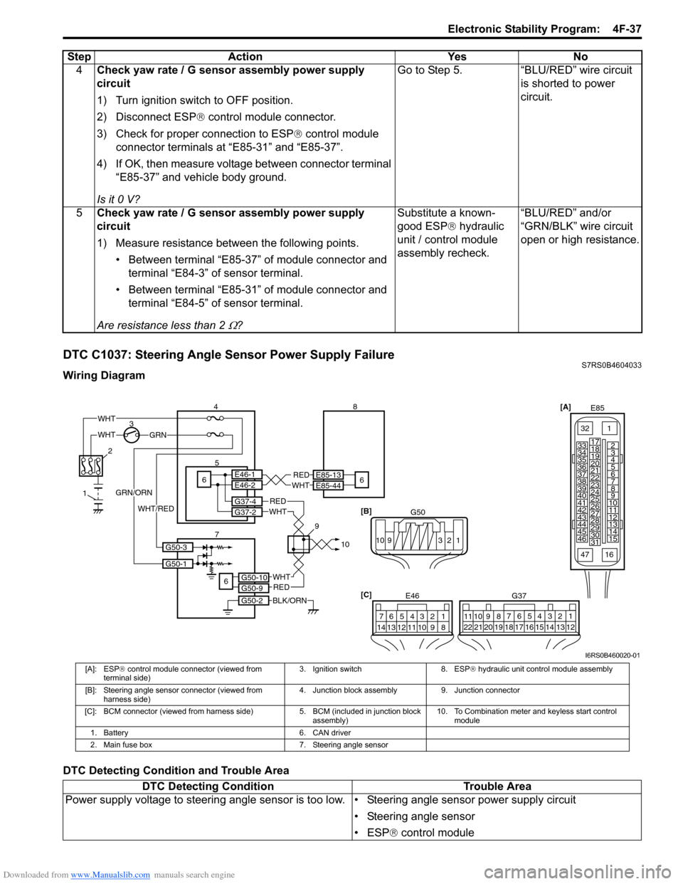
DTC C1037: Steering Angle Sensor Power Supply FailureS7RS0B4604033
Wiring Diagram
DTC Detecting Condition and Trouble Area4
Check yaw rate / G sensor assembly power supply
circuit
1) Turn ignition switch to OFF position.
2) Disconnect ESP ® control module connector.
3) Check for proper connection to ESP ® control module
connector terminals at “E85-31” and “E85-37”.
4) If OK, then measure voltage between connector terminal “E85-37” and vehicle body ground.
Is it 0 V? Go to Step 5. “BLU/RED” wire circuit
is shorted to power
circuit.
5 Check yaw rate / G sensor assembly power supply
circuit
1) Measure resistance between the following points.
• Between terminal “E85-37” of module connector and terminal “E84-3” of sensor terminal.
• Between terminal “E85-31” of module connector and terminal “E84-5” of sensor terminal.
Are resistance less than 2
Ω? Substitute a known-
good ESP
® hydraulic
unit / control module
assembly recheck. “BLU/RED” and/or
“GRN/BLK” wire circuit
open or high resistance.
Step
Action YesNo
[A]
E85
161
15
2
3
4
5
6
7
8
9
10
11
12
13
14
17
18
19
20
21
22
23
24
25
26
27
28
29
30
31
3233
34
35
36
37
38
39
40
41
42
43
44
45
46
47
[C] G37
E46
124
53
67
891011121314124
53
67
891011
1213141516171819202122
WHTGRN
3
E85-13
E85-44REDWHT65E46-1E46-2
4 8
6
BLK/ORN
REDWHT
REDWHT
G37-4G37-2
G50-10G50-9
G50-2
6
2
1
7 910
G50-1
G50-3
GRN/ORN
WHT/RED
WHT
[B]
G50
109 321
I6RS0B460020-01
[A]: ESP® control module connector (viewed from
terminal side) 3. Ignition switch 8. ESP
® hydraulic unit control module assembly
[B]: Steering angle sensor connector (viewed from harness side) 4. Junction block assembly 9. Junction connector
[C]: BCM connector (viewed from harnes s side) 5. BCM (included in junction block
assembly) 10. To Combination meter and keyless start control
module
1. Battery 6. CAN driver
2. Main fuse box 7. Steering angle sensor
DTC Detecting Condition Trouble Area
Power supply voltage to steering angle sensor is to o low. • Steering angle sensor power supply circuit
• Steering angle sensor
• ESP® control module
Page 1178 of 1496
Downloaded from www.Manualslib.com manuals search engine 9A-7 Wiring Systems:
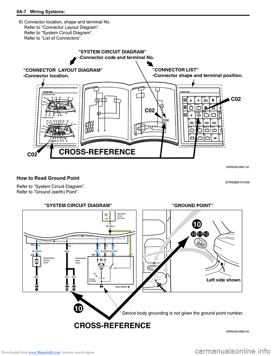
6) Connector location, shape and terminal No.Refer to “Connector Layout Diagram”.
Refer to “System Circuit Diagram”.
Refer to “List of Connectors”.
How to Read Ground PointS7RS0B9101006
Refer to “System Circuit Diagram”.
Refer to “Ground (earth) Point”.
"SYSTEM CIRCUIT DIAGRAM"
-Connector code and terminal No.
"CONNECTOR LAYOUT DIAGRAM"
-Connector location.
CROSS-REFERENCE
"CONNECTOR LIST"
-Connector shape and terminal position.
C02
C02 C02
C02
C02
C02
I5RW0A910991-02
Left side shown
101112
"SYSTEM CIRCUIT DIAGRAM"
"GROUND POINT"
CROSS-REFERENCE
Windoshield
washer
motor Individual
circuit
fuse box
2015A
Windoshield
wiper
motor
E40
E09
E20
16
2
1
Off
On
Circuit
breaker
60A-B003-
YEL/BLU
1
205
2
134
67
BLU/BLK
BLK
10
BLK
BLK
9
10
10
BLK
M
BLUBLU/WHTBLU/RED
M
Device body grounding is not given the ground point number.
I5RW0A910992-02
Page 1201 of 1496
Downloaded from www.Manualslib.com manuals search engine Wiring Systems: 9A-30
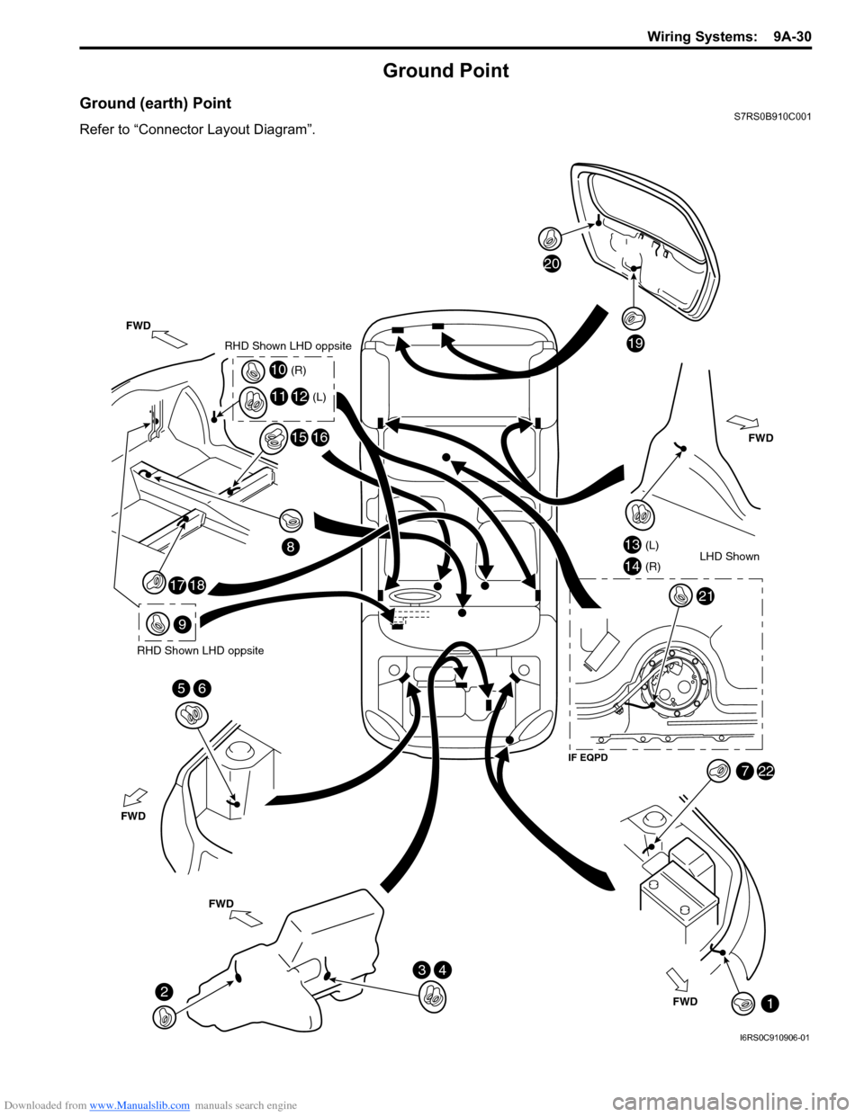
Ground Point
Ground (earth) PointS7RS0B910C001
Refer to “Connector Layout Diagram”.
21
20
19
13LHD Shown
RHD Shown LHD oppsite
RHD Shown LHD oppsite (L)14(R)
722
34
12FWD
56
17
8
9
10
FWD
FWD
(R)
1112(L)
1516FWD
18
FWD
IF EQPD
I6RS0C910906-01